A tissue covered 3D printed structure?

quorneng

Master member
The conventional approach to a lightweight plane wing is to use 'stick and tissue'.
Such a structure can be equalled using foam, particularly with thin sheet Depron, and it can be more robust too.
More out of curiosity than any likely benefit I wondered what could be done if the structure was not made of sticks of wood but from 3D printed parts.
I have already used printed ribs quite successfully with almost no weight penalty compared to even a foam rib.
This rib for an 8" (200 mm) chord wing printed in PLA weighs 1.2 g
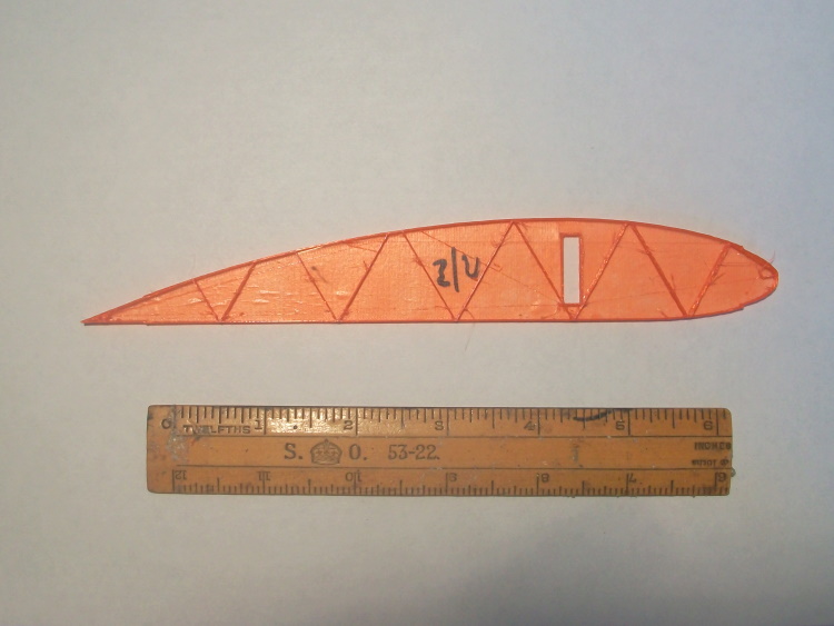
PrintRib.JPG

The big question is would a spar printed in PLA be strong enough and how could a 1 m spar be printed with a bed limitation of 220 mm?
The first issue was to recognise that a printed structure is much stronger along the line of the filament than across it so it would be important that the print ran along the line of the spar.
All printer filament is heavy compared to balsa a hollow 'box' spar would provide strength and rigidity for minimum weight.
A 200 mm 'test' spar section carrying an 18 oz (500 g) centre load load with no visible distortion.
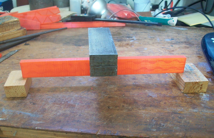
OutSprTest.JPG

The spar itself weighs only 7.8 g
So far so good but how would it behave if 5 of these were joined end to end to create a 1000 mm spar?
Hmmmm!
 

dap35

Elite member
The conventional approach to a lightweight plane wing is to use 'stick and tissue'.
Such a structure can be equalled using foam, particularly with thin sheet Depron, and it can be more robust too.
More out of curiosity than any likely benefit I wondered what could be done if the structure was not made of sticks of wood but from 3D printed parts.
I have already used printed ribs quite successfully with almost no weight penalty compared to even a foam rib.
This rib for an 8" (200 mm) chord wing printed in PLA weighs 1.2 g
View attachment 174114
The big question is would a spar printed in PLA be strong enough and how could a 1 m spar be printed with a bed limitation of 220 mm?
The first issue was to recognise that a printed structure is much stronger along the line of the filament than across it so it would be important that the print ran along the line of the spar.
All printer filament is heavy compared to balsa a hollow 'box' spar would provide strength and rigidity for minimum weight.
A 200 mm 'test' spar section carrying an 18 oz (500 g) centre load load with no visible distortion.
View attachment 174115
The spar itself weighs only 7.8 g
So far so good but how would it behave if 5 of these were joined end to end to create a 1000 mm spar?
Hmmmm!
You would need overlap at each joint to transfer the load, most of which would be in the upper and lower cap. You might consider graphite arrows. They are only $5 each at Walmart and very light. It would only take one joint to get 1M.
 

varg

Build cheap, crash cheap
Joining the spar sections successfully would be the difficulty. I suggest a double butt lap joint or double strap butt joint between spar cap sections if you choose to go this route. The issue is that when overlapping, the weakness of 3D printing; layer adhesion, would make it significantly weaker than a single piece. You'll want to bind your joined area in something like a wrap of fiberglass in order to assist layer adhesion at the joint.

PLA in general for rc aircraft construction... Due to the process itself, it's hard to define the mechanical properties of a FDM printed material in a specific sense and compare it to balsa. The properties of the parts printed are highly variable depending on print temperature, filament quality and moisture content, and print settings. So comparing it generally with these sources:
Tropical Balsa Wood properties
PLA properties
PLA datasheet
Balsa properties

We can see from the flexural modulus that PLA and balsa are also fairly similar in stiffness and that both are highly anisotropic materials, we want to load both 'with the grain' for good performance. The similarity ends there. We know that the density of PLA is around 1.24g/cm^3 and the density of balsa, variable by grade, is around 0.16g/cm^3. Balsa has a significantly higher axial tensile ultimate strength, at 73MPa, than PLA's ~50MPa, though PLA has a higher perpendicular ultimate tensile strength ~39MPa than Balsa at 1MPa. We would never willingly place a tensile or bending load in the perpendicular direction with either material though. In tensile loading if we compare a part of identical dimensions we wind up with something that is 7.75x heavier but only 68% as strong, this is not good. In compression we see that PLA is significantly stronger (around 10.4x higher) especially when we consider that softer balsa is typically used in model aircraft construction. If we load the PLA part in compression we can theoretically achieve the same strength as a balsa part with less weight, or we can achieve a stronger part with the same weight, but the issue is finding a place where pure compression loading will be experienced in an aircraft. Spar caps are exposed to compression or tension depending on which cap and the direction of loading, so a PLA spar cap might work well, but the issue of continuous material becomes apparent there since you're not likely to be able to print a continuous spar cap.

Realistically, as much of a fan of 3D printing as I am, I must admit that it is overall of limited usefulness for making RC airplanes and should be consigned to small parts. Wing ribs make sense.
 

quorneng

Master member
varg
Whist I agree with your observations about ultimate strength values we have to recognise that most models are not particularly structurally efficient being a compromise for ease or practicality of assembly. With 3D printing you can in theory make every thing exactly to the required dimension assuming of course that you know what that dimension needs to be.
My initial thoughts are to arrange that each spar section 'plugs into' its neighbour with a close fit and sufficient overlap to ensure the tensile and compression forces are transferred. The fact that each section of the spar would get progressively smaller would reasonably match the bending forces generated in a cantilever wing.
As a proof of concept I created 3 short plug in spar sections each with a typical rib.
Spar1.JPG

I judged a 20 mm overlap, with glue, would give a sufficient load transfer.
Spar2.JPG

The top and bottom flanges of the box spars are thinner in each successive section.
To achieve a 1000 mm span would require a 240 mm centre section, then a 220 mm mid and a 200 mm outer. Such a layout would have the advantage that there would be no joint at the wing centre, the point of maximum bending.
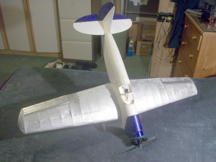
To give a reasonable chance of success the tissue covered printed wing is intended to be used as a replacement on this particularly light weight but powerful Depron 1000 mm low wing plane.
19Jun18.JPG

Note it already sports a 'printed' 9 cylinder radial . ;)
 

"Corpse"

Legendary member
varg
Whist I agree with your observations about ultimate strength values we have to recognise that most models are not particularly structurally efficient being a compromise for ease or practicality of assembly. With 3D printing you can in theory make every thing exactly to the required dimension assuming of course that you know what that dimension needs to be.
My initial thoughts are to arrange that each spar section 'plugs into' its neighbour with a close fit and sufficient overlap to ensure the tensile and compression forces are transferred. The fact that each section of the spar would get progressively smaller would reasonably match the bending forces generated in a cantilever wing.
As a proof of concept I created 3 short plug in spar sections each with a typical rib.
View attachment 174195
I judged a 20 mm overlap, with glue, would give a sufficient load transfer.
View attachment 174196
The top and bottom flanges of the box spars are thinner in each successive section.
To achieve a 1000 mm span would require a 240 mm centre section, then a 220 mm mid and a 200 mm outer. Such a layout would have the advantage that there would be no joint at the wing centre, the point of maximum bending.
To give a reasonable chance of success the tissue covered printed wing is intended to be used as a replacement on this particularly light weight but powerful Depron 1000 mm low wing plane.
View attachment 174197
Note it already sports a 'printed' 9 cylinder radial . ;)
I love a wee bit of science! I've never thought of this before. It being PLA means that it'll have that 'bounce" and It won't crack like balsa. Great idea!
 

Boberticus

Active member
some interesting numbers ive found looking into the same thing,

specific density of medium balsawood is .13grams per sq cm.
specific density of PLA is 1.2 grams a sq cm

so if i pull up a set of plain old balsa plans and find a offset that was made out of balsa, i could make the exact same thing but out of plastic and just have to have it be a 1/10th of the area, cause its a bit less than ten times heaver, and it should be literally the same thing, weight wise.

here's a sketch of a part for a Northrum N1m i'm working on. im planning on using a 30in carbon fiber arrow like how dap35 said,too.

right now im sitting at 15% area compared to the same thing the plans call for in 3/16th balsa. cool part is i dont have to print it at 3/16' thick, im going to print a bunch at thinner and thinner thicknesses till i get the lightest stiff part i can get. the thin flange for the DTFB leading and film trailing edges can be as wide as i want them to be too, not limited to 3/16" here either.

Purple bit is going to be a c spar like what quorneng is doing, with tabs that i havent drawn in yet that'll slot into each rib for glueing. planning on using pla and acetone so the plastic melts and fuses together, but want the stiffnes of a carbon fiber arrow too.
 

Attachments

  • N1-M____W7.pdf
    2.6 KB · Views: 0

varg

Build cheap, crash cheap
What's the geometry of your spar joiners, @quorneng , to avoid the tendency of the bending moment to split the joined spar sections or their joiners? I don't see the practicality in printing the spar other than as an experiment with a plane that is replaceable. For me, it's easy to find a suitable piece of wood or carbon fiber, fiberglass, or even aluminum channel, and leave the printing for formers, ribs, scale details like your nice radial, etc. I'd like to see it work for sure, I just am skeptical of using printed parts for anything structural in models, though I have used printed stiffeners for my profile 3D plane and a slow flier with a cambered foamboard wing.

@Boberticus That sounds like what I've considered doing for more complex builds, just haven't had the time to print and build what I've drawn up. Not that I haven't been printing, my most recent 3D printed projects have been flight simulator rudder pedals and a replica of a strange clutchless limited slip differential used in the kubelwagen in WW2. What are you planning to do with the acetone? It was my understanding that chemically, PLA should not react much with acetone, if at all, and any reaction a PLA part had to it was due to additives or adulterants in the PLA.
 

quorneng

Master member
varg
If the join is a close fit and glued together the compression and tensile forces will be simply transferred from one spar flange to the other. The same will apply to the shear forces in the webs between them. There will be no tendency to split the box as there would be in a dry joint.
With a box spar that has thin walls there is of course a requirement to provide internal support to ensure the shape is maintained under load. The slicer program has a wide range of 'fills' available to achieve this.
So far I have printed this 5 section 1000 mm spar.
FullSpar1.JPG

The middle section incorporates 3 degrees dihedral. It represents about 10 hours printing time.

The object of creating a wing like this is to see how close I can get to the weight and strength of the existing balsa reinforced hollow Depron wing.
 

quorneng

Master member
After much printing the ribs can start to be threaded over the glued together (with super glue) wing spar, starting at the centre.
CntrSctn.JPG

The leading and trailing edges have been added to check they were 'adequate' before going too much further.
To save weight they are just printed 'skins' to match the shape of the ribs but note they have been printed to include the dihedral.
HollowLE.JPG

The trailing edge is the same being a simple "V" shape.
To make things easier everything apart form the spar joints is glued using UHU POR. Once fully set It is adequately strong yet allows a degree of adjustment.

It looks like a conventional balsa 'stick' type construction but there is no balsa anywhere!
 

quorneng

Master member
Once the printing is done the assembly is fairly quick as being a constant chord plank wing all the ribs are the same except those that are shorter to allow for the ailerons.
The full 1000 mm five section spar and ribs in front of the Depron plane it will be fitted to.
Wing1.JPG

The fact the undercarriage is fixed to the fuselage makes a wing replacement that much easier.
Although the Depron wing is at the moment glued in place the intention is the printed/tissue wing will be removable so that alternative design wings could be used or perhaps more likely the Depron one put back on. ;)
Note the printed 9 cylinder radial fully encompassing the Emax 2812 1200 kv motor.
 

quorneng

Master member
The wing bolted in place and the aileron servos installed.
WingOn1.JPG

With the flight battery in (1500 mAh 3s) a simple wing tip test.
WingTest.JPG

This test places a bending load at the root about equivalent to pulling a 4g manoeuvre. Not its ultimate strength but I did not want to break it! It should be strong enough for some modest aerobatics.
In addition the tissue should add a bit more rigidity.
 

quorneng

Master member
Tissue covering under way.
Tissue1.JPG

When complete it is water shrunk and then doped with water based Eze Dope.
As there is foam present it is safe to then paint with a rattle can. Chrome Silver in this case as it gives a solid but light finish.
SilverWing1.JPG

The printed/tissue wing weighs 140 g which is a significant increase over the 88 g of the similar sized Depron wing however even with the heavier wing it still has over 140 W/lb available so the extra weight should not effect the performance by much.
Its maiden flight.
Not the best video as I set up the camera wrong so it was pointing a bit to the left nevertheless it did safely perform a loop and roll.
Not the most practical way of building a wing but still an interesting exercise. Who would have thought such a thing could be made from just PLA and tissue. o_O
 

OliverW

Legendary member
I love a wee bit of science! I've never thought of this before. It being PLA means that it'll have that 'bounce" and It won't crack like balsa. Great idea!
PLA typically doesnt have any bounce and explodes worse than balsa in a crash from what I've found.
 

quorneng

Master member
Not being a solid printed skin the wing structure is fairly flexible as it has no fixed diamond bracing relying substantially on the tissue. It should be able to take a mild bang with just tissue damage but any sort of heavy impact would create damage that would very difficult, if not impossible, to repair.

I was disappointed that the wing ended up being so much heavier than the Depron one so some thinking required on a second wing that might hopefully natch the Depron weight but without sacrificing strength and stiffness.
 

quorneng

Master member
Although a simple plank wing makes printing the ribs easy a tapered wing better follows the bending loads involved so makes better use of the material. I wondered if such a design would save a bit of weight and hopefully get closer to the weight of the Depron wing.
I judged a 2:1 taper would still give a reasonable chord at the tip and using the CURA scale feature all the ribs could be printed from a single master.
To further improve the stiffness a small quantity of carbon tow was glued into a small channel in the wing spar. Only on the under side as with a Clark Y section it was likely the wing would have to resist more positive than negative g.
SparTow.JPG

The V trailing edge in the first wing did not resit the tissue tension particularly well so both the trailing the leading edges were printed as a complete section and were simply glued onto the square ends of each rib.
Complete1.JPG

To better fit the fuselage the centre section included a short parallel section. Otherwise the wing followed the same construction pattern.
It used the same fixings so it was easy to fix to the air frame.
WingOn1.JPG

The taper wing certainly looks a bit more 'elegant'.
I found some old Model Span water proof tissue that made covering a bit easier.
Tissue1.JPG

So far the wing is actually lighter than the Depron wing so it should be close.
 
Last edited:

varg

Build cheap, crash cheap
That looks really nice. Have you considered experimenting with LWPLA? A convertiplane UAV design project I am assisting with as the test pilot and RC consultant of sorts is using it to good effect, though not in any significant structural capacity. It would be suitable for the ribs in covered wing, where strength is less of an issue.
 

quorneng

Master member
varg
I have found that with careful design a printed wing rib can be made at a weight equivalent to balsa. My thin foam covered planes now use printed ribs mainly because it is simple and economic to do so.
The tapered wing doped and rattle can painted.
TaperWing.JPG

This wing is within 1 g the same weight as the Depron one although to be fair it does have slightly less wing area.
The plane now has quite an 'inter war light plane' feel about it.
Maiden video to follow as soon as the weather picks up.
The weatherman this morning said "The summer is 'otherwise engaged' this week"!
 

quorneng

Master member
Having produced a wing that is the same weight at a Depron one a further challenge came to mind.
Some time back I built this 40" (1000 mm) span powered glider with a all up less than 250 g.
NewFuseFin.JPG

It uses an 850 mAh 3s and has a huge performance as well as a substantial duration. It named "Light Tractor"
Using the similar RC components could I print/tissue such a plane and keep it below 250 g?
Although the same span as before but at only 1/3 the weight the wing could afford to be somewhat lighter built but the same techniques would apply.
Printing the 'pod' to be a small and as light as possible would actually be a bigger challenge.
The initial CAD design
Fuse.jpg

The battery compartment is just big enough to hold the battery with the 10A esc positioned underneath with an airflow over it exiting further down the fuselage. To be easy to print the fuselage would be printed in two parts. The motor bulkhead with the battery box and the rest of the fuselage. Each would be printed vertically.
The tapered glass fibre 'fishing rod' boom would be inserted through the fuselage before the two parts were glued together.
The motor, battery and ESC in place in the first 'test' print to check it actually fits.
FuseMotor.JPG

It also gave an opportunity to run the motor to get an idea of the thrust available from the 6x3 prop. It draws just over 7A which at less than 10C should not be too hard on the battery but that is still close to 150 W/lb. :eek:
So far so good.