razor02097
Rogue Drone Pilot
Hello all, being who I am I like to tinker... a lot! This is not article material yet as the following device is barely worthy of prototype status...
Currently I have a Electrifly charger that does not have the capability to discharge batteries to storage voltage (or 3.8v per cell). I thought about just using the discharge function and putting a cheap voltage monitor on the balance plug so it alarms when it is time to take it off but number one the charger gets hot when discharging and number two it is plugged in the wall so not portable... I don't want to be stuck inside the room the whole time!
I looked around on the internet to see what other people had for ideas on making a discharge rig to properly store batteries. I did find one DIY rig...but it involved a $30 cell logger device with an alarm output... Which makes it simple but I'm not content with that! Especially when I can use stuff I already have! I decided I want to see if I can make a cheap hobby king voltage monitor turn off my homemade discharge rig.
Here is the prototype... Yes it is made of cardboard... it is a prototype. Yes I have a fire extinguisher with me too

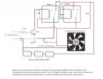
Here is the (badly drawn) circuit done on microsoft paint... because that is all I have...

Note the LED and it's resistor isn't on the schematic on purpose.
One thing about these cheap voltage monitors... as far as I can measure they output about 3.3 volts in very short bursts to activate the chirping speakers. I tapped in to one of the speakers so the other one still works. I had to use an NPN transistor to make the output run the relay.
This rig will discharge 3S batteries all day no problems! Now for the downsides... The relays are 12V and while I can start to discharge a fully charged 2S battery once the voltage drops below 8V the unlatching relay will not actuate causing a potential unsafe condition if ever left unmonitored (which should be never...). However the alarm will still sound continuously even so. I also don't know if the relays would be okay on 4S. I know a car can get up to 14.8V but a fully charged 4S can be upwards of 16V.
I am not an electronic engineer or anything. I tinker with electronics as a hobby so I'm hoping for some feedback to refine my design? Any input or constructive criticism I welcome! Thanks in advance
Currently I have a Electrifly charger that does not have the capability to discharge batteries to storage voltage (or 3.8v per cell). I thought about just using the discharge function and putting a cheap voltage monitor on the balance plug so it alarms when it is time to take it off but number one the charger gets hot when discharging and number two it is plugged in the wall so not portable... I don't want to be stuck inside the room the whole time!
I looked around on the internet to see what other people had for ideas on making a discharge rig to properly store batteries. I did find one DIY rig...but it involved a $30 cell logger device with an alarm output... Which makes it simple but I'm not content with that! Especially when I can use stuff I already have! I decided I want to see if I can make a cheap hobby king voltage monitor turn off my homemade discharge rig.
Here is the prototype... Yes it is made of cardboard... it is a prototype. Yes I have a fire extinguisher with me too

Here is the (badly drawn) circuit done on microsoft paint... because that is all I have...

Note the LED and it's resistor isn't on the schematic on purpose.
One thing about these cheap voltage monitors... as far as I can measure they output about 3.3 volts in very short bursts to activate the chirping speakers. I tapped in to one of the speakers so the other one still works. I had to use an NPN transistor to make the output run the relay.
This rig will discharge 3S batteries all day no problems! Now for the downsides... The relays are 12V and while I can start to discharge a fully charged 2S battery once the voltage drops below 8V the unlatching relay will not actuate causing a potential unsafe condition if ever left unmonitored (which should be never...). However the alarm will still sound continuously even so. I also don't know if the relays would be okay on 4S. I know a car can get up to 14.8V but a fully charged 4S can be upwards of 16V.
I am not an electronic engineer or anything. I tinker with electronics as a hobby so I'm hoping for some feedback to refine my design? Any input or constructive criticism I welcome! Thanks in advance
Last edited:


