Folger Tech 2020 Prusa i3 Build Log

jhitesma

Some guy in the desert
Mentor
So...got my new RAMPS setup today. And...fresh out of the box...same freaking problem.

If you respect me and consider me a trustworthy source of advice you may want to stop reading now. If on the other hand you want undeniable proof that I am human...by all means keep reading.

I win the moron award this week. Turns out that for some reason I had it stuck in my head that Marlin defaults to 115200 baud so that was what I'd been setting things to and trying to connect with. Well, it actually defaults to 250000. No wonder I was getting garbage!

So I seem to have it working again. But I also upgraded to Marlin-RC6 which changed some things in the config file so I'm dialing back in a few settings. And as an extra bonus the new RAMPS I got came with a full graphic LCD so I got that upgrade going for me now too. Plus I have a webcam working on the CHIP so rep-server should do automatic timelapses of prints now...will be testing that shortly.

There is something wrong with my original RAMPS...it still won't connect even at the correct baud and only works printing from SD. So that's something to work out another day.

For now I've got some printing to catch up on!
 

jhitesma

Some guy in the desert
Mentor
Oh cool. Just went to try the new PETG I got from MakerGeeks....and it turns out the white/clear isn't actually white/clear. It's glow!

My daughter is going to love this!
 

jhitesma

Some guy in the desert
Mentor
Well it's printing again...but something must have gotten out of whack because It's overextruding like mad - did a single wall test print with the same settings I was using before. My 0.48mm wall came out 0.91mm :eek: So looks like I'll have to go back and do an extrusion test first since that's crazy far off.

I'm liking the changes in the new rep-server though. It now changes the messages on the LCD and cycles through ETA, ETE, layer count and I think something else while printing. Only problem is it doesn't apply timezone to the ETA so it's in UTC which is a little bit confusing but not the end of the world.

The new graphic LCD is nice...but doesn't really do anything the old 2004 LCD did. Just more lines but shorter lines, and some little graphics on the status page.

The LCD functions have been udpated a bit in RC6 though, there's now a quick easy way to run a PID calibration right from the LCD - just select it and hit go. Runs it and updates the eeprom for you - slick.

Can't really say if there's any improvement in printing with RC6 yet. My first test print was a horrible failure due to a combination of my z-offset changing slightly and the already mentioned overextrusion. Haven't had a print that bad in a LONG time!

So hope to run through some calibrations tonight and then hopefully crank out some good parts. I also played with modifier meshes in slic3r and was able to get the center for my UMBQ to slice with 80% infill where the extra strength is needed - but only 20% in the rest where I'd rather save weight. Can't wait to print it and see how it does...big question is should I print it in black or glow PETG this time :D
 

jhitesma

Some guy in the desert
Mentor
And that explains why I was overextruding. Did a quick test at lunch and confirmed I was getting almost twice as much feed through the extruder as I was expecting. Then I noticed...I had used a config from when I had a 32 microstep driver on the extruder so it was at 200 steps instead of 100 since I'm back on a 16 microstep driver. Doh.

Didn't have time to do a test print because my computer crashed but that goes a LONG way towards explaining the horrible overextrusion I experienced last night!
 

PHugger

Church Meal Expert
Jason, you've been very busy, but you should really stop breaking things!

I have been mostly waiting for parts (small hardware). This week I discovered McMaster Carr. They are fairly local. I ordered some M3 machine screws yesterday and they arrived today with normal shipping. I've been learning how to install heat-set thread inserts. It took me a while to get a system to tighten up the holes in my new ABS extruder. I ended up using some discarded brim material - stuffing a U shaped piece into the hole and then pressing the heated insert into the U. So far so good. I'm also learning how to properly use machine screws in ABS (tap first).

I made some cases for my Raspberry Pi and a Relay Controller
Taz_MG_0353_720.jpg
I have a 30mm fan on the way for the Pi.


I also started getting the new extruder and fan assembly ready.
Here is the stock Taz extruder -
Taz_MG_0350_720.jpg
1 40mm fan with a duct and that tiny squirrel cage on the hot end.


The replacement has 2x 40mm ducted fans and a 40mm ducted fan for the hot end.
Taz_MG_0348_720.jpg


My next step will be to take the extruder apart and put the new one on. I also want to get the Pi running and auto-leveling working. So many fun projects and so little time....


Best regards,
PCH
 

rcflyer729

fpv and rc planes
Hi I have an issue that I thought someone might be able to help me with. I was having an issue where my extruder extruded fine but when I tried to retract it just did not have much power and would only move if I helped it. I ordered some more stepper controllers for my ramps board and installed one for the extruder. Now my extruder only goes one way even when I click retract it still extrudes instead. I put the old driver back on and I have the same issue. I am thinking the best thing to do would be use the E1 port instead of E0 for my main extruder. Is that the best thing to try next or is there something else I can do to fix this issue. If I should swap the extruder port what marlin settings do I need to change? I know the stepper motor is fine since I moved the plug for the x axis to the extruder port and it did the same thing.
 

jhitesma

Some guy in the desert
Mentor
So tried something new with my printer last night. As I'm pretty sure I mentioned before I've been wanting to try printing with nylon since before I even got my printer. But the horror stories of working with it made me decide to take my time and hold off.

Wish I hadn't.

Wow is this amazing stuff! I got a roll of Taulman 910 to try out, it's a natural uncolored nylon. I do have 2 complaints about it so I'll get those off my chest right now. First it's expensive. It was almost $40 for a 1lb spool. That's less than half as much filament as a regular 1kg spool so the cost per g is almost four times what I usually pay for Hatchbox or MakerGeeks filaments. Ouch. Second the small spool has a REALLY tiny opening in the center - without modifying the spool it has no chance of fitting on my spool holder or rolling on the bearings I use. For testing I just set it on the ground and let the filament come off the top naturally.

The spool had a QR code on it and when I scanned it it not only gave suggested temps it also showed the batch code - which was a little disappointing as mine is from early 2015. But the vacuum bag it was sealed in was still intact and well sealed.

One of the big gotchas I've been warned about in regards to Nylon is that it is extremely hygroscopic. Meaning it will absorb water from the air which will cause it to pop and print lousy as the water vaporizes in your nozzle. So I made sure to have a dedicated vac bag to store it in when I'm not using it.

Printing it also requires a bit of care. The temps this spool called for are 245c-250c so an all metal hot end is required to work with it. Additionally getting it to stick to the print bed can be troublesome, talking to others who like printing nylon I was told to get some "garolite" or G10 and use that as a print surface - but also found PVA gluestick on glass as a recommendation. I did order and cut some G10 but haven't tried it yet since that will require adjusting the inductive sensor on my setup. I already had PVA gluestick on my glass so I tried that first and it worked just fine. The person who suggested using G10 said his issue with PVA on glass was it stuck too well and he chipped his glass. You're also not supposed to use a print fan at all with Nylon and avoiding drafts around the machine is also recommended.

Some people report warping issues with nylon but this 910 is supposed to be very good about not warping. I've only done two prints with it so far so I can't really say one way or another yet.

All that said...why nylon? Well. First of all it's STRONG. It's tensile strength is MUCH higher than PETG/ABS/PLA. See the ring around the camera in this photo:

20161003_224016.jpg

That was a 1" single wall test I did and tried to break. Even using some long screwdrivers to get leverage I haven't been able to break it. I did stretch the heck out of it, and I did get a few layers to delaminate but overall it's crazy strong.

At the same time it's also softer which can be a liability. It's softer than PETG and ABS by quite a bit. When I pulled the single wall test off I thought it was still hot and had to cool more because of how pliable it still was. But it was just that it was that soft. However the camera mount itself is quite strong since it has multiple perimeters and infill. It's still not as stiff as a PETG version of the same mount with the same print settings...but it's way more resilient.

Also, Nylon can be dyed with common fabric dyes and even kool aid. So while it's only white you can change the color.

I'm pretty hyped about this stuff. May try reprinting my UBMQ in it even though that thing is already pretty much bulletproof with PLA motor mounts and PETG center.

I also ordered some 0.065" round nylon sold as string trimmer line to play with....I don't expect it to work as well since the diameter probably isn't as consistent and it isn't stored away from moisture...but I'll try drying it out and see how it does since you can get string trimmer line dirt cheap. It's also slightly thinner than 1.75mm but I've heard a number of people who've had success with it.
 

markyoe

Senior Member
Maybe I'll have to try that on my electric longboard build...... Problem is, I have a clone e3d hot end that has a PTFE liner inside. Probably can't remove the liner, but worth a try. I'm working on a carbon fiber electric longboard and I'm going to design a couple mounts for the batteries and electronics to 3D print that will be secured to the board. A carbon fiber cover will hide the mounts and batteries/electronics. I've embedded the power leads in the board that run from the batteries to the electronics. I was thinking about using Proto Pasta CF filament (yes, I know it isn't much stronger than regular PLA) but you might have changed my mind about nylon.

Btw, I post pictures of prints and misc projects on here if anyone's interested: https://www.instagram.com/marcthemaker/ I don't think you need an IG account to see the pics.
 

jhitesma

Some guy in the desert
Mentor
Yeah, the e3d lite and clones with the liner that extends into the melt zone won't handle those temps. You need the all metal version...which still has a PTFE section but it stops higher up above the heatbreak.

Be sure to get a spare nozzle or two if you use the CF Filament, I've heard it chews up nozzles like no ones business. One roll and a non-hardened nozzle is trash.
 

Snarls

Gravity Tester
Mentor
Nice Instagram page markyoe. I like the Eiffel Tower you printed. What model did you use. Ive been wanting to print one myself, but Slic3r always has trouble slicing the cross beams.

I havent done any major projects with my printer lately. Just printing random things every now and then when I need them.
 

jhitesma

Some guy in the desert
Mentor
I'm continuing to have fun experimenting with more exotic filaments :)

After being impressed by Taulman 910 I decided to give string trimmer line a try. I've been looking for some to try locally since I got my v6 but haven't found any round in 1.75ish size, only in 3mm. Then it hit me...Amazon! As I mentioned back in early October I grabbed the cheapest roll of nylon trimmer line I could find off of Amazon for $3....it's not quite 1.75mm - 0.065" which is more like 1.6mm but I gave it a try:

20161005_134019.jpg

First print worked...but wasn't spectacular:
20161005_134113.jpg

The layer bonding was better than the Taulman 910...but surface finish was terrible. I suspected moisture was the issue. So decided to try drying it out. My wife has this "super dri-aid" from when she used in-the-ear hearing aids before switching to behind the ear: https://www.amazon.com/Super-Dri-Hearing-Dehumidifier-Hal-Hen/dp/B000B7I8FQ So I took the lid off of it, and put it in a zip-loc with the trimmer line. Then I put it out in the backyard in the sun for a few days.

Re-printed the test with the same settings and got MUCH better results:
20161017_225122.jpg

The photo doesn't show it well, but the new print was VERY nice while the original was fuzzy. The layer bonding wasn't as good but it still made very usable prints. It's not as strong as the 910 but it's a fraction of the price.

I printed a heart gear keychain in it and it came out wonderful - and is the first one of those I've printed that I'd actually consider using as a keychain since it's durable enough to survive my pocket :)

Like the Taulman it's "softer" as well as strong. I'll have to do a little video showing the heart gears printed in the various materials I've tried (ABS/PLA/PETG/Nylon) and how they compare....

And this week I finally decided to give TPU a try. I ordered a roll of Hatchbox off Amazon for just <$30 since it was the most affordable TPU I found. Oddly enough Hatchbox says it print it at 190-210 even though my research online shows most TPU should be printed at 230-250. Most sources also said to use a 60 degree heated bed...but I went with 70 since some said to run it hotter.

My first test was at 200c and the bed at 70c with PVA gluestick. It printed amazingly well:
20161109_213253.jpg

One of the cleanest first prints I've ever had! Oddly enough though it was very slightly underextruded even though I expected it to be slightly overextruded based on my slicer settings. (I had my filament diameter set to 1.70 even though it measures 1.75...well...kind of...more in a second.) I was expecting 0.48mm walls and got 0.46mm instead...Not perfect but pretty darn close. The layer adhesion is crazy strong. And the flexibility is ridiculous:

20161109_213314.jpg

The material itself is very...weird. That's really the best I can put it. It's almost like a rubber band. Feeding it into my extruder was a bit tricky, but thankfully the extruder I'm using is fairly well suited to flexible filaments since there's very little space between the PTFE tube and the drive gear:

20160320_141817 (1).jpg

That was actually one of the reasons I started using this extruder in the first place, it's just taken longer than I anticipated for me to get some flexible filament :D

Back to the weird. I mentioned that it measured 1.75mm pretty accurately...but it actually doesn't. It's not very round at all. At almost any point on the filament I can measure it at 1.75mm...but twist the calipers a bit and it's not. I don't think it's that the filament wasn't extruded well..it's just that it's soft and has taken a bit of a set from being wound on the spool and then put in a vac bag. I wonder if this is why I got slight underextrusion when I was expecting overextrusion.

The tensile strength also appears to be very strong. I extruded some into the air to purge my nozzle and then stretched it and holy cow did it stretch a lot before breaking. it did turn white and loose it's elasticity, but took a lot more stretching after that before actually breaking.

It also isn't sticking to my elmers purple glue stick as well as I expected. I may try some hair spray or blue tape with it. My first test stuck fine while printing...but immediately after before the bed could really cool it came off just by touching it. My second test a stretchlet (http://www.thingiverse.com/thing:13505) didnt' stick at all and just made a mess. My third attempt (the stretchlet again) failed but was a slicer failure...for some reason sli3er does not slice that model well and leaves big gaps :( A fresh coat of glue stick kept it on just fine.

Fourth attempt I tried a different stretchlet (http://www.thingiverse.com/thing:445476) and tried something else new printing it in spiral vase mode. It came out great. Sorry I don't have any photos but it's gorgeous. No seam, smooth layers...stretchy...just perfect. And again fresh glue stuck it fine.

Really looking forward to experimenting with this material some more. I want to tackle printing a RC car or tank and will use this for the tires or treads :) I'm also curious to see how it does printing more "solid" objects. I know a lot of people like it for FPV camera mounts and pods....but the pod I'm designing on my 3D printed quad is structural so I don't think this would work for it:
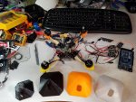
20161022_092245.jpg
 

wilsonb

New member
I find it strange you have trouble sticking the flexible filament. I print ninjaflex with cold glass and gluestick on one machine and just blue tape on the other. The biggest challenge for me was getting a consistent extrusion. I consider you a lucky user if bed adhesion was the problem.


I know most of you guys use RAMPS boards with an arduino mega for a controller. Here is a pretty good upgrade option without breaking the bank:

https://www.kickstarter.com/projects/1245051645/re-arm-for-ramps-simple-32-bit-upgrade

The RAMPS fits right on this and you get a 32 bit controller. Seems like magic.
 
I'm thinking of getting this kit but I have some questions:

How difficult was it to assemble and set up this? I've never done a project like this before...

Are there any upgrades/modifications that you recommend that I should do?

Should I get the aluminum or acrylic version? The folger tech website says that the acrylic version has a 1" taller build volume for some reason.

And Markyoe did you print that ukulele on your Instagram with this printer?

Thanks!
 

jhitesma

Some guy in the desert
Mentor
I find it strange you have trouble sticking the flexible filament. I print ninjaflex with cold glass and gluestick on one machine and just blue tape on the other. The biggest challenge for me was getting a consistent extrusion. I consider you a lucky user if bed adhesion was the problem.

I think the problem was the glue on my glass was old and dusty. I cleaned the glass and put on fresh glue stick and haven't had an issue since. Printed the pod for my 3D printed quad yesterday and came out pretty well. Still having a few retraction issues causing some blobs here and there on travel moves, but overall not bad:

20161112_211345.jpg

Going to have to rethink my design though if I want to go with TPU for the pod :( The nut traps don't work at all in TPU (they were almost too tight in PETG and PLA but in TPU the nut just spins since the TPU is so soft) and the bottom of it is too soft so it doesn't give the frame the rigidity that the PETG/PLA versions do. Also the camera mounts are too soft and flexible so don't hold the camera very well. I could design something that's half TPU and half PETG...but...I'll probably just stick with PETG or Nylon on this part for now.

I know most of you guys use RAMPS boards with an arduino mega for a controller. Here is a pretty good upgrade option without breaking the bank:

https://www.kickstarter.com/projects/1245051645/re-arm-for-ramps-simple-32-bit-upgrade

The RAMPS fits right on this and you get a 32 bit controller. Seems like magic.

Interesting...but It's the RAMPS for than the Arduino Mega that I'm not impressed by. The mega has plenty of power for a Cartesian printer IMHO - it's dealing with deltas that the Mega is lacking. The RAMPS on the other hand is just very marginal. The power circuitry in particular could really be done a lot better. I'd rather go with a MKS if I was looking for an upgrade...but I'll take a closer look at this tomorrow just out of curiosity if nothing else ;)
 

jhitesma

Some guy in the desert
Mentor
I'm thinking of getting this kit but I have some questions:

How difficult was it to assemble and set up this? I've never done a project like this before...

Hard to say since it depends on your experience level. I had never built a 3D printer before...but I had built a small X/Y motion platform from CD drive components - not that the experience helped much (It used radically different hardware and software.)

I got mine built in under 24 hours but it was on vacation and I was able to totally focus on it to get it done in that time. The instructions aren't good - there are known issues with them and the parts supplied don't match the parts in the instructions 100%. Some research (this thread is a great place to start) is definitely necessary. But the actual assembly isn't that bad. For the most part the frame self-aligns - the big exception being the Z stepper mounts which will pull the frame out of square if installed as the instructions suggest.

For me the hardest part was organizing all the hardware and determining which screws to use where since the instructions don't match the hardware and some things there's just enough of while others there's way more than you need and some hardware was included that wasn't even used anywhere in the kit. So it's almost impossible to make sure you have everything before you start assembly.

Are there any upgrades/modifications that you recommend that I should do?

There are quite a few possible...but I got very good results with the stock setup. I did swap my Z axis to lead screws (about $20 on banggood) within the first week and I added an inductive sensor for auto level (which was why I wanted the lead screws...with the extra Z motion auto level brings the stock threaded rod can wear out rather quickly.) I also installed risers that lift the Z steppers higher to get some extra build height, but haven't really needed that extra height yet almost a year later. I still needed the risers because installing the larger couplers for the lead screws was much easier with the risers in place.

I've also changed my hot end to a e3d v6 because I wanted the all metal design to allow me to print Nylon and other higher temp materials. There are mounts to use the v6 with the stock extruder - but I wasn't super happy with the stock extruder and it's lack of tension adjustment. Before I put the v6 on I upgraded to a metal MK8 extruder I got off ebay for $12 that had a tension adjustment and actually in some ways I preferred that to my current setup. I just couldn't find any mounts to make the v6 work with that extruder or I'd still be using it. I was able to get more consistent tension and smoother printers with that than with my current extruder. On the other hand my current extruder is way better for flexible filament which is nice now that I'm printing with some.

Should I get the aluminum or acrylic version? The folger tech website says that the acrylic version has a 1" taller build volume for some reason.

I would go with the 2020 aluminum for sure. The acrylic was more expensive by a few dollars and isn't quite as rigid. There have also been reports of the heated bed warping it's support on the acrylic version. You can gain back an inch of build height on the 2020 version with the motor risers I put on mine - but again I haven't really done anything that needed that extra height.
 

PsyBorg

Wake up! Time to fly!
Ok heres a challenge for ya. Print the base frame in harder PETG or PLA so your nuts are secure and properly held. Then print a TPU pad to set that on. Then print around the PETG / PLA part and encase that in the TPU by building pff the pad.

(mind you I have ZERO knowledge of 3d printing so that probably can not be done because of bonding a cooled part with fresh print)
 
Hard to say since it depends on your experience level. I had never built a 3D printer before...but I had built a small X/Y motion platform from CD drive components - not that the experience helped much (It used radically different hardware and software.)

I got mine built in under 24 hours but it was on vacation and I was able to totally focus on it to get it done in that time. The instructions aren't good - there are known issues with them and the parts supplied don't match the parts in the instructions 100%. Some research (this thread is a great place to start) is definitely necessary. But the actual assembly isn't that bad. For the most part the frame self-aligns - the big exception being the Z stepper mounts which will pull the frame out of square if installed as the instructions suggest.

For me the hardest part was organizing all the hardware and determining which screws to use where since the instructions don't match the hardware and some things there's just enough of while others there's way more than you need and some hardware was included that wasn't even used anywhere in the kit. So it's almost impossible to make sure you have everything before you start assembly.

There are quite a few possible...but I got very good results with the stock setup. I did swap my Z axis to lead screws (about $20 on banggood) within the first week and I added an inductive sensor for auto level (which was why I wanted the lead screws...with the extra Z motion auto level brings the stock threaded rod can wear out rather quickly.) I also installed risers that lift the Z steppers higher to get some extra build height, but haven't really needed that extra height yet almost a year later. I still needed the risers because installing the larger couplers for the lead screws was much easier with the risers in place.

I've also changed my hot end to a e3d v6 because I wanted the all metal design to allow me to print Nylon and other higher temp materials. There are mounts to use the v6 with the stock extruder - but I wasn't super happy with the stock extruder and it's lack of tension adjustment. Before I put the v6 on I upgraded to a metal MK8 extruder I got off ebay for $12 that had a tension adjustment and actually in some ways I preferred that to my current setup. I just couldn't find any mounts to make the v6 work with that extruder or I'd still be using it. I was able to get more consistent tension and smoother printers with that than with my current extruder. On the other hand my current extruder is way better for flexible filament which is nice now that I'm printing with some.


I would go with the 2020 aluminum for sure. The acrylic was more expensive by a few dollars and isn't quite as rigid. There have also been reports of the heated bed warping it's support on the acrylic version. You can gain back an inch of build height on the 2020 version with the motor risers I put on mine - but again I haven't really done anything that needed that extra height.

Thanks! How do you build the printer with the lead screw, and what are the "risers for the z axis? Can you link me to the lead screws? Also how does the auto bed leveling work? I know that is an upgrade I definitely want to do. :D

I think I found a list links to the thing you talked about, are these them?
https://www.thingiverse.com/groups/vv-printing/topic:4379

Also should I make one of those part cooler ducts?
 
Last edited:

jhitesma

Some guy in the desert
Mentor
Ok heres a challenge for ya. Print the base frame in harder PETG or PLA so your nuts are secure and properly held. Then print a TPU pad to set that on. Then print around the PETG / PLA part and encase that in the TPU by building pff the pad.

(mind you I have ZERO knowledge of 3d printing so that probably can not be done because of bonding a cooled part with fresh print)

The problem is space...there's barely enough room to get the outer nuts in as it is. So if I have to do two plates out of two materials...things get even tighter. And making the pod bigger runs into other issues with the rest of the design :( Printing around an existing part doesn't really work either since the nozzle has width to it and would interfere. And printing on top of an existing part would be tricky since getting a first layer to adhere is tricky already without doing it on top of a printed surface in another material.

I could redesign it so I keep the original lexan plate for stiffness and then the TPU top attaches somehow...just not sure I want to go that way. We'll see how a PETG or Nylon top holds up first since that's going to be easiest.
 

jhitesma

Some guy in the desert
Mentor
Thanks! How do you build the printer with the lead screw, and what are the "risers for the z axis? Can you link me to the lead screws? Also how does the auto bed leveling work? I know that is an upgrade I definitely want to do. :D

Don't really have any links handy...I did this back in January and probably posted links in this thread at the time I did it :) If not I may have some on my blog at nevermindthesand.com If I had more time right now I'd search some up for you but this is a pretty crazy month for me and my daughter was home from school with a cold today which cost me even more productivity so I'm a little tight on time.

I built mine bone stock at first...and then used it to print the parts for the upgrades. To add the leadscrews you basically replace the two printed Z carriage parts with ones designed to fit leadscrews instead...there are several different designs out there. I went with one from moosteria which had the right side modified to improve the Z-endstop...but since I switched to auto level never actually used that feature. The risers this is the best set to use: https://www.thingiverse.com/thing:1288802 the originals you linked to from wderoxas have a minor flaw where only 2 of the 4 holes are properly countersunk.

The autolevel can work several ways. YOu can just modify and end stop mounted to a 5g servo but that's a lot of mechanical stuff to deal with so it's less accurate and more to go wrong IMHO. There are capacitive sensors but they're expensive and I'm not a fan of capacitive sensing in general since so much can affect it. There's also the bltouch which is popular and works similar to an end stop on a servo but is entirely self contained and less finicky so more accurate. I'm using an inductive sensor (and details about that are definitely on my blog and were shared earlier in this thread.) The big problem with an inductive sensor is it needs metal to trigger it. I use a piece of heavy duty aluminum foil under my glass - though some people have reported not getting their sensor to work with that little metal. Mine almost worked just off the metal traces in the heated bed even through the glass - but I got artificially high readings in some spots when there was a screw head for the Y carriage mount near the point I was probing. Adding the HD foil gave it something consistent to trigger off of. I originally used some 28ga (IIRC) steel sheet from the hardware store...but the edge curled when I cut it so it didn't sit as flat and gave me one corner that read artificially high.

You don't need autolevel, I just prefer it since manual leveling got old and every time I cleaned my glass it would go out of whack. It varies from machine to machine - and on mine the stock leveling screws were just barely long enough in one corner which was why I had issues keeping level consistent. I still manually level to get it as close as possible - but haven't had to bother with fine tuning it in months.

Also should I make one of those part cooler ducts?

Not needed at all for ABS and some other materials. But for PLA and PETG it makes a HUGE difference. Mine isn't optimal and which one to use varies greatly depending on the hot end/extruder you use.

I have a few mounts I designed on thingiverse for mounting inductive sensors and layer fans to the stock extruder that are fairly popular based on the download counts (though few people post makes of them :( )

This was the first and simplest mount I designed and used:
http://www.thingiverse.com/thing:1267183

I actually still have about a dozen usable test prints of it laying around...but would cost too much to ship them to someone to be worth it. Plus anyone who needs one should already have a printer to make their own :D