1/6 SE5a: Building scale with DTFB

willsonman

Builder Extraordinare
Mentor
I had a request to show an update online of my progress on ANOTHER project I have going. Awhile ago I built a 1/6 scale SE5a that met its demise while encountering a light pole at a park. This was when I realized my eyesight was going a little and my depth perception was the issue. I wanted another one and decided to build another but lighter! Building lighter will allow for more challenges with building and allow for additional scale features. Fine by me!

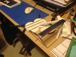
First we have the makings of the landing gear and wheels. Landing gear is coat hangar wire that has been soldered to shape. Fairings are DTFB attached with gorilla glue and covered in tissue and WBPU. Ready for paint. Wheels will be DTFB core with PVC on the outside to help support the axle tube. Tire is a section of a gasket I salvaged. It is neoprene. You can also see in this picture three of the four interplane (IP) struts that go on the wings. These are coat hangar wire again and will be fared the same way as the landing gear.
IMG_0236.JPG

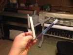
Here is another image of the landing gear. Scrap tissue but once painted you will never see the printed portions.
IMG_0237.JPG

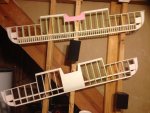
WINGS! Yes, each piece was hand cut. The spar is DTFB and I may reinforce with carbon fiber. I wanted the scale ribs as well as the sub-ribs on the leading edge. Much more work to be done there. The bottom wing has a covering of posterboard that will be glassed for hardness for a better mount to the fuselage bottom. All four ailerons will be driven by a single servo in the bottom wing. I'll explain that as I get there. The top wing has the majority of the cap strips in place. These are scale and reinforcing. They give rigidity to the wing and serve to give the scale rib stitching once covered in doculam. The strips are 110# card stock that has had thread glued to it in a horizontal pattern at the scale spacing. I have to make more so I will explain how I did that when I make more. Wings are roughly 53" in span.
IMG_0233.JPG

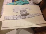
Last night I started on the fuselage. Here are the formers cut out and the bottom with markings for where the formers are to be glued. This worked well the last time and I will modify the engine location to mount the battery in the TOP of the fuselage rather than the bottom. A hatch will be cut (obviously) but the ease of battery connection is my main concern there.
IMG_0234.JPG

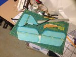
I salvaged the V-stab/rudder and the H-stab/elevators from the last plane. Single layer of DTFB with hard balsa at the hinge points. Covered in tissue and WBPU and hinged with strips of solartex scraps I had laying around. Control surfaces are pull-pull style to help keep the back end light. Spider wire fishing line is my line of choice for this as it is SUPER light and strong. It also does not expand and slack when the summer heat is on. You can also see the hard balsa tail skid in this shot. Also salvaged from the old plane.
IMG_0235.JPG

Power will be a Tacon Bigfoot 15 motor and a 40A Detrum ESC swinging an old timer top flite 13.5x4 wood prop. Shooting for room for a 2200 mAh 3S battery for very long flight times on this setup. Lots of thrust... no speed. 5-9g servos. Will probably go with a metal gear 9g on the ailerons. I should have plenty of room for my 1/6 scale full-body pilot. I'll keep posting as I build along.
 

willsonman

Builder Extraordinare
Mentor
Thanks! I forgot to mention that I am using the J.D. McHard plans that can be downloaded over at Hip Pocket. Scaled them up to 1/6. They are a good set. I'm using the airfoil from Aerodrome RC that was on my 1/6 Tummelisa plans. Its a great flat-bottom airfoil. Lots of lift with minimal drag.
 

willsonman

Builder Extraordinare
Mentor
Here are a couple of shots of the last plane prior to maiden. I used the hotwire solid core wing design before.
 

Attachments

  • IMG_7617a.jpg
    IMG_7617a.jpg
    216.5 KB · Views: 27
  • IMG_7618a.jpg
    IMG_7618a.jpg
    189.8 KB · Views: 34

willsonman

Builder Extraordinare
Mentor
First peel back the paper from the fuselage base on the side to be glued only and glue the formers at the indicated positions. Dont worry too much about the angle as long as it is straight across and centered.
IMG_0240.JPG

Then do the same with the side cheeks. This is where you set your former angle. Mark the cheek at the top and tape in position while the glue dries. I am using gorilla glue here. It expands nicely and makes super strong joints. Since it expands you only need a little. For tape I use aluminum ducting tape. The adhesive is very strong for holding the pieces in position properly.
IMG_0241.JPG

The paper on the outside of the fuselage bottom and sides (cheeks) will be removed later. Keeping it on for now helps to make sure everything stays straight. A twist in the fuselage will create headaches when you go to put on the H-stab and wings. They will not line up well.
 

willsonman

Builder Extraordinare
Mentor
Lol... its not strong. You have to reinforce it. The real advantage is that its easier to work with and cheaper. If you screw up in the scratch building process... who cares? It builds lighter if you are smart. I'll be using my standard WBPU and tissue method. I really do not have a weight goal but under 20oz./sq.ft. would be a great wing loading to achieve. A real floater. I have lots of lightweight glass so I may end up doing that so I do not have to sand as much. Its just more expensive for the airframe. I'm trying to use mostly off-the shelf items that are common. CF rods and polystyrene tubing will probably be the only exception to this. I plan on using a standard fishing line, cotter pins, wire coat hangar, DTFB, tissue paper, WBPU, Gorilla glue, wood glue, doculam, as well as other standard flight gear stuff for servos and motors. The goal is cheap... but with the scale detail.
 

willsonman

Builder Extraordinare
Mentor
So here we have the butt-end of the plane. I cut and shaped a solid piece of foam for the H-stab to be glued onto. You can also see my motor and mount along with the prop on it. I'm working out how to mount it.
IMG_0243.JPG

I measured the distance from the front of the fuselage to where the leading edge of the wing needed to be. I traced the airfoil shape on both sides and cut the foam away.
IMG_0244.JPG

I started making the rear cabane strut. This is just a coat hangar bent to shape. I roughed up the area to be glued and used an overage of gorilla glue. It is holding very well. I bent the additional fold at the bottom to that any additional torsional load will be spread onto the lower wing, not just the fuselage.
IMG_0245.JPG
 

willsonman

Builder Extraordinare
Mentor
I had a major distraction this weekend. I met up with a friend and I procured a Top Flite AT-6 Texan. Its a shoe-in for electric conversion so I spent time relieving the slimer motor from its duty in preparation for electric. I will be on this build again this week.
 

willsonman

Builder Extraordinare
Mentor
Last night I spent quite a bit of time on the motor mount. In planning ahead for the top placement of the battery I needed to get the motor height to the scale location. There were two different motors used and they each had a different height protruding from the front. The first mounts approximately 1/4 of the total height from the top. The other mounts 40% of the total height from the bottom. I chose the second since it gives much more room for the battery and hopefully will allow me room to place the battery over top of the motor. My measurements indicate this but we shall see after I cover and cut away the hatch.

Since the bottom of the fuselage has a bend I measured the length of the motor up to where it would protrude through the front of the fuselage. I measured back on the plans and down to get the correct height of the mounting plate. Since the mount will be adhered with gorilla glue I wanted more adhesion surface area. I cut 3/8 hard balsa stock and mounted them to the front and rear of the sides with TitebondII. I drilled holes in the bottom to get some air flow over the ESC which will be installed aft of the motor.

I'll work on getting the motor mount glued this evening as well as make some headway on the landing gear. I need to cut the wheels to the correct diameter and make up mounting plates for them so they do not destroy the foam after a couple of hard landings. I'll use Popsicle sticks.
 
Last edited:

willsonman

Builder Extraordinare
Mentor
Ok, here is what we are making
IMG_0252.JPG
Core is two laminated pieces of DTFB. I used hot glue to seal the ends and prevent the foam from delaminating from the paper. Then glued together. After that I applied the polystyrene (for sale sign from hardware store) sheet to the foam for reinforcement. Its slightly oversized to help the "tire" stay put and make a clean finish. The axle is polystyrene tubing from the hobby store. I'm considering placing hard balsa rings around the axle tube for additional reinforcement. Thoughts?
IMG_0253.JPG
The neoprene gasket cut to length.
IMG_0254.JPG
I used hot glue to connect the neoprene ends together. Applied a liberal amount of hot glue to the foam cores and stretched the "tire" over the lip and rolled it a few times to spread the glue evenly.
IMG_0255.JPG
And on the landing gear. (the gear was taped in place for this shot)
IMG_0256.JPG
And the motor mount glue drying. As you can see there will be some room above the motor for the battery to lay flat. Once the hatch is cut I will trim away the formers to allow room for it.
IMG_0257.JPG
 

willsonman

Builder Extraordinare
Mentor
Landing gear mount: First cut the width of the popsicle stick for the double lamination. Then cut away only a half thickness of foam for the single stick.
IMG_0258.JPG
Glue the single stick to the foam and then the double lamination.
IMG_0259.JPG
Rinse, repeat.
IMG_0260.JPG
Prep the mounting screws. The plastic pieces are electrical wire hold-down thingers from the hardware store. They come with nails so remove the nail and substitute screws.
IMG_0261.JPG
Cut away the expanded gorilla glue and sand the foam flush.
IMG_0262.JPG
To allow more time for the glue to harden I bent up another coat hangar for the front cabane struts and glued into position. The single foam piece is only wedged in there to keep the wire in position while the glue dries.
IMG_0263.JPG
Screw down the landing gear.
IMG_0264.JPG
Progress shot. With how lightweight the fuselage is at this point the sanding block had to be placed. The motor weighs way more than the entire fuselage. I also cut the groove for the tail skid so that is in place for this shot but not glued. I want to cover the plane before I do that.
IMG_0265.JPG
 

willsonman

Builder Extraordinare
Mentor
Servo rails in using balsa. Forward wing mount with wood and polystyrene tubing to accept hangar wire pegs from the wing. Rear mounting in with wood and nylon bolts. Installed the sub-ribs on the bottom wing.
 

Attachments

  • IMG_0307.JPG
    IMG_0307.JPG
    1.9 MB · Views: 20
  • IMG_0309.JPG
    IMG_0309.JPG
    1.7 MB · Views: 23
  • IMG_0310.JPG
    IMG_0310.JPG
    1.5 MB · Views: 24
  • IMG_0308.JPG
    IMG_0308.JPG
    1.5 MB · Views: 18

willsonman

Builder Extraordinare
Mentor
Elevator and rudder servos installed. The picture of the wing is a bit blurry but you can see I've installed the bell cranks and the wire that runs through the wing driven by a single servo. I also got the ESC programmed and installed.

After hearing about what happened to David's Spitfire at SEFF I am re-thinking the wing spar. Given that it is foam WITH the paper on it I am fearing the same will happen to these wings. I am thinking about carbon fiber arrow shafts. While overkill, its cheap. At $3 a shaft its hard to beat over smaller diameter CF rods that will be sufficient. I will have to notch the seams at the dihedral points.

I really need to move on the fuselage so I'll be making my pull-pull tubes this evening from coffee stirrers. You have to reinforce the foam as the lines, when taught, will slice through the foam. The plastic will also create less friction and make the servos work less. Once the lines are run I can close up the top of the fuselage.
 

Attachments

  • IMG_0311.JPG
    IMG_0311.JPG
    1.5 MB · Views: 26
  • IMG_0312.JPG
    IMG_0312.JPG
    1.9 MB · Views: 15

LordVader

Member
This looks awesome. I am subscribed. This opens up a lot in the hobby, can take virtually any plans and build from DTFB. Just awesome. Thanks for sharing.:D
 

willsonman

Builder Extraordinare
Mentor
Which one!? LOL. The B-17 is on hold for now. I realized that I could not finish it in time for David's farewell and I thought this project would contribute more to the community since its DTFB and building scale. The J-22 I've not made any more progress on. I've not started a thread for that yet. The fuselage is in bones.

No progress last night. Back was hurting pretty bad. I just wanted to sit. Not sure why. Good news is that I checked out my amazon prime to order a new filter for our fridge. Found out what I'm getting for my birthday next week! Both guns for this plane are hidden somewhere in the house. Williams brothers makes very scale stuff. I've used their Le Rhone motor as a dummy for my O-1 Tummelisa. Super excited to have them soon.
 

willsonman

Builder Extraordinare
Mentor
Got the guns! They both went together very easily last night. As with all plastic models there was some trimming involved but I've always found that using plastic cement sparingly gives the best visuals. I've assembled the kits in full. The Lewis gun will more than likely not change. I need to make the Foster mount and then I'll mount it to the upper wing. The Vickers gun will probably need to have parts removed. Namely the sight. Need to do more research on that. Depending on the fit the ratchet mechanism may be removed to fit neater inside the fuselage. Overall very happy. It funny though. I feel like the two guns weigh more than one entire wing at this stage.

I needed to pick up some cement for the guns and as I perused the hobby store I stopped by the CF section. I picked up some CF rods that have rectangular cross sections. Reason: To make the dihedral strong. Using tubes would give a lot of strength. CA and CF play VERY nice together. I can simply cut the CF pieces and CA them together at the proper angles and insert the CF spar into a slot I can dremel out. I'll rough sand and use gorilla glue. It will be strong and super light. Using tubes I would risk weaker joints without using a brass or aluminum joining tube. Too complicated. By placing the spar with the long side of the cross section vertical I'll get the same amount of strength and then get the ease of construction I am looking for. I'll explain this more in pictures as I get to it.
 

Attachments

  • IMG_0324.JPG
    IMG_0324.JPG
    1.6 MB · Views: 17
  • IMG_0325.JPG
    IMG_0325.JPG
    1.4 MB · Views: 19
  • IMG_0326.JPG
    IMG_0326.JPG
    1.8 MB · Views: 10
  • IMG_0327.JPG
    IMG_0327.JPG
    1.5 MB · Views: 12
  • IMG_0328.JPG
    IMG_0328.JPG
    1.7 MB · Views: 13