Here we go again - Endurance II

quorneng

Master member
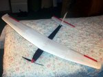
Sad to say but I lost my original very successful Endurance.
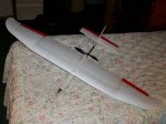
NewTips.JPG
Too high and too far away I briefly lost sight of it when 'edge on' in a turn and I never saw it again. :( Drat!
The 'follow on' Super Endurance
GluedWing.jpg
Flies well enough but demonstrated conclusively that cheap Li-ion batteries actually have nothing like (only about 15%!!) the capacity it 'says on the tin'! :mad:
Unfortunately 'quality' Li-ion cells end up considerably more expensive than the equivalent capacity LiPo.

The original Endurance was developed over quite a period of time with many changes so I wondered if I sat down and re-designed it from scratch might it be possible to do even better?
So in the best traditions of a movie follow on - Endurance II ;) with the same battery, motor, 48" span and as a similar pylon wing pod and boom pusher.

First the wing.
Using Depron it is possible to build a wing with swept up turned tips as used by most 'moulded' foamies. Now is this design aerodynamically more efficient or is it done simply because it is possible to do it cheaply and it looks neat. In theory a wing that controls and limits the tip vortex can be more efficient as it behaves as if it had a higher aspect ratio so the proposed Endurance II wing.
WingPlan.jpg
Light with a broad chord to give a low wing loading.
Something else I have wanted to try is 'direct acting' ailerons with no linkage whatsoever. Mechanically efficient and with nothing 'dangling in the breeze'!
It will also use a V tail.
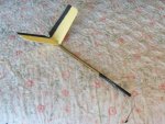
Vtail.JPG
Such an arrangement means virtually none of the airframe is directly in the relatively fast moving prop wash so it should reduce the drag.

Will it all actually make any difference?
I have my doubts so I will just have to build it and see.
 

Craftydan

Hostage Taker of Quads
Staff member
Moderator
Mentor
+1.

Looks like a good start as usual. So am I seeing right, Elevator-only V-tail?
 

quorneng

Master member
Craftydan
That is correct, bank and yank. The V tail is used simply to keep the tail feathers out of the prop slipstream.
The geometry to move both elevators from a single servo link is, lets say, 'interesting' and relies on the sideways flexibility of the elevator horns!
Note the angular difference between the horns from full down (top) to full up (bottom).
ElevLink.jpg
With the micro servo buried in the LH tailplane it does make a neat (and well protected) installation.
 

Craftydan

Hostage Taker of Quads
Staff member
Moderator
Mentor
Very clean and light.

Looking forward to seeing how those ailerons turn out :)
 

quorneng

Master member
The unusual shape of the wing tip (for a built up structure) and the direct acting servo needed to be 'proved' so one wing tip (12") was started.
The preformed 2mm Depron lower wing skin with its all Depron internals.
TipUndrSkin.JPG
The wing tip is a true monocoque structure with no spar just a shear web.
The formed top skin added.
TipTopSkin.JPG
A close up of the 3.7g aileron servo which just fits in the space available.
AilServo1.JPG
The servo arm is glued directly to the aileron so there is no retaining screw and has to rely on the aileron outer hinge to stop the servo arm working off the spines. Fortunately on this servo the arm is a tight fit on the splines.
The aileron has a substantial balsa hemispherical leading edge which also acts as a torque tube.
BalsaLE.JPG
The outer pin (literally!) hinge made up of two sheets of thin plastic.
PinHinge1.JPG
One surface is glued to the outer edge of the aileron. The other is glued into a fine slot in the wing. The pin is driven into the aileron balsa leading edge.
Finally small triangular balsa 'shrouds' are glued in place to minimise the aileron gap.
AilShroud.JPG
With care the gap could be kept to less than 1/4 mm.
The aileron under test using a servo tester.
As I hoped note the complete lack of any external linkage.
The servo tester actually moves the servo to nearly 125% of travel and the action is a bit smoother than the You Tube video suggests.
So far so good now I have just got to build the rest of it!
 
Last edited:

quorneng

Master member
Next is the 24" wing centre section.
Built flat with no dihedral to eliminate a joint at the point of maximum bending. It also has a tapered hard balsa spar.
CntrSect.JPG
The next problem was how to run the servo wires to the centre of the wing after the top skin was in place.
Drinking straws provided a light weight solution.
CableRuns.JPG
The LH tip added to the centre section. It is simply glued on.
CentreLH.JPG
The completed 48" span wing under a load test.
18ozTest.JPG
Supported at it tips the wing easily carries the two 9oz steel blocks at its centre. Certainly not its ultimate load but even so this load is still nearly twice the weight of the complete fuselage, motor and battery.
The bending stress on a wing supported at its tips is over 3 times that as if the same weight was uniformly distributed over the whole area which it tends to be in flight.
This test suggests the wing will plenty strong enough to handle a 6g manoeuvre or put another way mild aerobatics despite the fact the battery will constitute nearly half the weight of the complete plane.
 
Last edited:

quorneng

Master member
Next come the wing pylon. It is built in the same way as a wing but in normal flight it has little bending load however it can be subject to a considerable twist if, say,a wing tip touches on landing so it has a 'square' balsa/Depron/balsa spar.
PylonSpar1.JPG
The balsa 'fingers' are glued to either side of the main spar.
PylonSpar3.JPG
The ESC is housed in the rear part of the wing pylon.
PylonESC1.JPG
The ESC is 'bare' with no heat shrink. The heat sink is mounted flush with the pylon wing skin.
PylonESC2.JPG
With the motor in place the rear part of the wing pylon can be glued in place.
MotorESC.JPG
The bottom of the pylon spar continues into the fuselage and also locates the front end of the tail boom.
As the direct drive ailerons require the use of sub trims to exactly centre the ailerons it has to use a 2.4 radio and this requires the possibility of 're binding' so the Rx has to be accessible. On 35meg I am quite happy to build the Rx in permanently as it either works or its broke!
 

quorneng

Master member
The wing pylon complete.
Pylon2.JPG
The Orange 4ch featherweight rx fitted 'through' the pylon spar in iys own little Depron box.
RxInstall.JPG
Done like this the radio can be drawn forward into the battery compartment to re bind if necessary.
The fuselage pod and tail boom added.
FuseTail1.JPG
The fuselage nose is over long to allow the battery to be accurately positioned to achieve a suitable CofG.
 

Foam Addict

Squirrel member
Excellent work Quorneng! However, those feather-weight receivers are also short range. I'd guess less than 200 ft, maybe 250 ft on a good day. I have had 3, and all have lost link at less than 300 ft. I failed to range test the first one I bought, and had a flyaway just after launch.
Still great build! I just wanted to make sure it didn't turn into a pile of foam scraps due to a receiver failure. :)
 

quorneng

Master member
Foam Addict
The rx actually came out of my Depron Super Cub and in that it went well beyond 200ft (in fact as far as I could safely see a 40" plane) with my DX6i.
I do take the point that these Rxs don't have a satellite but by mounting it below the ESC and midway between the widely spaced motor and battery I hope it will be less likely to get shielded from the Tx, regardless of the planes orientation given the sedate nature of endurance flying. ;)
 

quorneng

Master member
Endurance II finished with a light weight paint job.
CompltTop.JPG
To achieve a suitable CofG the nose has been shortened by quite a bit.
The underside of the yellow surfaces are painted black as it stands out better against both cloud or blue sky.
CompltUnder.JPG
But it is still pretty hard to see when edge on!
So far the weather has not been suitable for any accurate consumption tests but this video does give an idea of how it flies.
The first high fly past gives an idea of typical endurance flight. The later part of video flying closer to the ground for the benefit of the camera does demonstrate that it is surprisingly nimble.
 
Last edited:

quorneng

Master member
The object of the Endurance was..er.. endurance and the only way to find what it might be was to test it.
Clearly finding its absolute endurance would be exceedingly boring and ultimately expensive as any LiPo does not like giving its full capacity and 5000mAh one are not that cheap.
The bgest solution is to fully charge the battery, fly for an extended period (say an hour) and then see how much is required to bring the battery back up to full charge.
As built the result was
Flight duration 66 minutes and it required 1280mAh to recharge the battery.
1.260x60/66 = 1.16A average consumption.
Not bad but not quite my 1A target.

The up swept tips may look neat and provide a degree of stability but I am not convinced they are particularly efficient with some the surface area generating surface drag for no lift.

I decided to use a tip design similar to that I used on the original Endurance.
It has the same span but the underside is now flat.
Mk3Tip2.JPG
The leading edge is swept back as before but the trailing edge is 'bulged' to provide a continuous radius.
Mk3Tip1.JPG
Today's early morning flight in absolutely still conditions lasted 64 minutes and required 1023mAh.
1.023x60/64 = 0.944A average consumption.
As it uses a 5000mAh battery it has a theoretical duration of 5 hours! :)
 

SOOFLY

Senior Member
Yes. They are excellent. I've used the micro ones to altitudes where my 1.5 m gliders were difficult to see, and no problems whatsoever.

I can concur. I have a bunch of the micro lemon receivers that I routinely fly until almost out of sight with no problems.

Great looking plane and outstanding flight times.
 

quorneng

Master member
After 2 more successful 1 hour flights I managed to loose sight of it when 'edge on'. Fortunately a dog walker saw it land but the impact was severe and the ground very hard.
Crash1.JPG
Quite a bit of a rebuild required!
The severity of the impact can be seen from the state of the solid Depron nose block!
NoseCrush.JPG
During the rebuild I took the opportunity to replace the V tail with conventional 'cruciform' tail of slightly larger area, but also slightly lighter.
Rebuild3.JPG
The elevator servo is built into the thicker lower part of the fin.
FinEleSrvo.JPG
Two further 1 hour flights (6x1 hour in a week!) confirmed that the Endurance II can indeed maintain height drawing just under 1A however I have no intention of actually testing its endurance when using the full 5000 mAh capacity of its battery!
 
Last edited: