Dazzy
Active member
While Im waiting for my Flitetest.com order to come in I got started on designing a Nieuport 17 model, this model is based on a pdf file that I got from somewhere but cant rememeber where. Anyway I thought I post about my design process given that many people seems to ask where, how and why etc with CAD models for RC design. Now dont take my word for it as I could be dead wrong about the design process but Ive been doing tech drawing for the last 5 years.
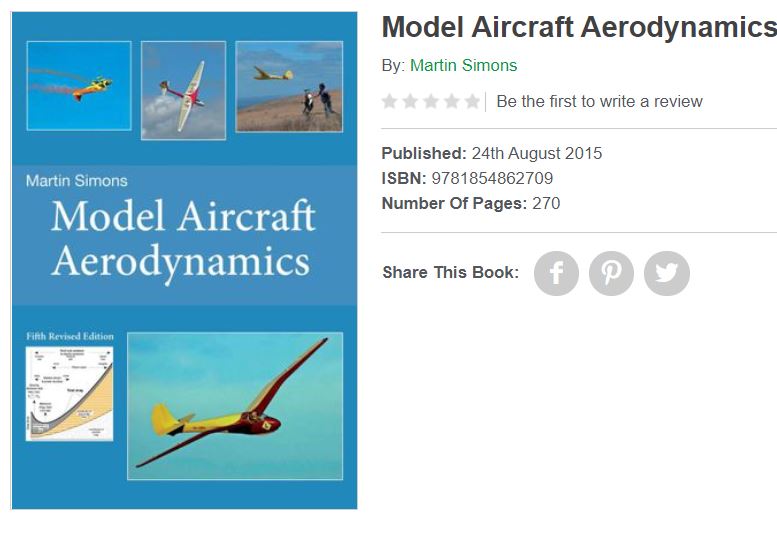
To check my work I even bought a book from the US ( it only took 4 .5 weeks to arrive ) titled Model Aircraft Aerodynamics by Martin Simonds and Im having a blast reading it and comparing his knowledge with my design, so far so good.
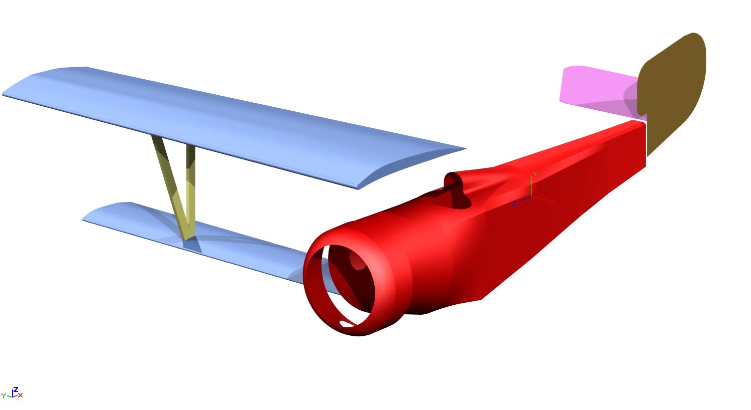
Okay so heres a simple render of the Nieuport 17 that I did this morning. Theres nothing really special to the 3D render, but it does serve as the the basis for getting the drawing correctly scaled before committing to a design.
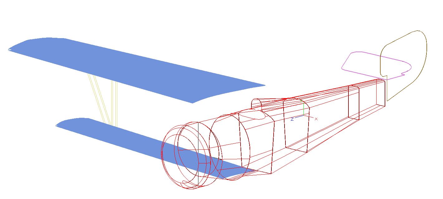
And heres some of the process steps and renders for background information, starting with a wire diagram of the key parts. Now I only drew one half of the drawing but after reviewing my that half it was not clearly comprehendible what I was was looking at at so I added the 2nd/other half of the fuselage just for clarity.
So heres the references that I used to get to this point in time.
Nieuport 17,pdf
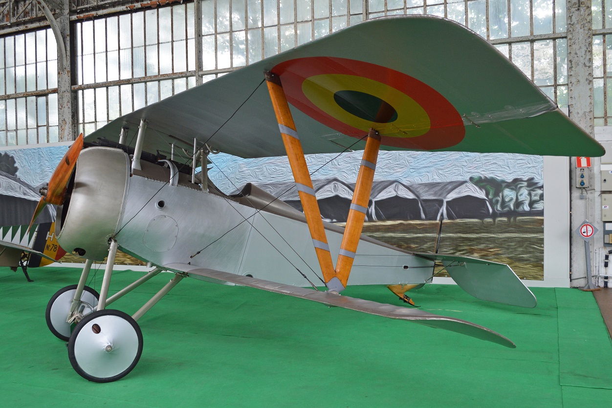
Heres a reference image that Ive used for the Nieuport cad design.
And finally here an image that I layed side to side the Nieuport 17.pdf inside my CAD program for further reference.
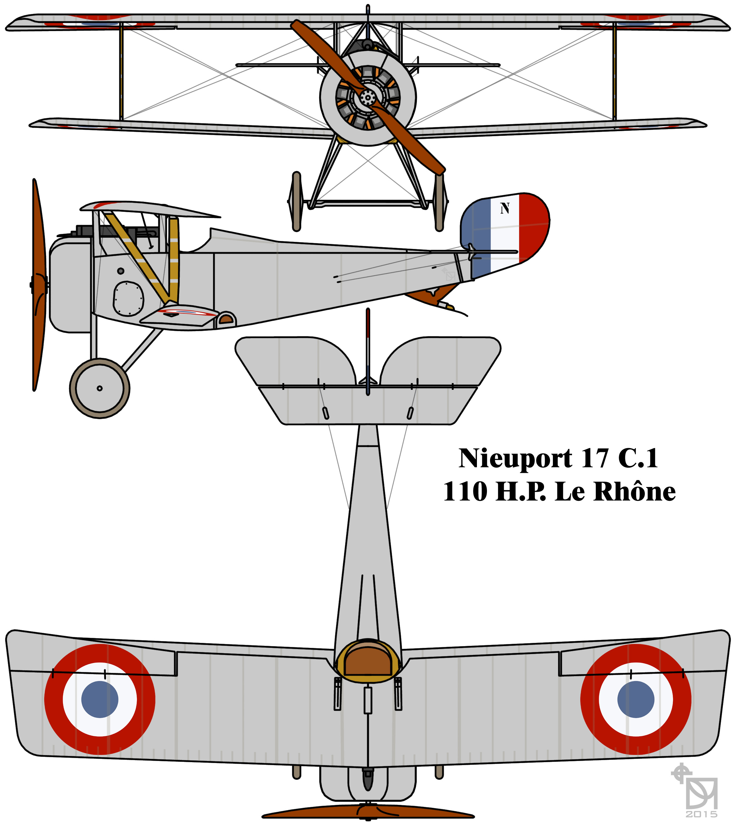
I just scaled this image above to the imported pdf file and adjusted the XY scale accordingly. The benefit here is that while the pdf and this image share many similarities that are not an exact match, but they share enough like to like detail that makes designing a much simpler approach.
So my general approach to designing rc models is:
1. If the plans have a scale use it for now, models can be re-scaled later. Insert the reference pdf into your cad program.
2. Draw the profile of the fuselage/wings using splines, curves, lines or polylines ( or whatever tool youve got )
3. An alternative is to draw the formers as a starting point.
4. Using lofting tools and or simple extrudes to create the overall structure
5, Check your design against a suitable image thats not necessarily part of the reference pdf. maybe a wikipedia source image, then compare.
6. Happy camper then move ahead, otherwise refine your drawing techniques ( splines, curves, lines or polylines etc )
7. Got a suitable cad drawing thats comparable to the image ( Nieuport_17_C.1_French_First_World_War_single_seat_fighter_colourized_drawing.jpg ), then great move ahead.
8. Now hide all your lofts, solids, surfaces and extrudes etc that form part of the rendered view and just leave the basics like splines, curves, lines or polylines etc.
9. Example: Say in the case of an open spline ( closed splines dont work here ) that is used as the basis of part of the fuselage, what you need is to get the total length of that spline/polyline and to lay it flat on your workspace, this way your creating a 2D flat drawing. This 2D drawing is then used as the basis of cutting the foam.
10. Youve gotta lay out these 2D reference lines as per 9 above in the same manner that you created them in a 3D space. By that I mean by using the same spacing apart from one spline/polyline to the next spline/polyline etc, maintaining the correct spacing until youve laid out all the 2D profiles for the fuselage/wing ect.
More to come...
To check my work I even bought a book from the US ( it only took 4 .5 weeks to arrive ) titled Model Aircraft Aerodynamics by Martin Simonds and Im having a blast reading it and comparing his knowledge with my design, so far so good.

Okay so heres a simple render of the Nieuport 17 that I did this morning. Theres nothing really special to the 3D render, but it does serve as the the basis for getting the drawing correctly scaled before committing to a design.

And heres some of the process steps and renders for background information, starting with a wire diagram of the key parts. Now I only drew one half of the drawing but after reviewing my that half it was not clearly comprehendible what I was was looking at at so I added the 2nd/other half of the fuselage just for clarity.

So heres the references that I used to get to this point in time.
Nieuport 17,pdf
Heres a reference image that Ive used for the Nieuport cad design.

And finally here an image that I layed side to side the Nieuport 17.pdf inside my CAD program for further reference.

I just scaled this image above to the imported pdf file and adjusted the XY scale accordingly. The benefit here is that while the pdf and this image share many similarities that are not an exact match, but they share enough like to like detail that makes designing a much simpler approach.
So my general approach to designing rc models is:
1. If the plans have a scale use it for now, models can be re-scaled later. Insert the reference pdf into your cad program.
2. Draw the profile of the fuselage/wings using splines, curves, lines or polylines ( or whatever tool youve got )
3. An alternative is to draw the formers as a starting point.
4. Using lofting tools and or simple extrudes to create the overall structure
5, Check your design against a suitable image thats not necessarily part of the reference pdf. maybe a wikipedia source image, then compare.
6. Happy camper then move ahead, otherwise refine your drawing techniques ( splines, curves, lines or polylines etc )
7. Got a suitable cad drawing thats comparable to the image ( Nieuport_17_C.1_French_First_World_War_single_seat_fighter_colourized_drawing.jpg ), then great move ahead.
8. Now hide all your lofts, solids, surfaces and extrudes etc that form part of the rendered view and just leave the basics like splines, curves, lines or polylines etc.
9. Example: Say in the case of an open spline ( closed splines dont work here ) that is used as the basis of part of the fuselage, what you need is to get the total length of that spline/polyline and to lay it flat on your workspace, this way your creating a 2D flat drawing. This 2D drawing is then used as the basis of cutting the foam.
10. Youve gotta lay out these 2D reference lines as per 9 above in the same manner that you created them in a 3D space. By that I mean by using the same spacing apart from one spline/polyline to the next spline/polyline etc, maintaining the correct spacing until youve laid out all the 2D profiles for the fuselage/wing ect.
More to come...


