Experimental Airlines Photon build (4/5th scale)

DuncanM23

Member
This is my second ever build, and the first without plans. It's also my first build thread!
(The first build was a mini scout using the FT plans but tape covered (fake) depron because I'm in the UK and our foamboard is heavy!)
I wanted to build the Photon mainly because the folding wings mean that you can get a large plane in the air, but with easy transport to/from the field. The videos have a 60" wingspan and a 45" fuselage, but I wanted to get something shorter than the 45", hence the 4/5ths scale.
The video series from EA is here:

I started a little while ago, so here's some pictures of the progress:
Taping the depron before folding the wing (this is one half of the total wing - I'm assembling them as a pair). Note how the depron curves due to the surface tension of the tape - this is really frustrating as you try to add more rows. Also, the white tape is so thin, it barely changed the colour of the depron underneath - if I'd realised that I wouldn't have done red and white colours!
PXL_20230108_113221085.jpg


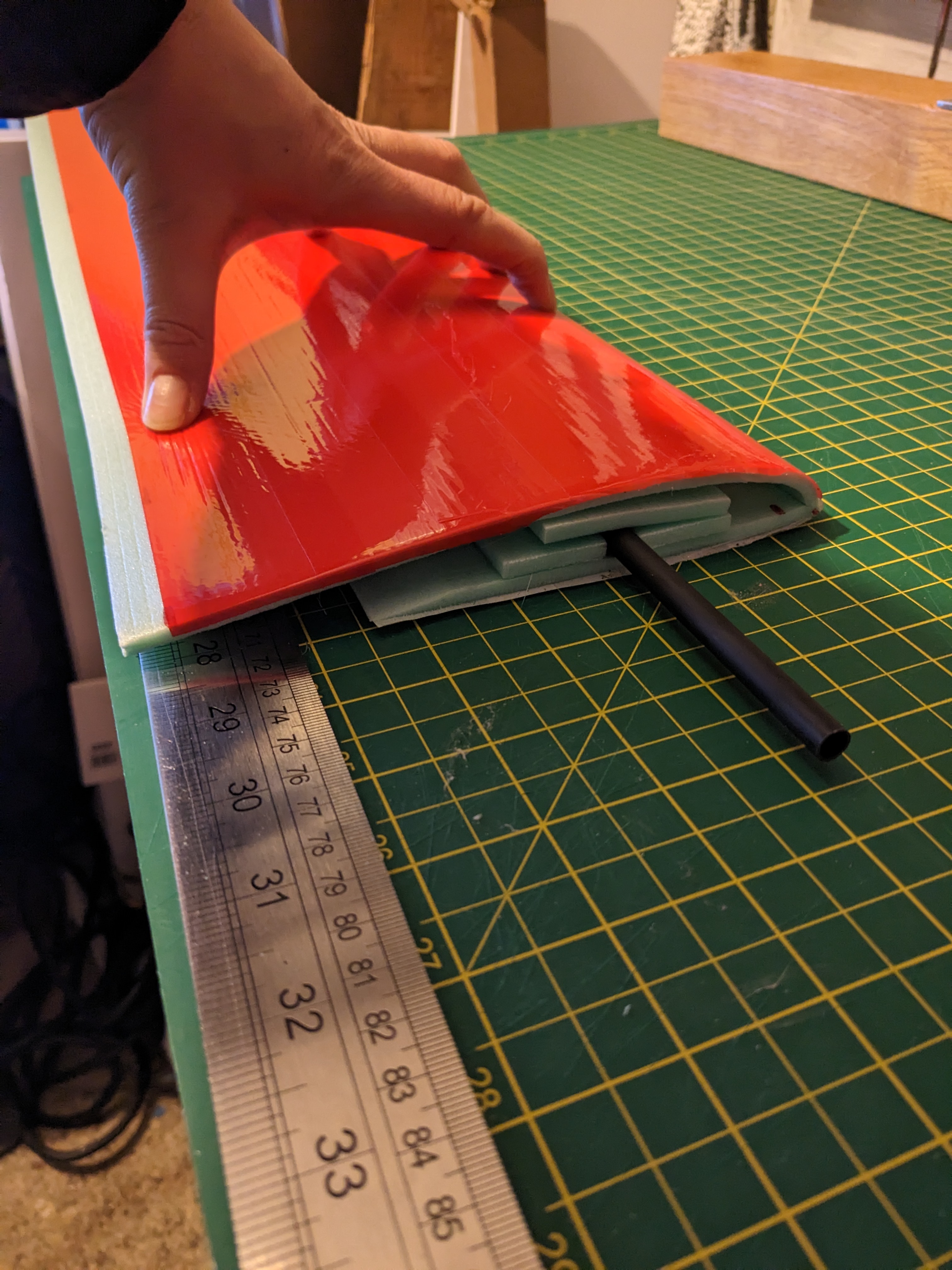
Here you can see the marks where I folded the wing, and also the formers that are glued inside the wing. You can see the carbon arrow spar - it's not glued in place - sliding it in and out of the channel is how the wing folds in half for transport, but remains rigid in flight. You can just about see how I lined up the fold with the 2-tone tape job (more about that later). The trailing edge of the bottom surface is sanded, and the top surface will glue to this with a large overlap for the ailerons
PXL_20230108_141348615.jpg

And now it looks like a wing:
PXL_20230108_141358452.jpg
 

DuncanM23

Member
To make the pair, you have to take a huge amount of care when placing the second set of formers, so that they match up and the arrow will slide through them:
PXL_20230115_143723575.jpg

I thought that this looked pretty good and everything was straight and well aligned:
PXL_20230115_143643803.jpg

But when I'd stuck them down, I discovered that one of them has a slightly fatter nose than the other, meaning they are very slightly different chord lengths as well. I'm hoping this won't matter and will just affect the aesthetics (and I may cover up the join). You can also see that my 2-tone bit is slightly off - I'm not sure if this is due to the leading edge difference or the tape, it's probably a bit of both.
PXL_20230205_130341629.jpg

PXL_20230205_130418079.jpg

If I was going to do another set of wings, I would tape the top surface of both wings together, and use a big piece of angle iron to bend them both at the same time. And I'd practise doing that until I got it all sorted and everything was neat. Also, I'd use gorilla glue to give myself time to line everything up just so - this was all done using hot glue so I had to rush it and couldn't really reposition things.
 

DuncanM23

Member
The somewhat wonky leading edge colours:
PXL_20230205_130435409.jpg

And this shows the difference in leading edge shapes:
PXL_20230205_130609810.jpg

I dithered for a while, but decided that I would carry on and see if it would fly like this - I won't lose anything by finishing it, and I can always make another set of wings. Experimental by name, experimental by nature. :)
So I started on the fuselage.
The 45" one is made of a 15" section and a 30" section, but I was thinking I might get away with a 30" one and no join so I made up a tube:
PXL_20230219_163101526.jpg

I taped it first, then folded it, and then put a second layer of taped depron inside at the join (tape side inward, gorilla glue on the depron). Trying to get the inner bit down the tube was a real pain, and I wouldn't have been able to do this section with hot glue. You can see from the little bit sticking out by the blue clamp that I didn't get it all the way in, but I was able to add a reinforcement at the other end after. It was really handy that it fitted so snugly over the steel box section, but it was a real pain to get the steel out after the glue had dried (I left it for a couple of days to ensure it was dry and would stay square).
 

DuncanM23

Member
After much thought, I decided I wanted the extra length so that the proportions were right, so I made a 6" nose box. This is going to cause me some issues, because it means that the join for the nose part is going to be right where I want the hatch to be (the original has this junction right under the wing). I have a cunning plan for that, but we'll have to wait and see how cunning it really is!
PXL_20230225_161249997.jpg

I also finished off the ailerons with the EA "kissing tape technique - they move pretty well and have a really sharp training edge:
PXL_20230225_160630695.jpg

PXL_20230225_160601782.jpg

I made a motor mount from some 1.2mm steel I had lying around, but I'm not totally happy with the attachment - I may try to weld some captive nuts onto the back so it's easy t take the motor on and off:
PXL_20230226_170136428.jpg

And I cut and glued the nose section to bring it down to the same size as the back of the motor mount. This is it just slotted into place on the main fuse (using gift cards cut and glued inside the main fuse - not yet glued into the nose):
PXL_20230302_194401969.jpg

It needs some tidying up and some more tape, but I'm going to wait until I've sorted out the motor mount and the hatch before I try to make it look tidy.
Finally, a shot of it all just balancing together. There's a lot of work needed (motor mount, tail to be built, all servos mounting, wing tie-downs, hatch), but it's finally starting to look like it might be an aeroplane!
PXL_20230302_194613960.jpg
 

FoamyDM

Building Fool-Flying Noob
Moderator
Nice work so far! Are you adding camera, FPV, gyros, or will it be more basic?
 

Piotrsko

Master member
Basd on my experiments, the wing difference means it stalls towards the thin wing and wont loop straight. Bit of trim and you'll never notice
 

Draftman1

Active member
I found it difficult to make each wing section exactly the same,

Like Piotrsko said, A little trim and you will never notice.
 

DuncanM23

Member
It's going to be no frills. Part of the joy of it is that it's so aero it should be able to fly for a long time on a 2200.
I made some progress today, in a 2 steps forward one back way.
I got hold of some 2mm x 20mm aluminium strip, so I made these as front end supports and wing tie downs:
PXL_20230303_151124241.jpg

They are overkill for the tie downs, but they should hopefully mean that the hatch is nice and wide and doesn't weaken the front end. I fitted them and gorilla glued them in place like so:
PXL_20230303_152843011.jpg

Then I moved onto the motor mount. I went to the hardware store, got some nice cap head bolts and nuts, and after fiddling with the holes got everything mounted just so. Then I tack welded the nuts to the mount. Talk about a giant balls up. I managed to weld the bolts into the nuts, so I ended up having to cut them all off (except the one that sheared that you can see in the picture)!
PXL_20230303_160931179.MP.jpg

Back to square one, after lots of effort and swearing. I guess at least it proved I can still weld, though they aren't pretty. Also, I thought I had run out of gas on my welder - turns out I was using the flow meter wrong, so I did have gas, I just didn't use it! I'm not going to try that again though, I'm just gonna bolt them on with nuts on the back (and spring washers to stop vibration) and then stick the motor mount on the outside of the nose. If I need to remove the motor for some reason, the whole thing will have to come off.
If I get a chance this evening/weekend , it will be the hatch and nose mounting, and after that I'll have to build the tail feathers. I'm not looking forward to trying to make them flat, which is why I've left them to last. I also have to add the ailerons - again, cutting into the wings is somewhat daunting, so I've put it off, but I can't for much longer.
 

DuncanM23

Member
While I was thinking about whether todo the motor mount again, or to use the Flite Test style and just glue and tape some ply on the front, I got going on the stabilisers. I wasn't quite sure of the angles/sizes, so I made them out of cardboard first:
PXL_20230304_123745251.jpg

I figured that looked OK, so I taped up some depron (I had already got a red side from the nose, I just needed to do the white side), and cut the same shapes as the cardboard. I think it looks pretty good. I want to put a skewer in as a spar, and also on the leading edges so that they don't just get wrecked in transit, so they aren't finished, and they don't have moving control surfaces, but it's great seeing how it all looks. :)
PXL_20230304_125427931.jpg

That's just with everything placed there (and a strategically placed bottle of glue stopping everything falling off), but it makes me want to keep working on it. Hopefully more progress soon...
 

Piotrsko

Master member
Fwiw, the tail surfaces don't look big enough for the wing. I favor 10% of wing area to be dead stable. They are far enough back
 

DuncanM23

Member
The video has a 15" wide and 6" long horizontal stab, mine is 12" and 5" (though it's actually a bit longer because he's measuring from a point, and I cut mine square at the front). The vertical fin, his is 6" tall, with 6" chord at the bottom, and 4" at the top. Mine's 5.5" with 5.5" and 3.5" chords. So it's scaled approximately right - if it doesn't have the authority then I will have to make a bigger set.
 

DuncanM23

Member
I figured I'd finish them anyway.
So I added a barbeque skewer as a spar for the horizontal stab, and as leading edges for both of them, and cut and installed control surfaces and feathered the trailing edges. Aside from trimming a bit off the rudder to allow elevator up, and wrapping the exposed top/end edges of foam, they are basically done. I used Uhu Por for attaching the skewers because I didn't want the foaming of the gorilla glue - I think that was the right call, but I may have covered up the spar before it was totally dry - I wonder if that means it's going to take forever. Pictures:
PXL_20230304_175918360.jpg

PXL_20230304_175910699.jpg

And then balanced n the fuse:
PXL_20230304_180030813.jpg

PXL_20230304_180002313.jpg

And bonus content - I cut the rest of the hatch into the front section (but I've not glued that yet):
PXL_20230304_180816862.jpg

The aluminium rails are going to make it proper sturdy, but I've still not decided if the motor goes in the fuse or outside, and on the steel mount, or on (as yet unmade) plywood. I won't make as much progress tomorrow as I'll be flying my Wot4 in the morning, but I might get some in when the rest of my family is binging Emily in Paris! :)
 

DuncanM23

Member
A little progress in the last couple of days. Firstly, I updated the motor mount so that the motor could attach better, and there was more space for the cables to pass past it. Then I stuck the tail on during my lunch hour. I used the EA technique of a gift card bent to 90 degrees and stuck through the fuse and the horizontal stab, and alongside the vertical stab. That seemed to work, so I stuck it all together with tape, but as expected the vertical stab was a bit wobbly, so I hot glued the join as well (and I also hot glued the front of the horiz stab where it meets the fuse). It was a slightly rushed job, and when I look at it now, while I think it lines up nose-tail, I think the vertical stab is a few degrees off the vertical. Hopefully that makes very little difference.
236124

I hot glued another id card inside the fuse where the motor mount will go, so that if it comes off it won't destroy the foam and it can be re-attached. Then yesterday evening, I attached the motor (this time sturdily bolted to the mount). Sadly I didn't take any photos of this bit before stuffing it into the plane! I took a bit more care with this one, and made sure it lined up as straight as I could get it (the side of the fuse is lined up along one of the building board lines, but the picture looks strange because the nose taper is inconsistent)
236125

And finally here it is with the spinner and folding prop attached. I need to attach the nose to the fuse, add the hatch, and then install all the servos, and then hopefully it will be ready - probably another week or so.
236126
 
Last edited:

DuncanM23

Member
I stuck the nose on.
236143

And after leaving it overnight to cure, and then peeling the fuse from the board and the clamps and the stabilizing steel, I couldn't resist and attached the wings using the rubber bands and took it outside:
236144

The only physical bits it needs now are end caps and a hatch. The rest is installing the electrics.
If it stays this windy I won't be able to fly this weekend, so maybe I can get a good start on them.
 

DuncanM23

Member
More progress yesterday - made the hatch, taped the nose up properly, attached 2 rubber bands each side and taped them in:
236181

236182

I failed to make my tiny magnets work - it stays closed due to friction but I can't fly it like that. If I can't get the magnets to work by the time I am ready to fly, I'll just tape it down.
I also chopped holes into my wings for aileron servos. That was somewhat nerve wracking - I was really aware that mess it up and I could punch a big hole in my wing!
236183
 

DuncanM23

Member
More progress today.
I managed to get my servos centred (not yet got a servo tester, had to bind my receiver which took a while as I'd not used a V8 receiver before), added the arms and then fed the cables through the wing. It took ages to get them through - the channel is really tight, and there was hot glue in the way in a couple of spots.
236185

236186

I then made the wing tips out of coroplast (after checking if I could glue it effectively to the depron) , cut the hole, taped the outside and mounted them. I also taped the wing join - it's taped on the bottom surface and then the tape is wrapped around the top surface for each wing independently, so you can push the spar (carbon arrow shaft) through from one end, and when it passes the middle the whole thing folds. :)
236187

236188

That took quite a while, so I didn't get a chance to make the control horns or attach the servos for the elevator/rudder. That's pretty much all there is to do on it, so I'll have to do that next time.
Oh yeah, while I had the receiver bound, I plugged the motor into the speedo and checked that the motor span the right way. So I got to take a picture of the motor inside the front:
236189

And obviously I had to take a picture of it with wings with wingtips (couldn't be bothered fighting with the rubber bands just for the picture):
236190

So near, yet so far.
Left to do:
1. Properly mount servos and control horns.
2. Mount speedo and receiver.
3. CG testing and battery placement.
4. Make the speedo brake when not under throttle.
 

DuncanM23

Member
Loads of progress today. I installed the control horns for the ailerons yesterday, but I failed to cut the control rod quite right, so it wasn't going to work properly. Today I gave up on the double Z bend and used the linkage stoppers. Then I installed the control horns and servos for the elevator and rudder.
PXL_20230325_153411650.jpg

So I stuck the prop back on, attached the wings and went outside to take a picture or 2:
PXL_20230325_152434945.jpg

It weighs about 580g without a battery or receiver.
The only issue is that it's basically perfectly balanced without battery or receiver. The hatch is in front of the wing - I think I'm gonna need to make another small hatch behind the wing to put the receiver back there. Then I can put the battery under the front edge of the wing through the front hatch, and hopefully I don't need to add tail weight to make it balance (depends on the size of the battery).
Question - if I put the receiver a long way away from the speed controller, can I use an extender? I'm just concerned about whether that would be bad for voltage drop?
 

Merv

Site Moderator
Staff member
...Question - if I put the receiver a long way away from the speed controller, can I use an extender? ...
Yes, I've done it many times.
There is a debate on which side to add the wires, some say on the motor side, other say on the battery side. I'm not sure it matters. I've always added wire to the battery side, 2 wires are just easier than 3.

BTW, great looking plane!
 

DuncanM23

Member
I did some experimenting with where I can put the battery and receiver to make it balance. If I put them here, it balances round about on the spar (maybe slightly forward).
View attachment 236505
That's about as far back as I can get this battery with this hatch. I'm considering making some sort of tray so the battery can be velcroed to that, and then the tray can velcro to the fuse. That way I can get the battery further down inside the plane and still get it in and out! I'm not sure the hatch is big enough to do that and get the tray and the battery in at the same time, (and there's not really enough space for a sliding tray). I had similar battery placement issues with the last foamboard -> depron build I did (flite test mini scout) - think I need to learn my lesson and make the tail from something a bit more heavy duty next time!