
OutcastZeroOne
Fly, yes... Land, no
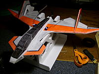
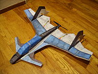
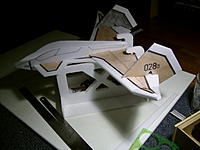
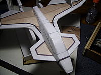
Hey all, thought I would share my F/A-241 Shrike design that I've been working on for the past few months. Some of you may recognize it from RCG or www.parkjets.com. If interested you can read the devolpment from the original thread on RCG (http://www.rcgroups.com/forums/showthread.php?t=1704960). Sorry in advance about all the pictures.
F/A-241 Shrike (thanks to Dickeroo for the name suggestion)
Supplies:
1-1.25 sheets of Readi-Board (Dollar Tree foam board, paper removed)
Parts:
Servos:
2 HXT900 Servos
Power System:
AX 1806N 2900kv motor
(these motors have similar specs:
AX 1806N 2500kv Brushless Micro Motor (19g) (this is the closest to what I am running)
C2222 Micro brushless Outrunner 2850kv (15g)
ESC:
TURNIGY Plush 12amp (2A BEC) BESC
Battery:
Rhino 460mAh 3S 11.1v 20C Lipoly Pack
to
Rhino 610mAh 3S 11.1v 20C Lipoly Pack
Prop:
TGS Sport 6x4E Precision propeller
or
GWS EP Propeller (DD-5043 125x110mm)
Wingspan: 26"
Length: 20"
Height: 6"
Around 190 grams flying weight. (with Kfm4 wing and some tape)
KFm2 or Kfm4 wing
Prebuild preparation:
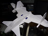
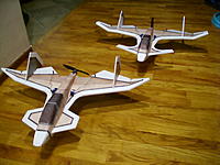
1. Decide on the airframe. There are 3 finalized versions of the aircraft (A, B, and C). There are also a number of alternate canards and tails to choose from on the craft, giving you many possibilities and ways to customize your Shrike.
F/A-241A
Original design. Has a strait leading edge wing. Lightest of all the versions and very nimble.
Full
Tiled
F/A-241B
Slightly larger wing on the "B" model. Has a "double delta" step where the tail attaches to the wing. Very good and nimble airframe.
Full
Tiled
F/A-241C

Canardless version of the air frame. Can use with the "A" or "B" main wing with a large wing root to get rid of the need for a canard. Good for areas with sudden gusty winds.
(Parts are included on both "A" and "B" model plans as optional parts)
2. Decide on a canard or no canard if going with the "C" model.
Original F/A-241A canard. Low drag decent lift.
Original F/A-241B canard. Thin, long canard. Good lift and maneuverability.
Forward swept canard. Great lift. Good for if useing a battery a little larger then the 460mah Rhino. But can be pitchy in gusty winds.
(included in plans as optional parts)
shorter but wider version of the "B" canard. Good lift and maneuverability.
(included in plans as optional parts)
Makes the airframe into the "C" model. Trades canard for a wide wing root.
(included in plans as optional parts)
3. Pick your tails. All different tail designs work equally well with very little differance in performance between them. mostly aesthetics.
Standard version. Comes with all plans.
(included in plans as optional parts)

Sweptback tail
4. All versions will use this canopy brace. Cut out of good cardboard or posterboard. Will be needed to help hold and align removable hatches.
(included in plans)
Building a Shrike:
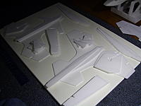
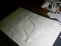
1: Cut out all your parts. Depending on if you want to make it with a Kf2 or Kf4 wing. Kf2 version will need 1 full sheet of Readi-Board, Kf4 will need slightly more.
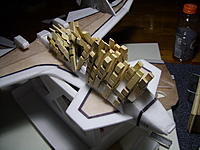
2: Glue down one side worth of Kf step parts and fuselage floor. Flip over and repeat. If you are doing a Kf2, you need only attach the second floor bracing underneath. Be sure you install your wing bracing.
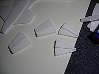
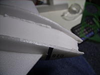
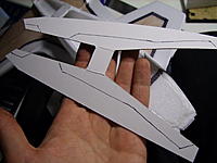
3: Assemble the winglets, gluing the Kf steps to the main winglet body.
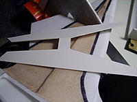
4: Attaching the winglets. The winglets go on at an angle. Either cut or sand the edge to the require angle and glue the winglets on in place. Use the supplied angle guide to get the correct angle. (22°)

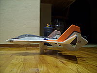
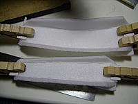
5: Its a good idea to round the leading edges of the wings. I made a simple tool using some 1/2" PVC pipe and sand paper. At this point its a good idea to start some basics of the paint. This model is a bit difficult to fully color once fully assembled. I went with a basic "VF-1A" paint scheme, going back to my Macross roots

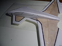
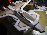
6: Preping the Fuselage sides. On the plans I say to use a pin to mark where the canopy, and ESC cover are to be cut out from. Once the pin locations are punched into the foam, its a good idea to draw the lins for the canopy and ESC cover before gluing the fuselage sides on. Do not cut out the parts yet. just get them glued on to the main wing.

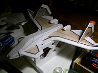
7: At this point you can glue the tails on.
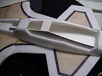
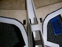
8: Close up the fuselage. You will need to notch the front of the fuselage down so that the top piece will lay flush between the sides of the fuselage at the nose. I start at the back and work my way forward taping the sides of the fuselage shut against the top piece. You may also notice that as the fuselage is closed, it will bend the front of the fuselage down, giving the canards a slight negative incidence to the main wing. This is fine.
For those who do not know what incidence is, it is the angle two control surfaces are to each other. Meaning if you draw a line strait off the main wing, and a line off the canard you will see they do not line up, but cross each other at a different angle.
9: Do the same to attach the under belly piece on.
10: When the glue has fully set, hit the foam quickly with a heat gun. This will help set the foam in the shape of the fuselage. You will now be cutting out the canopy and ESC cover. If you don't heat the foam, it will spring out and be hard to line back up to make use of the cut parts as removable covers.

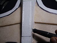
11: Next we get the canopy brace ready. This part is to be made from good, stiff cardboard.
First place it into the fuselage and trace the canopy line. This will help you so that you don't use too much glue.
Be sure to secure the brace in place as the glue sets.
12: Glue some small tabs of cardboard to the front and back of the canopy and ESC covers you cut out. The cardboard tabs will allow you to easily remove or install the covers when needed. You will simply need to bend the foam slightly to secure, or remove the cover. you want about 1/8" to 1/4" (3mm - 6mm) of tab hanging off the edge of the foam.
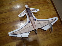
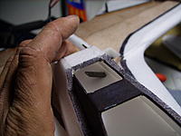
13: Glue on the motor mount and your favorite type of control horns. I cut the control horns in about 3/4" in from the edge of the control surface. The motor mount I made is simply a round piece of plastic I cut out with a hole saw, and glued onto the back of the fuselage. Be sure that when you glue the motor mount on that you have it inline with the canards angle of incidence.

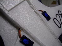
14: Cut out the servo areas. I go about 1/4" from the Kf step leading edge, and about 1/4" from the fuselage body. You can go flush against the fuse if you wish. My servo cut out template limits me here for useing my hot wire knife.

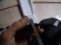
Next I cut a small opening to run the servo wires into the fuselage. I happen to have a small file that is almost the exact same size as the servo plug.
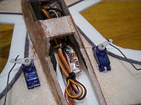
15: Install servos, and run wires inside.
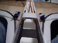
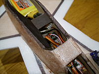
16: Cut out a small opening to run the motor wires inside.
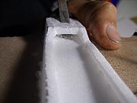
Install motor and run in your wires
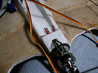
17: Install the rest of your electronics, and string up your servos.
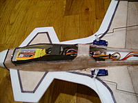
18: Finish your paint job and get it ready to fly. CG should be between the front of the Kf step and front of servos.
F/A-241 Shrike (thanks to Dickeroo for the name suggestion)
Supplies:
1-1.25 sheets of Readi-Board (Dollar Tree foam board, paper removed)
Parts:
Servos:
2 HXT900 Servos
Power System:
AX 1806N 2900kv motor
(these motors have similar specs:
AX 1806N 2500kv Brushless Micro Motor (19g) (this is the closest to what I am running)
C2222 Micro brushless Outrunner 2850kv (15g)
ESC:
TURNIGY Plush 12amp (2A BEC) BESC
Battery:
Rhino 460mAh 3S 11.1v 20C Lipoly Pack
to
Rhino 610mAh 3S 11.1v 20C Lipoly Pack
Prop:
TGS Sport 6x4E Precision propeller
or
GWS EP Propeller (DD-5043 125x110mm)
Wingspan: 26"
Length: 20"
Height: 6"
Around 190 grams flying weight. (with Kfm4 wing and some tape)
KFm2 or Kfm4 wing
Prebuild preparation:
1. Decide on the airframe. There are 3 finalized versions of the aircraft (A, B, and C). There are also a number of alternate canards and tails to choose from on the craft, giving you many possibilities and ways to customize your Shrike.
F/A-241A
Original design. Has a strait leading edge wing. Lightest of all the versions and very nimble.
Full
Tiled
F/A-241B
Slightly larger wing on the "B" model. Has a "double delta" step where the tail attaches to the wing. Very good and nimble airframe.
Full
Tiled
F/A-241C
Canardless version of the air frame. Can use with the "A" or "B" main wing with a large wing root to get rid of the need for a canard. Good for areas with sudden gusty winds.
(Parts are included on both "A" and "B" model plans as optional parts)
2. Decide on a canard or no canard if going with the "C" model.
Original F/A-241A canard. Low drag decent lift.
Original F/A-241B canard. Thin, long canard. Good lift and maneuverability.
Forward swept canard. Great lift. Good for if useing a battery a little larger then the 460mah Rhino. But can be pitchy in gusty winds.
(included in plans as optional parts)
shorter but wider version of the "B" canard. Good lift and maneuverability.
(included in plans as optional parts)
Makes the airframe into the "C" model. Trades canard for a wide wing root.
(included in plans as optional parts)
3. Pick your tails. All different tail designs work equally well with very little differance in performance between them. mostly aesthetics.
Standard version. Comes with all plans.
(included in plans as optional parts)
Sweptback tail
4. All versions will use this canopy brace. Cut out of good cardboard or posterboard. Will be needed to help hold and align removable hatches.
(included in plans)
Building a Shrike:
1: Cut out all your parts. Depending on if you want to make it with a Kf2 or Kf4 wing. Kf2 version will need 1 full sheet of Readi-Board, Kf4 will need slightly more.
2: Glue down one side worth of Kf step parts and fuselage floor. Flip over and repeat. If you are doing a Kf2, you need only attach the second floor bracing underneath. Be sure you install your wing bracing.
3: Assemble the winglets, gluing the Kf steps to the main winglet body.
4: Attaching the winglets. The winglets go on at an angle. Either cut or sand the edge to the require angle and glue the winglets on in place. Use the supplied angle guide to get the correct angle. (22°)
5: Its a good idea to round the leading edges of the wings. I made a simple tool using some 1/2" PVC pipe and sand paper. At this point its a good idea to start some basics of the paint. This model is a bit difficult to fully color once fully assembled. I went with a basic "VF-1A" paint scheme, going back to my Macross roots
6: Preping the Fuselage sides. On the plans I say to use a pin to mark where the canopy, and ESC cover are to be cut out from. Once the pin locations are punched into the foam, its a good idea to draw the lins for the canopy and ESC cover before gluing the fuselage sides on. Do not cut out the parts yet. just get them glued on to the main wing.
7: At this point you can glue the tails on.
8: Close up the fuselage. You will need to notch the front of the fuselage down so that the top piece will lay flush between the sides of the fuselage at the nose. I start at the back and work my way forward taping the sides of the fuselage shut against the top piece. You may also notice that as the fuselage is closed, it will bend the front of the fuselage down, giving the canards a slight negative incidence to the main wing. This is fine.
For those who do not know what incidence is, it is the angle two control surfaces are to each other. Meaning if you draw a line strait off the main wing, and a line off the canard you will see they do not line up, but cross each other at a different angle.
9: Do the same to attach the under belly piece on.
10: When the glue has fully set, hit the foam quickly with a heat gun. This will help set the foam in the shape of the fuselage. You will now be cutting out the canopy and ESC cover. If you don't heat the foam, it will spring out and be hard to line back up to make use of the cut parts as removable covers.
11: Next we get the canopy brace ready. This part is to be made from good, stiff cardboard.
First place it into the fuselage and trace the canopy line. This will help you so that you don't use too much glue.
Be sure to secure the brace in place as the glue sets.
12: Glue some small tabs of cardboard to the front and back of the canopy and ESC covers you cut out. The cardboard tabs will allow you to easily remove or install the covers when needed. You will simply need to bend the foam slightly to secure, or remove the cover. you want about 1/8" to 1/4" (3mm - 6mm) of tab hanging off the edge of the foam.
13: Glue on the motor mount and your favorite type of control horns. I cut the control horns in about 3/4" in from the edge of the control surface. The motor mount I made is simply a round piece of plastic I cut out with a hole saw, and glued onto the back of the fuselage. Be sure that when you glue the motor mount on that you have it inline with the canards angle of incidence.
14: Cut out the servo areas. I go about 1/4" from the Kf step leading edge, and about 1/4" from the fuselage body. You can go flush against the fuse if you wish. My servo cut out template limits me here for useing my hot wire knife.
Next I cut a small opening to run the servo wires into the fuselage. I happen to have a small file that is almost the exact same size as the servo plug.
15: Install servos, and run wires inside.
16: Cut out a small opening to run the motor wires inside.
Install motor and run in your wires
17: Install the rest of your electronics, and string up your servos.
18: Finish your paint job and get it ready to fly. CG should be between the front of the Kf step and front of servos.
Attachments
Last edited: