L Edge

Master member
To get back on subject of rudderless planes, getting antsy, added a gyro to all three axis, did a quick test run in the industrial park (33 degrees) and lifted off(gyro on) and it flew about 20 ft. I pulsed the rudder (inside the EDF) and it it yawed and drop back down. Next week, 40+ degrees and I can't wait if I can wean the roll and pitch off the gyro. Soon as snow is off in park parking lot, will try flight for single EDF.

I mentioned to you the second method I was exploring was to have dual edf's using a pair of drag brakes. Solved the problems on how I should program it and just purchased 2 sets of drag brakes(making them sucks for repeatability) and hopefully, I can cut them down to use next to the ailerons. Bought 2 sets, so I can try both ways, on trailing edge and imbedded in the wings, so you could make different styles of planes use 1 or 2 EDF's. If it does, the NYGAD problems is solved.

Any flights or data info yet on your models ready to go? Hope other FT pilots are interested in your data so they understand what is going on.

To keep busy in the house, made a EZ 2 FSW plane and thought of you when I tested in the cellar. Having a real high AOA, every time when I was exploring the CG and it was aft, pull back power, it stalls beautifully and lands tail heavy, with no damage. Same as my morphing plane.


By the way, the drag brakes are from China, if you want more info or where to buy, (only a few left- 5 for right, 8 for left), PM me. I have been waiting 4 months for this shipment to come in.
 

telnar1236

Elite member
To get back on subject of rudderless planes, getting antsy, added a gyro to all three axis, did a quick test run in the industrial park (33 degrees) and lifted off(gyro on) and it flew about 20 ft. I pulsed the rudder (inside the EDF) and it it yawed and drop back down. Next week, 40+ degrees and I can't wait if I can wean the roll and pitch off the gyro. Soon as snow is off in park parking lot, will try flight for single EDF.

I mentioned to you the second method I was exploring was to have dual edf's using a pair of drag brakes. Solved the problems on how I should program it and just purchased 2 sets of drag brakes(making them sucks for repeatability) and hopefully, I can cut them down to use next to the ailerons. Bought 2 sets, so I can try both ways, on trailing edge and imbedded in the wings, so you could make different styles of planes use 1 or 2 EDF's. If it does, the NYGAD problems is solved.

Any flights or data info yet on your models ready to go? Hope other FT pilots are interested in your data so they understand what is going on.

To keep busy in the house, made a EZ 2 FSW plane and thought of you when I tested in the cellar. Having a real high AOA, every time when I was exploring the CG and it was aft, pull back power, it stalls beautifully and lands tail heavy, with no damage. Same as my morphing plane.


By the way, the drag brakes are from China, if you want more info or where to buy, (only a few left- 5 for right, 8 for left), PM me. I have been waiting 4 months for this shipment to come in.
My tailless plane designs are on hold for the moment, but I eventually want to get back into them. My investigation of wing apex flaps in this F-106 project would possibly explain some of my control issues though. The spoiler may have actually resulted in an increase in lift on that wing, therefore counteracting some of the roll due to the yaw it generates. It would explain some of the control difficulties I've been running into. But for the moment, my stable of planes is getting a bit low since I've been working on projects without wrapping them up, so I need to finish building a few things before I get too experimental again.
 

telnar1236

Elite member
The final version of the wings is finally finished.
1740274091015.png

There are a couple of things to note.
First, the gear now has a wheel with a tire. I'd be curious to know if anyone has printed PLA wheels. I have questions about how the wheel will wear against the axle and I suspect I may need to replace them with PETG wheels after a few flights. The tire is 85A durometer TPU printed with 3 walls and 50% infill. It feels like about the right level of flexible and doesn't seem to deform too much in tests where I press down on a scale with half the weight of the plane. The grip is also much better than previous TPU wheels where I used 98A durometer filament and I think the ground handling should be fine. They also didn't permanently deform when I tried pressing them against a 100 C 3D printer build plate, likely due to the higher infill, so I think they should be able to survive Florida asphalt ok.
1740274594791.png

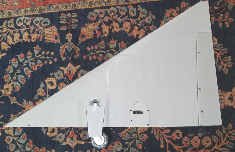
Next, the wing now bulges out by 3mm to fit the gear and gear door. The gear door couldn't quite fit flush with the gear due to the rubber bands, so that extra space means everything can fit.
1740274636928.png

Finally, the servo trays are now printed and integrated into the wing. The elevons are driven by FT99R servos which are probably far overkill for the application, but in a plane this big that might be able to hit 130 mph, and for control surfaces that size I would far rather be safe than sorry. Once I get a better sense of how fast this plane actually is (I think 130 mph is pretty optimistic and I suspect the real number will be closer to 100 mph), I may be able to go down a size or two and save about 70 or 80 grams.
Apart from the design of the wings, I decided that the wings being an inch too far back was bothering me too much, so I'm in the process of redesigning the core fuselage to move the wing forward to where it should be. Since I have to print all the other little bits, it's not really delaying the maiden flight, and even without everything modeled right, it already looks so much better. The directional stability should also be a little better, but if I'm being honest, I'm doing this for the looks.
1740275093769.png
 

Houndpup Rc

Master member
The final version of the wings is finally finished.
View attachment 248679
There are a couple of things to note.
First, the gear now has a wheel with a tire. I'd be curious to know if anyone has printed PLA wheels. I have questions about how the wheel will wear against the axle and I suspect I may need to replace them with PETG wheels after a few flights. The tire is 85A durometer TPU printed with 3 walls and 50% infill. It feels like about the right level of flexible and doesn't seem to deform too much in tests where I press down on a scale with half the weight of the plane. The grip is also much better than previous TPU wheels where I used 98A durometer filament and I think the ground handling should be fine. They also didn't permanently deform when I tried pressing them against a 100 C 3D printer build plate, likely due to the higher infill, so I think they should be able to survive Florida asphalt ok.
View attachment 248681
Next, the wing now bulges out by 3mm to fit the gear and gear door. The gear door couldn't quite fit flush with the gear due to the rubber bands, so that extra space means everything can fit.
View attachment 248682
Finally, the servo trays are now printed and integrated into the wing. The elevons are driven by FT99R servos which are probably far overkill for the application, but in a plane this big that might be able to hit 130 mph, and for control surfaces that size I would far rather be safe than sorry. Once I get a better sense of how fast this plane actually is (I think 130 mph is pretty optimistic and I suspect the real number will be closer to 100 mph), I may be able to go down a size or two and save about 70 or 80 grams.
Apart from the design of the wings, I decided that the wings being an inch too far back was bothering me too much, so I'm in the process of redesigning the core fuselage to move the wing forward to where it should be. Since I have to print all the other little bits, it's not really delaying the maiden flight, and even without everything modeled right, it already looks so much better. The directional stability should also be a little better, but if I'm being honest, I'm doing this for the looks.
View attachment 248684
WOW man! I am impressed with this!
 

telnar1236

Elite member
The nose gear is now designed. It's quite similar to what I used in the 70mm version but scaled up and improved.
1740859239778.png

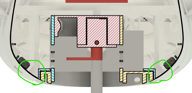
The only particularly unconventional thing about the gear is the suspension. Starting in my F-104, and in all the 3D printed planes with landing gear I've designed since then, the nose gear suspension is a 3D printed compliant mechanism. It generally seems to damp out hard landings better and gives very good ground handling. This gear bay is more complicated than previous versions (the F-104 uses 3D printed TPU blocks for example). The suspension starts out with the soft TPU wheel which essentially will not bounce (blue). It then continues in with the suspension spring (red) which works as the very thin 3D printed beams bend under load. The wave spring at the front of the gear bay (orange) helps prevent vibrations without adding much stiffness.
1740859780213.png

The gear bay is then connected to the rest of the airframe structure by a thin section of skin. This provides most of the actual suspension travel but would be too brittle without the additional shock absorption between the fuselage and the ground.
1740860082952.png
 

telnar1236

Elite member
Everything is starting to come together for what should hopefully be the final version of the plane. I've been continuing to tweak things, but finally the entire updated fuselage, wings, and tail are all assembled.
20250308_180543.jpg

One big change is that the plane now can use either an 80mm or a 90mm fan. This should give it the option for better power in flight without increasing the weight that much, or allow it to take off in a shorter distance and from surfaces other than a paved runway. This required some additional changes to the two rear sections of the fuselage and the addition of a cheater inlet. The guide vanes on either end of cheater inlet aren't designed yet, but they will make the airflow much smoother and nowhere near as bad as it currently looks like it would be. To use an 80mm fan, a second internal thrust tube will now be needed to reduce the nozzle diameter, since I needed to make it bigger to use a 90mm fan.
1741477369046.png

Another change is that the airbrake servo was moved from inside the fuselage to inside the root of the vertical stabilizer. I needed to do this since the bigger EDF didn't leave room for the old servo location, but it also means the servo will be able to be removed and replaced after the plane is assembled as opposed to the previous design, which was to be glued in place, so it's a change I'm happy with.
1741477750830.png

I haven't been in a huge hurry to wrap up this design since constant TFRs have been preventing anyone from flying pretty much every weekend so far this year. One change I'm thinking of making is trying to give the plane grass field capability. I don't think it will take all that much - probably just increasing the diameter of the nose wheels and giving the nose gear additional suspension. There aren't any paved runways near me that wouldn't be affected by the TFRs, but there are some grass fields just outside the radius I might be able to fly from. My modular jet trainer was already designed with grass takeoffs in mind and I've successfully tested it from grass, so I might also be revisiting that plane with some improvements in the near future. Unfortunately, my F-104 cannot really be modified for grass, so that one might not be flying to much for the next few years.
 

telnar1236

Elite member
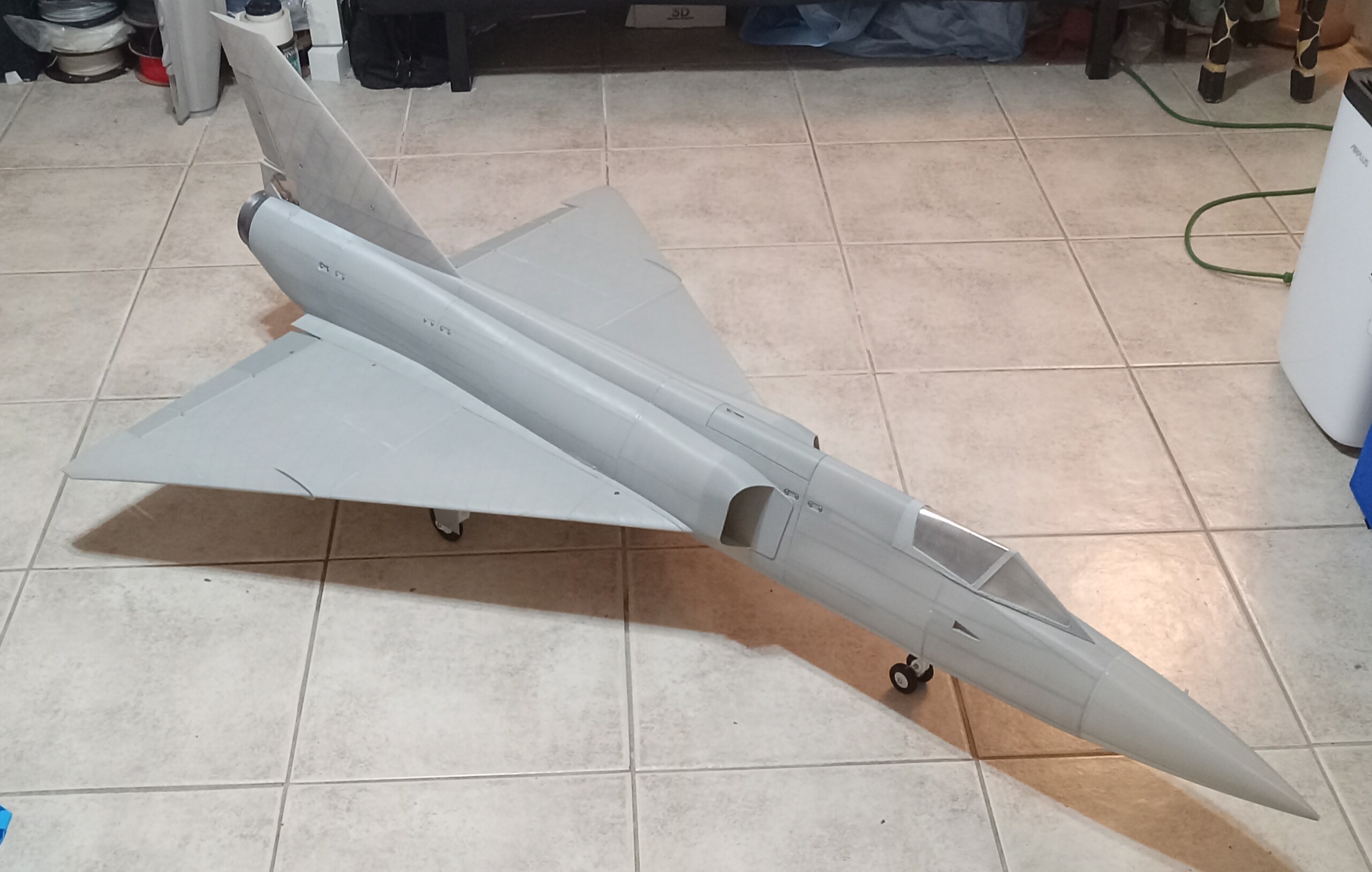
The F-106 stood on its gear for the first time today. It's getting very close to being ready to fly now. The only critical things remaining before flying are the control horns and battery tray. I also plan on having the air brakes installed since they did make landing a bit easier on the smaller version.
20250310_231801.jpg

At this point I have more than 500 hours of print time in this project and a fair few of the parts have been prototyped at least once. The total print time for someone who would want to build one of these planes would be around 350 hours. Here's a picture with some of the test pieces that I ended up needing to change for the final plane. You can see the original PLA wings and an ABS wing that I used to test acetone smoothing. Not in the picture is another ABS wing I used for destructive testing of the CA glue joints between the parts of the wing since I threw that out after the test.
20250310_232027.jpg

The gear seems strong enough, although it's a bit more wobbly than I expected. I think it's mostly just that the suspension has more travel and is a bit softer to start off with than most off the shelf designs, which was intentional. However, I may need to add another rubber band to the main gear, especially for flying off grass, depending on how the first few test flights go.
I also did decide to upgrade the nose gear suspension further like I was thinking about. The gear strut I ended up installing and which is shown in the picture uses similar suspension to the main gear. However, the nose gear suspension is more optimized to allow impacts in line with the planes forward motion since that's what I'm concerned about.
1741666035209.png

It also has the advantage of giving a bit more clearance with the gear mount when the gear is retracted. It had clearance to start with, but it was tight and if the gear had gotten bent on a bad landing, it could have been a problem.
 

telnar1236

Elite member
The airbrake system is now designed. It makes use of SLA printed gears to allow it to fit into the very narrow tail fin. It will probably take a couple of tries to get the tolerances perfect and the print dialed in, but even on the first try, the gears seem to mesh correctly and resist skipping somewhat well.
1742091085009.png

One gear fits onto the servo splines, and the other is held in place with a clamp which supports the other side of an axle made of a paper clip. This clamp also retains the pushrods in the arm on the gear which means I don't need to worry about fitting a Z bend in such a tight space.
1742091216076.png

The push rods are linked to fairly conventional control horns on the airbrakes.
1742091297592.png

This should give the airbrakes 60 degrees of travel while being a bit easier to assemble than the system on the smaller F-106.
1742091466213.png
 

Mr Man

Mr SPEED!
The airbrake system is now designed. It makes use of SLA printed gears to allow it to fit into the very narrow tail fin. It will probably take a couple of tries to get the tolerances perfect and the print dialed in, but even on the first try, the gears seem to mesh correctly and resist skipping somewhat well.
View attachment 249386
One gear fits onto the servo splines, and the other is held in place with a clamp which supports the other side of an axle made of a paper clip. This clamp also retains the pushrods in the arm on the gear which means I don't need to worry about fitting a Z bend in such a tight space.
View attachment 249387
The push rods are linked to fairly conventional control horns on the airbrakes. View attachment 249388
This should give the airbrakes 60 degrees of travel while being a bit easier to assemble than the system on the smaller F-106.
View attachment 249389
Looks good!
 

telnar1236

Elite member
The airbrake system went together remarkably easily. I need to wait until I have the receiver installed to connect the airbrakes themselves to the pushrods, but the servo and gears all seem to work quite well. Contrary to my expectations, the second version of the gears seem to work perfectly.
20250316_222710-ezgif.com-video-to-gif-converter.gif

It's a bit challenging to get good pictures of the system assembled since the retaining clip blocks the gears from most angles, but it all fits together very neatly. The assembly is very simple and doesn't require glue or a ton of fiddling around with getting everything to fit into place.
20250316_222615.jpg

20250316_222527.jpg

Probably the part I'm most proud of is the gears. They are absolutely tiny and even smaller than I expected despite knowing their size from the CAD model. The gear that goes on the servo has 3D printed splines that are only 0.1 mm in size and they interface perfectly with the splines on the servo.
1742179749353.png


If anyone is interested, I can post an STL or Fusion 360 file with the spline pattern since it seems like it could be useful for other custom servo arms, gears, or other servo hardware.
 

L Edge

Master member
The airbrake system went together remarkably easily. I need to wait until I have the receiver installed to connect the airbrakes themselves to the pushrods, but the servo and gears all seem to work quite well. Contrary to my expectations, the second version of the gears seem to work perfectly.
View attachment 249425
It's a bit challenging to get good pictures of the system assembled since the retaining clip blocks the gears from most angles, but it all fits together very neatly. The assembly is very simple and doesn't require glue or a ton of fiddling around with getting everything to fit into place. View attachment 249421
View attachment 249420
Probably the part I'm most proud of is the gears. They are absolutely tiny and even smaller than I expected despite knowing their size from the CAD model. The gear that goes on the servo has 3D printed splines that are only 0.1 mm in size and they interface perfectly with the splines on the servo.
View attachment 249423

If anyone is interested, I can post an STL or Fusion 360 file with the spline pattern since it seems like it could be useful for other custom servo arms, gears, or other servo hardware.

For your hookup, you might want to make sure that there is very little slop when you open/close the airbrakes. I found that heli parts work real well. I explored dual air rudder brakes many years ago and the slop was terrible causing yaw problems both at open/close position. Especially if they aren't closed properly in flight. Caused yaw moments in flight.

One way to resolve the slop issue is to use helicopter parts of ball joints at either end and threaded rods. Or use a ball joint and other setup as pic shows. For my servo and drag rudders, since both rudders need to be closed or at the same open angle in flight, I used ball/socket for no slop at all.
@telnar1236

Since you are in a club, find the guys who fly heli's. With crashes, comes extra spare parts, so ask some one if they have different lengths of very thin high strength light threaded rods and some ball/socket joints they will give or that you can buy. Since heli's come in all sizes, get the smallest setup you can to keep weight down. Notice the ball on the drag rudder.

If you ever get bored with planes, try helis and that will keep your heart rate up.

IMG_1503.JPG
 

telnar1236

Elite member
For your hookup, you might want to make sure that there is very little slop when you open/close the airbrakes. I found that heli parts work real well. I explored dual air rudder brakes many years ago and the slop was terrible causing yaw problems both at open/close position. Especially if they aren't closed properly in flight. Caused yaw moments in flight.

One way to resolve the slop issue is to use helicopter parts of ball joints at either end and threaded rods. Or use a ball joint and other setup as pic shows. For my servo and drag rudders, since both rudders need to be closed or at the same open angle in flight, I used ball/socket for no slop at all.
@telnar1236

Since you are in a club, find the guys who fly heli's. With crashes, comes extra spare parts, so ask some one if they have different lengths of very thin high strength light threaded rods and some ball/socket joints they will give or that you can buy. Since heli's come in all sizes, get the smallest setup you can to keep weight down. Notice the ball on the drag rudder.

If you ever get bored with planes, try helis and that will keep your heart rate up.

View attachment 249448
These airbrakes are a bit different from split rudder air brakes in that they only deflect outwards at the same time. I'm planning on using ball links for the majority of my control surfaces, but for the airbrakes there isn't really enough space. On the smaller F-106 a similar setup seemed to work without problems, so I'm hopeful that the airbrakes on the big F-106 will be ok too
 

Mr Man

Mr SPEED!
These airbrakes are a bit different from split rudder air brakes in that they only deflect outwards at the same time. I'm planning on using ball links for the majority of my control surfaces, but for the airbrakes there isn't really enough space. On the smaller F-106 a similar setup seemed to work without problems, so I'm hopeful that the airbrakes on the big F-106 will be ok too
"small"😂
 

telnar1236

Elite member
Finally had a chance to maiden the F-106. It wasn't quite ready to fly, but since this was the first weekend without a TFR in a month I jumped at the chance. The tail airbrakes weren't quite working yet and the retracts had a tendency to stick in the up position so I couldn't retract them. I also didn't get video unfortunately so that will have to wait for the next weekend without a TFR. To cut to the chase, it was a mixed bag, but I did get in two flights and the airplane shows some real promise.
1742788945228.png

The first flight was fairly short. I had too much elevator authority so the plane was very touchy, but I was able to come around and get it back on the runway. I plan to have that much elevator throw available has high rates with a lot more expo. The plane should be capable of some extreme high alpha maneuvers that way.
The second flight, I reduced elevator travel to 60% of what it originally was and the plane was much more manageable. It flew great and I was able to get it trimmed out. Unfortunately, I had not changed the battery between flights, but had reset the timer, so I ran out of battery and had to try a dead stick landing. I was too far to glide to the runway and ended up going through the very top of a tree then hitting the ground outside my view. I would guess it pancaked from the small amount of damage and it should be pretty easy to repair and have flying again soon. The nose is the big repair since it shattered on impact, and I want to make some changes too to fix the issues I had prior to the flight.
 

telnar1236

Elite member
Now that the TFRs are back, I'm using the extra time to fix a bunch more of the minor issues that were left over from the initial stage of the design process. Instead of reprinting the damaged parts of the fuselage exactly as they were, I'm taking the chance to fix some issues with minor warping as the parts cooled that I ran into and to slightly improve the printing experience. I've also fixed the main gear by giving them about 1 mm more clearance from the retract unit and making the gear doors much more rigid which means they now extend and retract more reliably.

Apart from that, I'm still working on the issue with the airbrakes sticking. For all that I'm fairly proud of the design, I think I'm going to need to replace the current design with the two bevel gears with something that is easier to adjust. The problem is that the U bends in the push rods end up binding together as they move and the whole thing locks up and won't change position.