Firefox Mig-31 twin 70mm EDF

noahangel11

Well-known member
Add the bottom fuselage sheeting starting at the front of the fuselage, lining up even with the front of the F1-F2 skin. There is some foam to remove from the skin to expose a paper flap you can glue over the edge of the joint to smooth things out a little.
 

Attachments

  • IMG_9902.jpeg
    IMG_9902.jpeg
    2.4 MB · Views: 0
  • IMG_9903.jpeg
    IMG_9903.jpeg
    2.3 MB · Views: 0

noahangel11

Well-known member
Find the 2 spline foam pieces and the 1/8” spline piece that are notched out to fit over the wing and glue them together with the ply layer in the middle to make a doubler spline. The images do not show the ply spline layer, I added that to the design at a later date.
 

Attachments

  • IMG_9904.jpeg
    IMG_9904.jpeg
    3.2 MB · Views: 0

noahangel11

Well-known member
Slide the spline onto the front of the rear wing with the notched edge facing up. See pics. When satisfied with fit and making sure it is perfectly centered on the wing center joint, glue it in place.

NOTE: The final design has more forward facing wing area, to strengthen the joint where the wing meets the fuselage. Although these pics are currently outdated, the fit of the spline is the same.
 

Attachments

  • IMG_9905.jpeg
    IMG_9905.jpeg
    2.3 MB · Views: 0
  • IMG_9906.jpeg
    IMG_9906.jpeg
    1.8 MB · Views: 0
  • IMG_9907.jpeg
    IMG_9907.jpeg
    2.1 MB · Views: 0

noahangel11

Well-known member
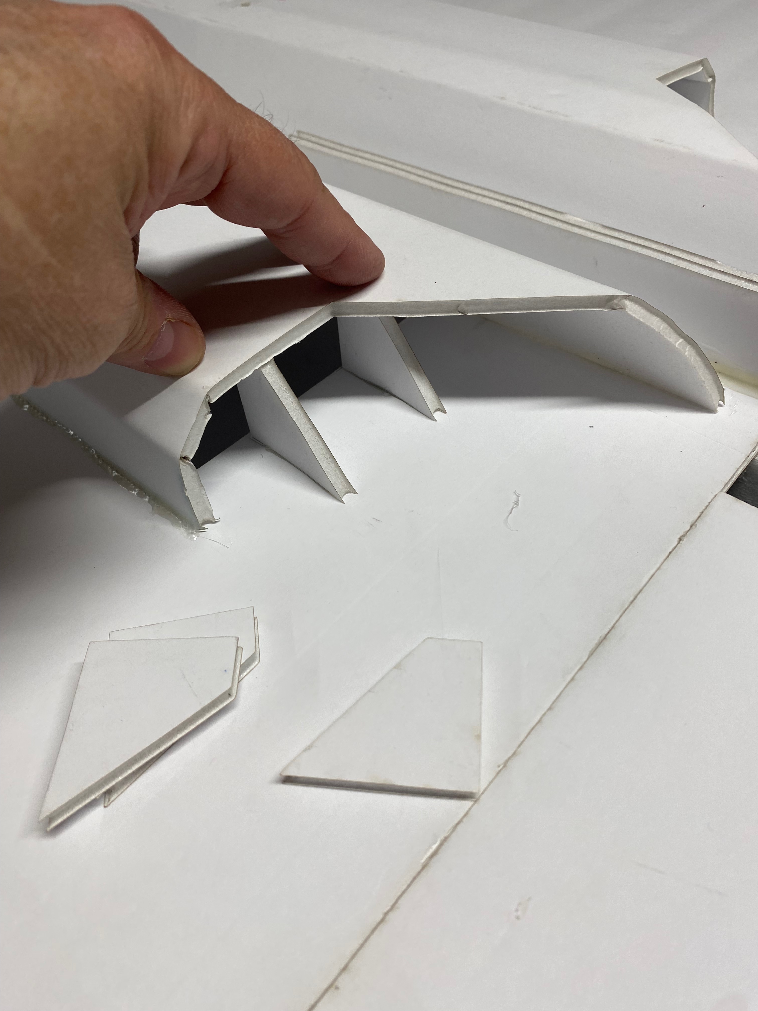
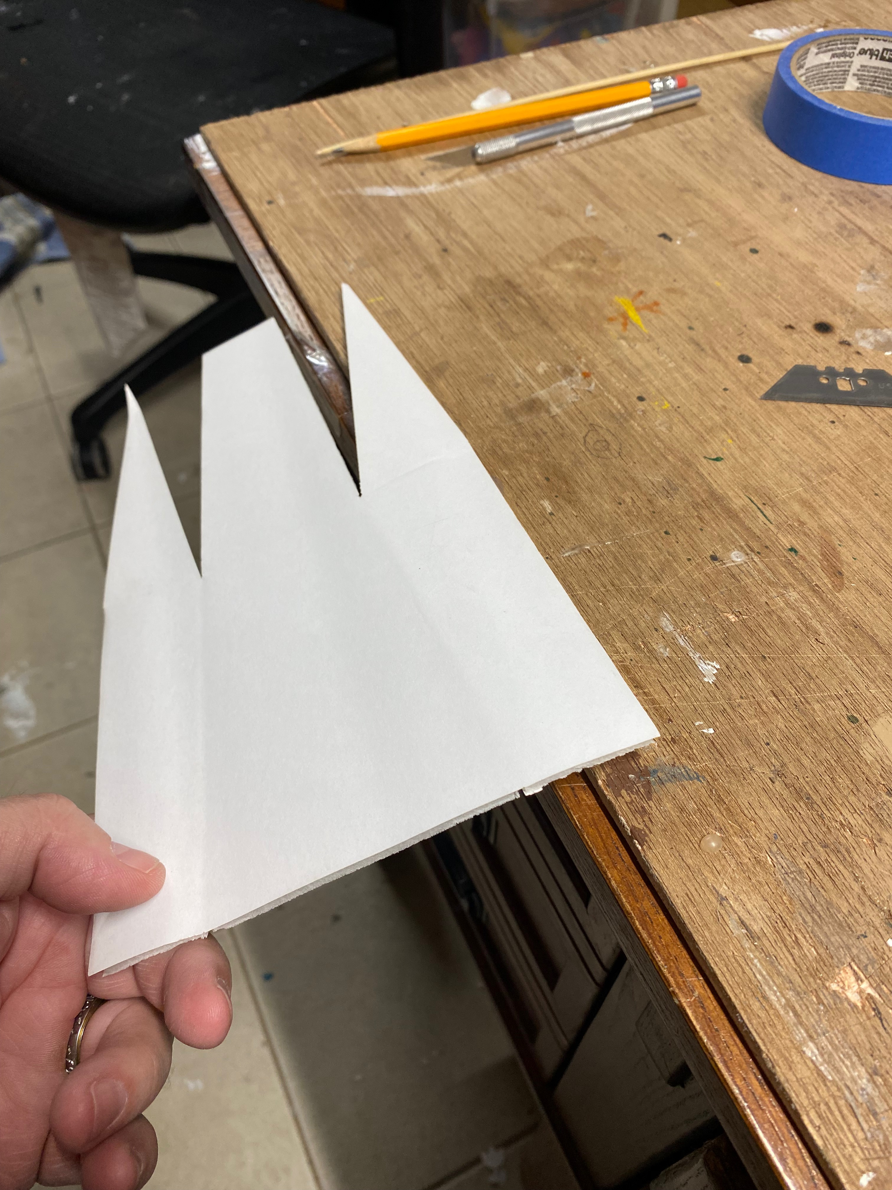
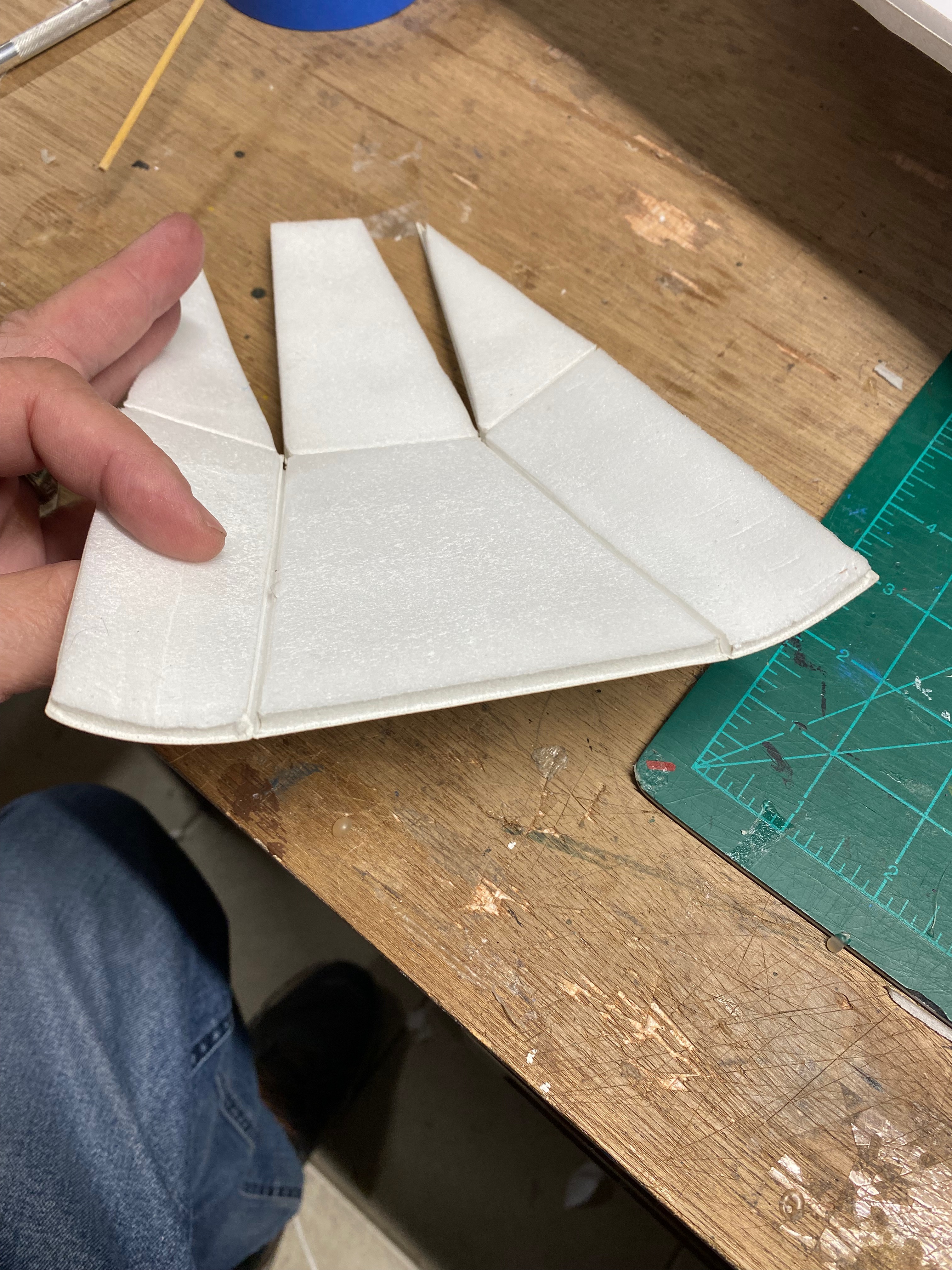
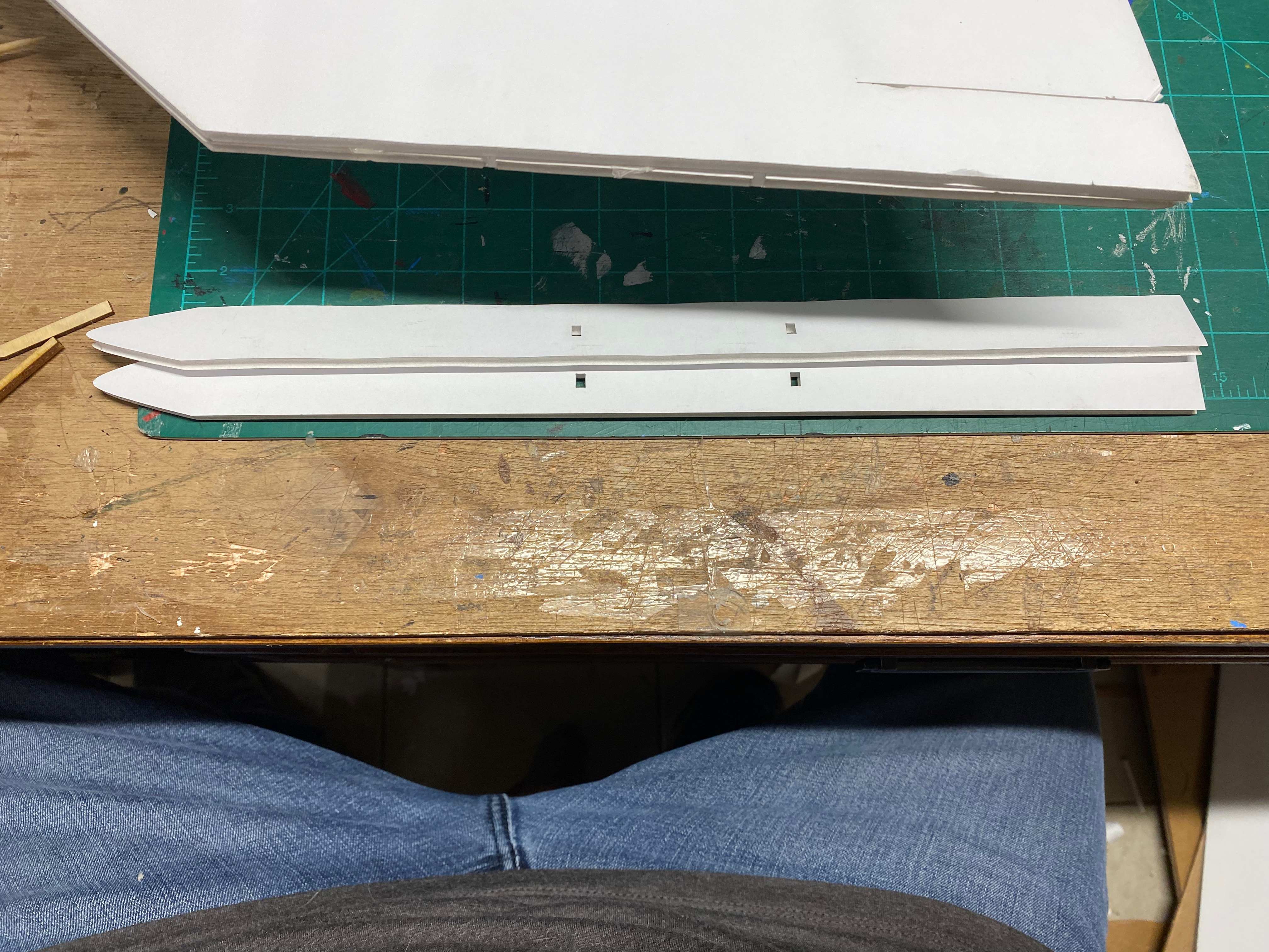
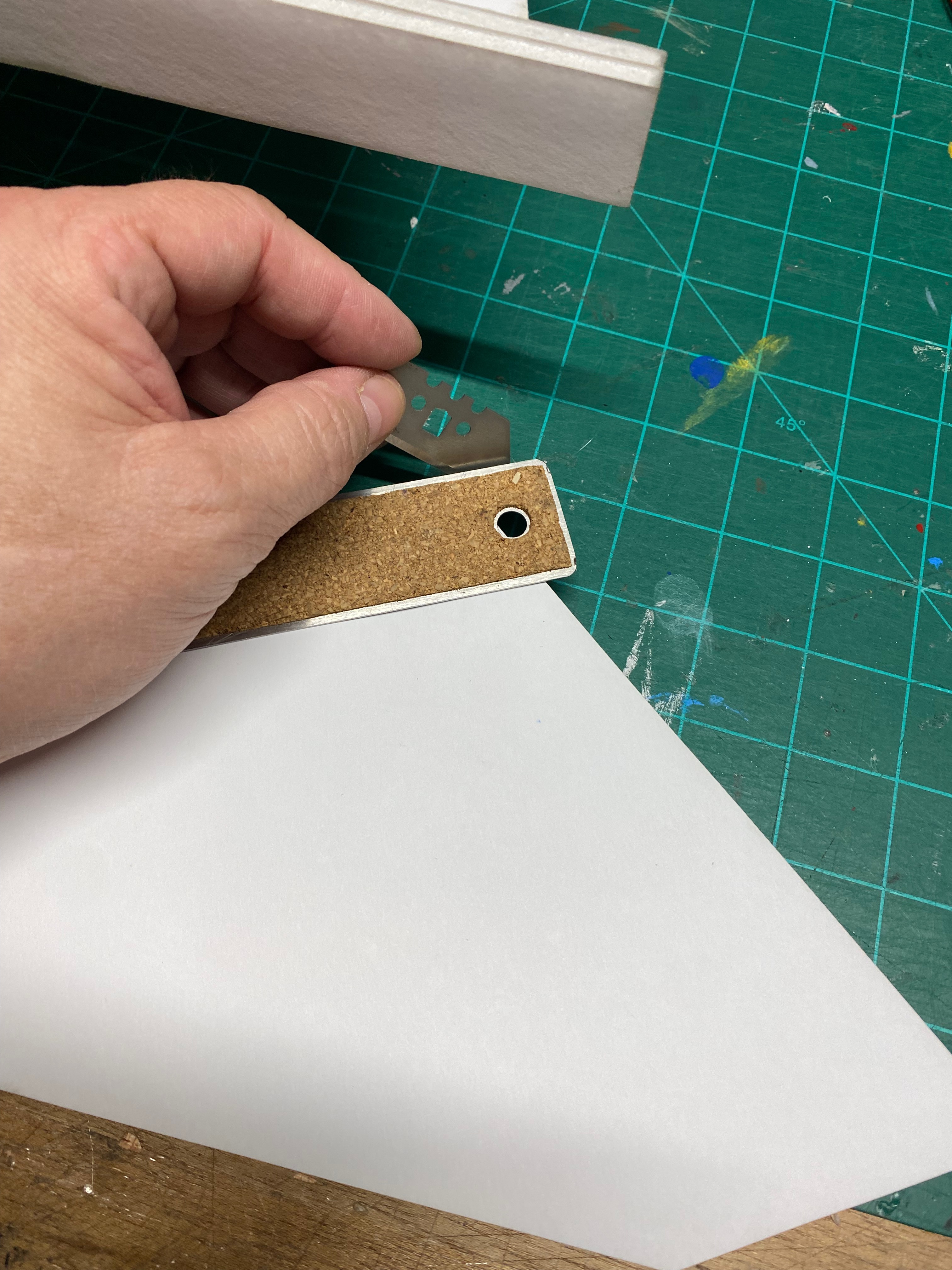
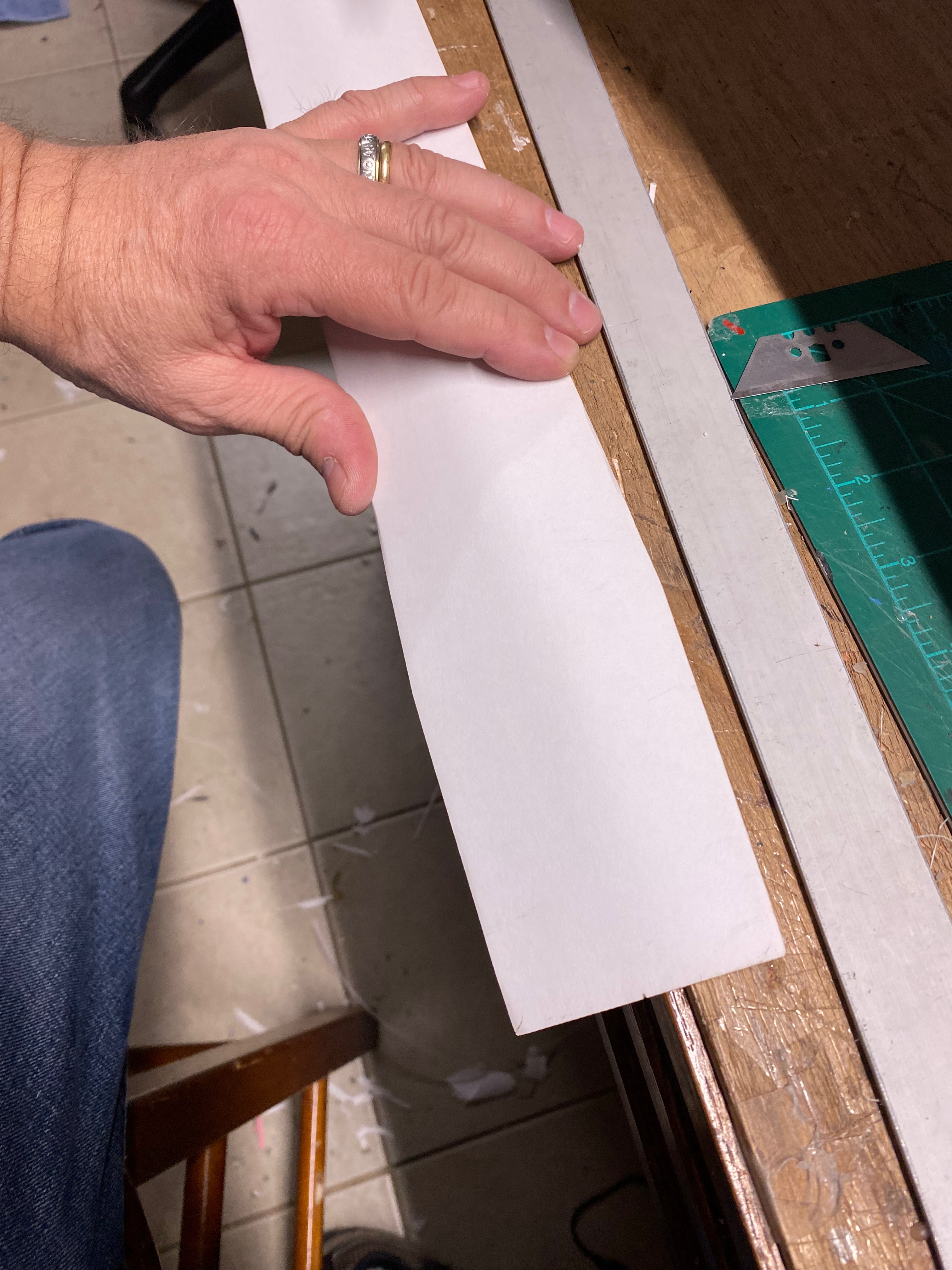
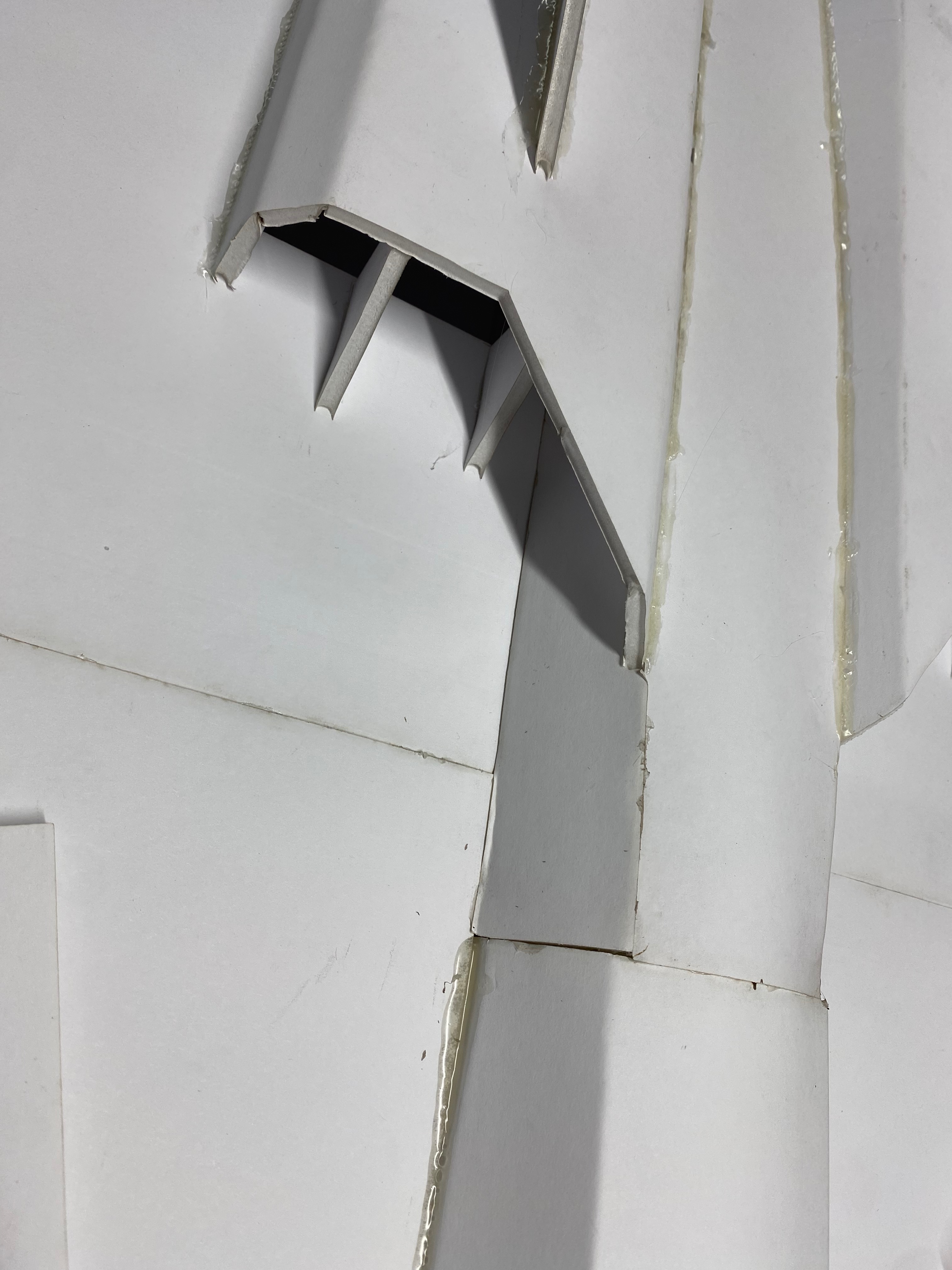
Find the 4 front wing triangle sections, gluing 2 of them together to make the 2 front wing sections.

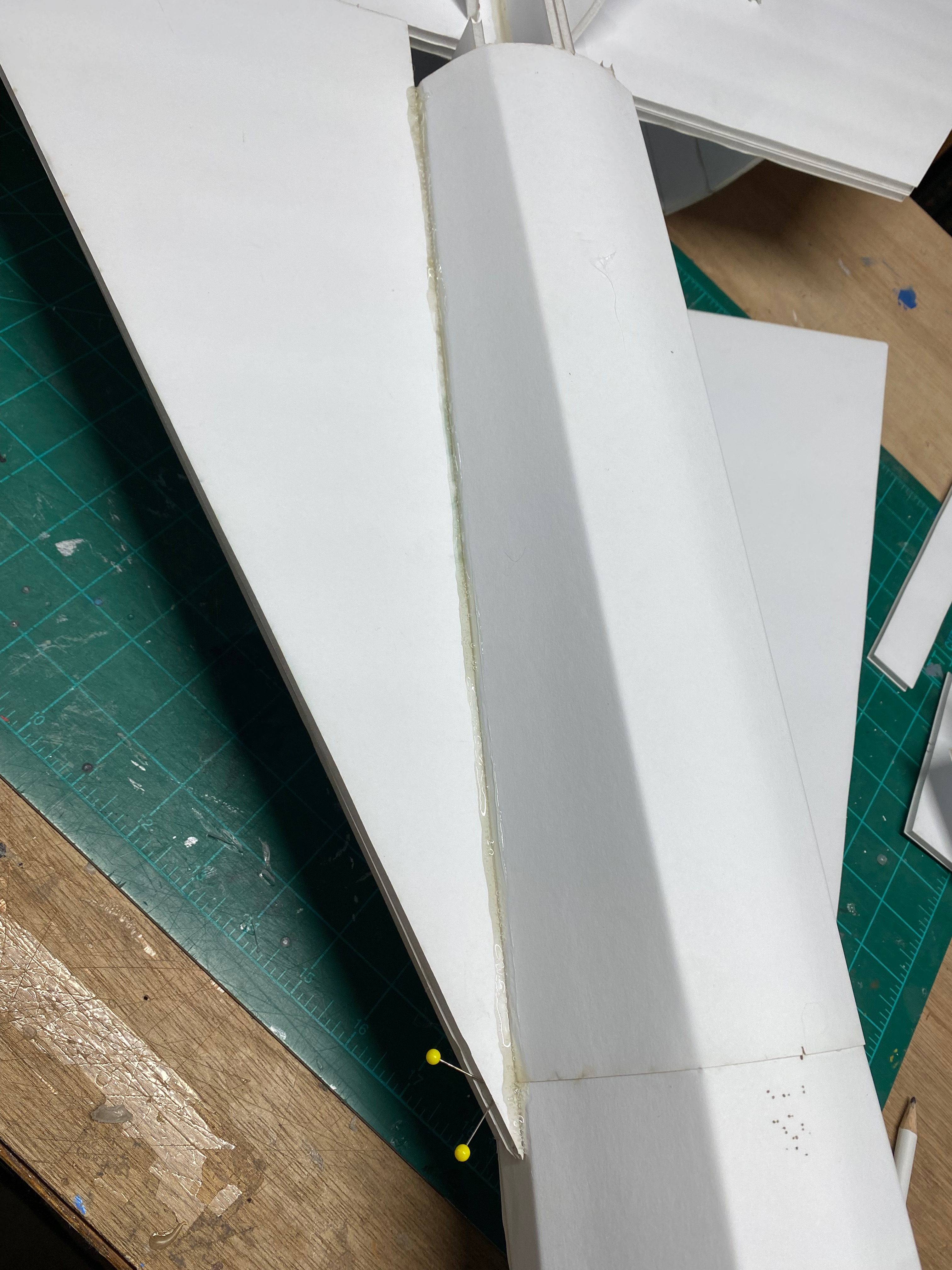
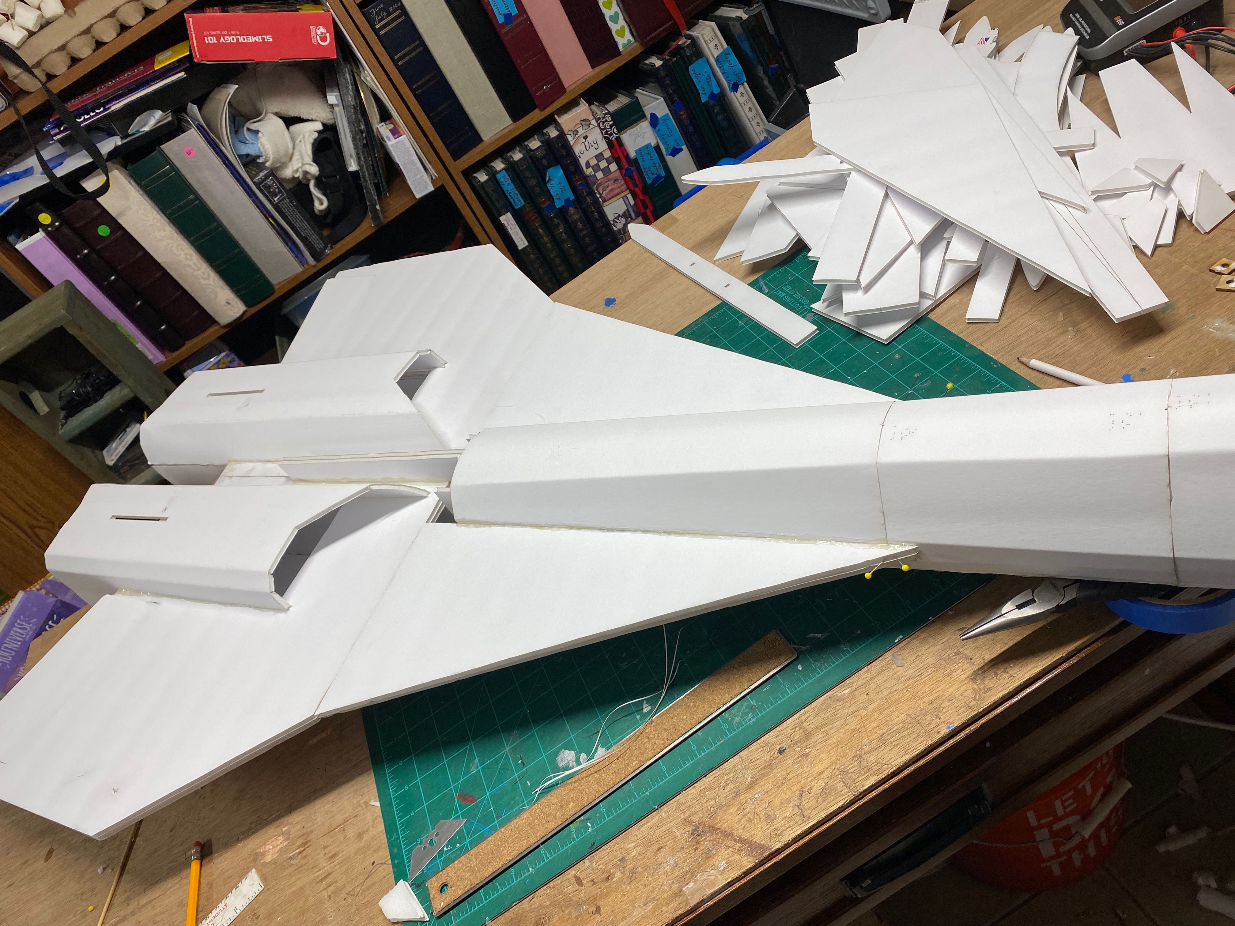
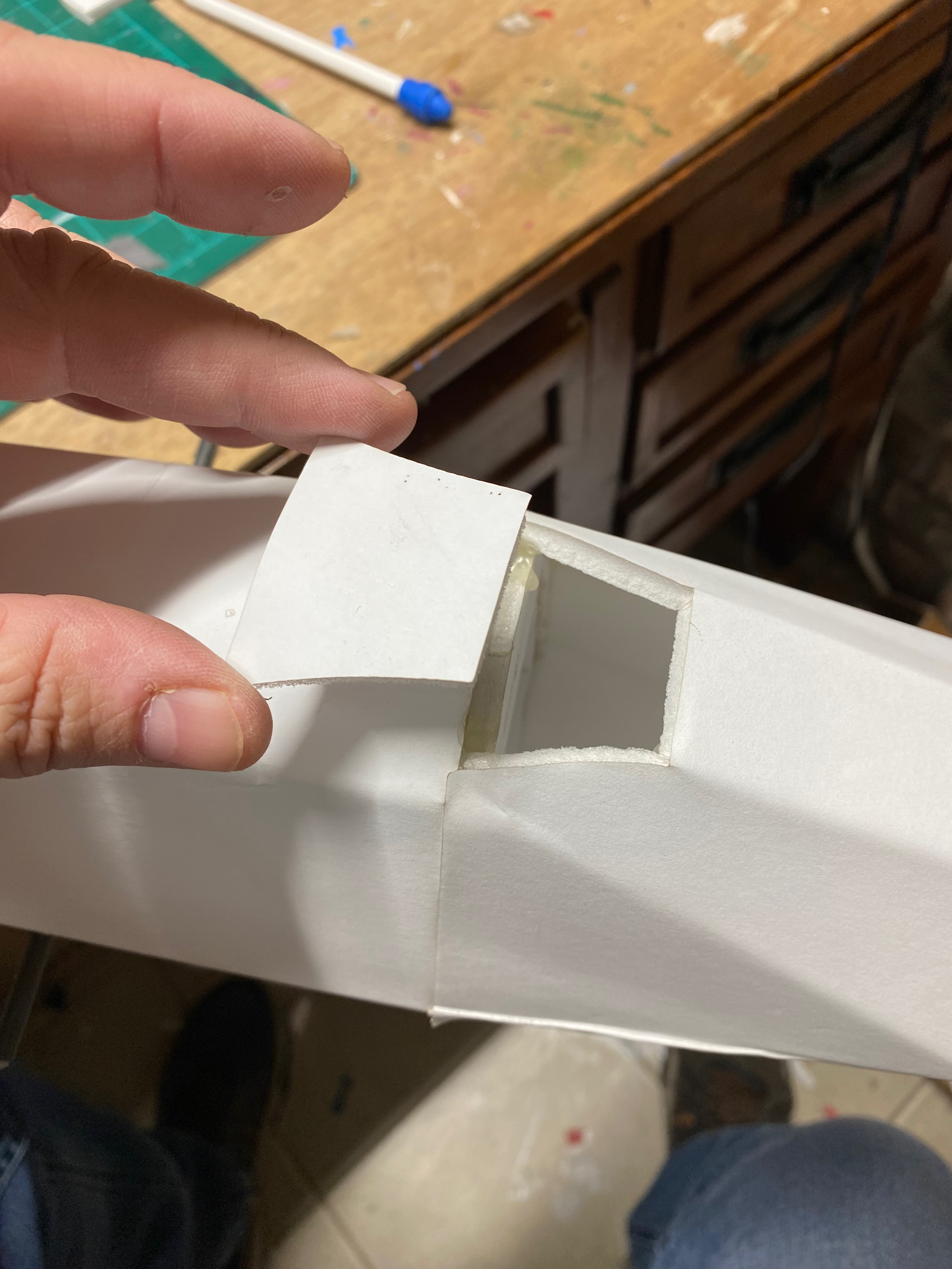
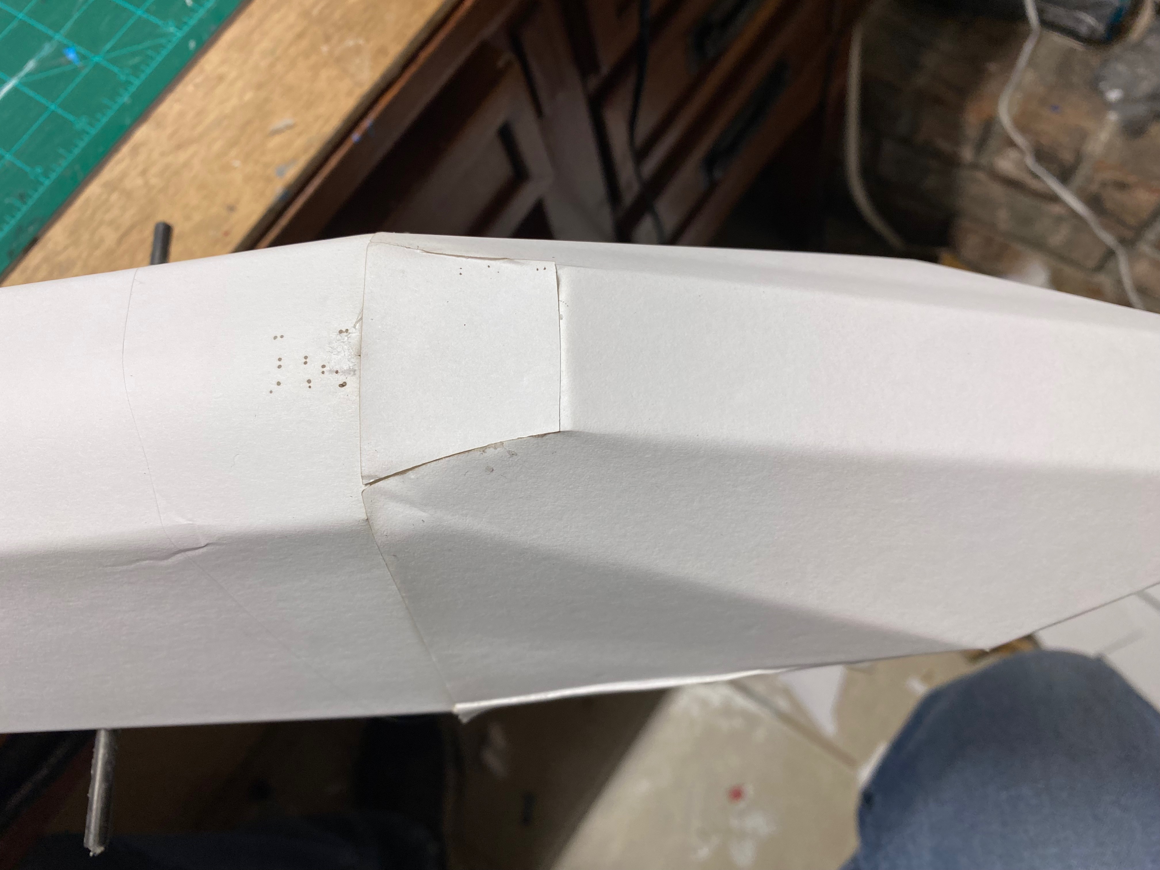
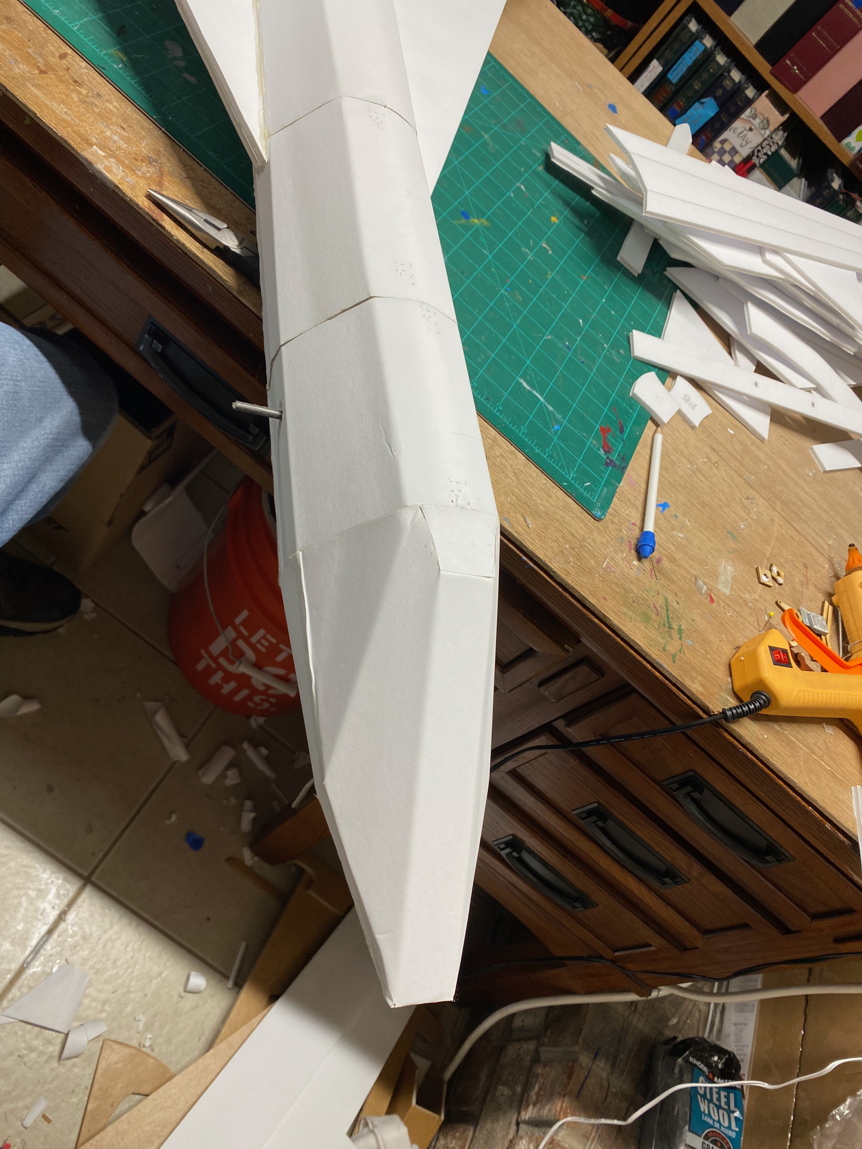
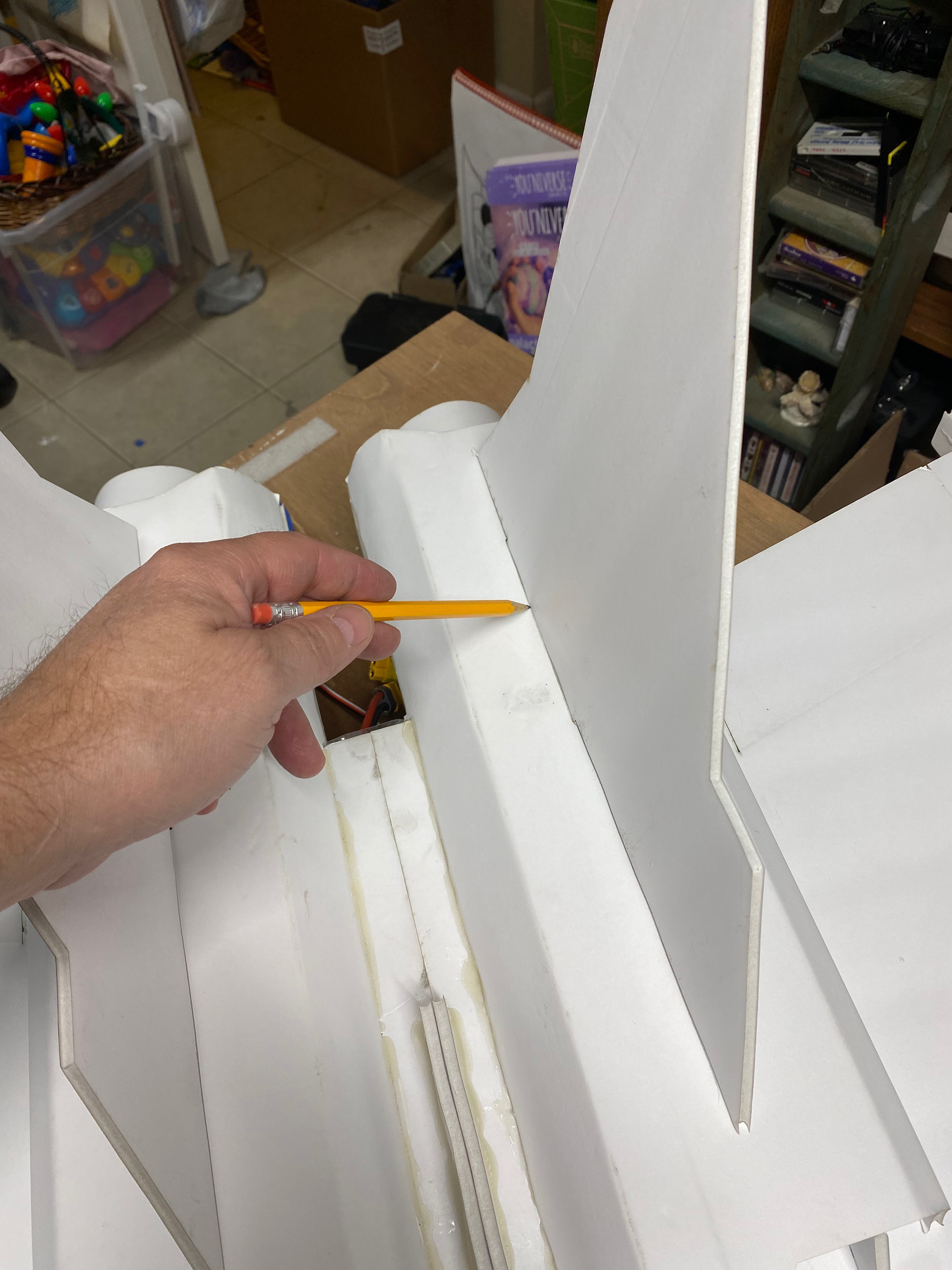
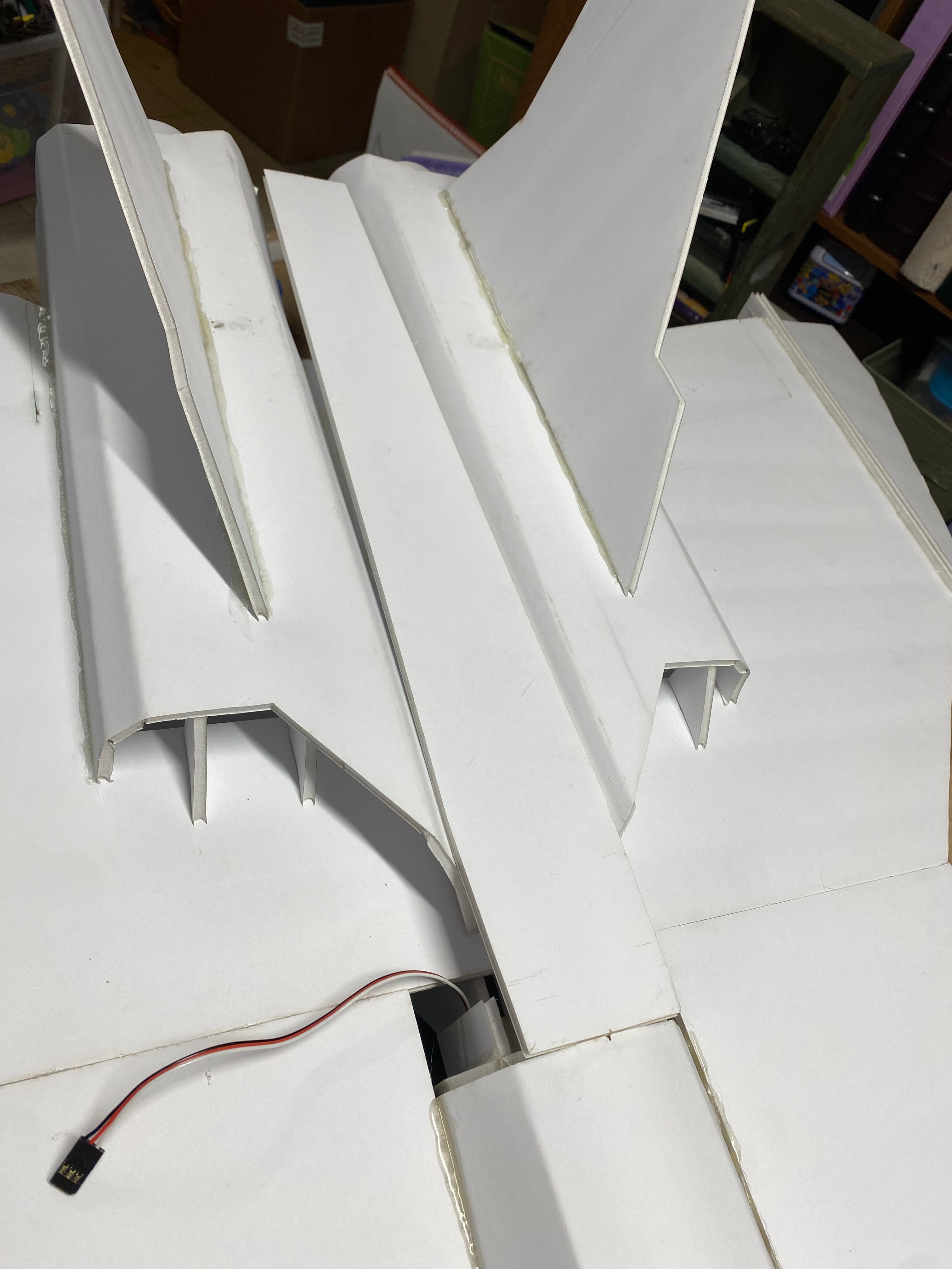
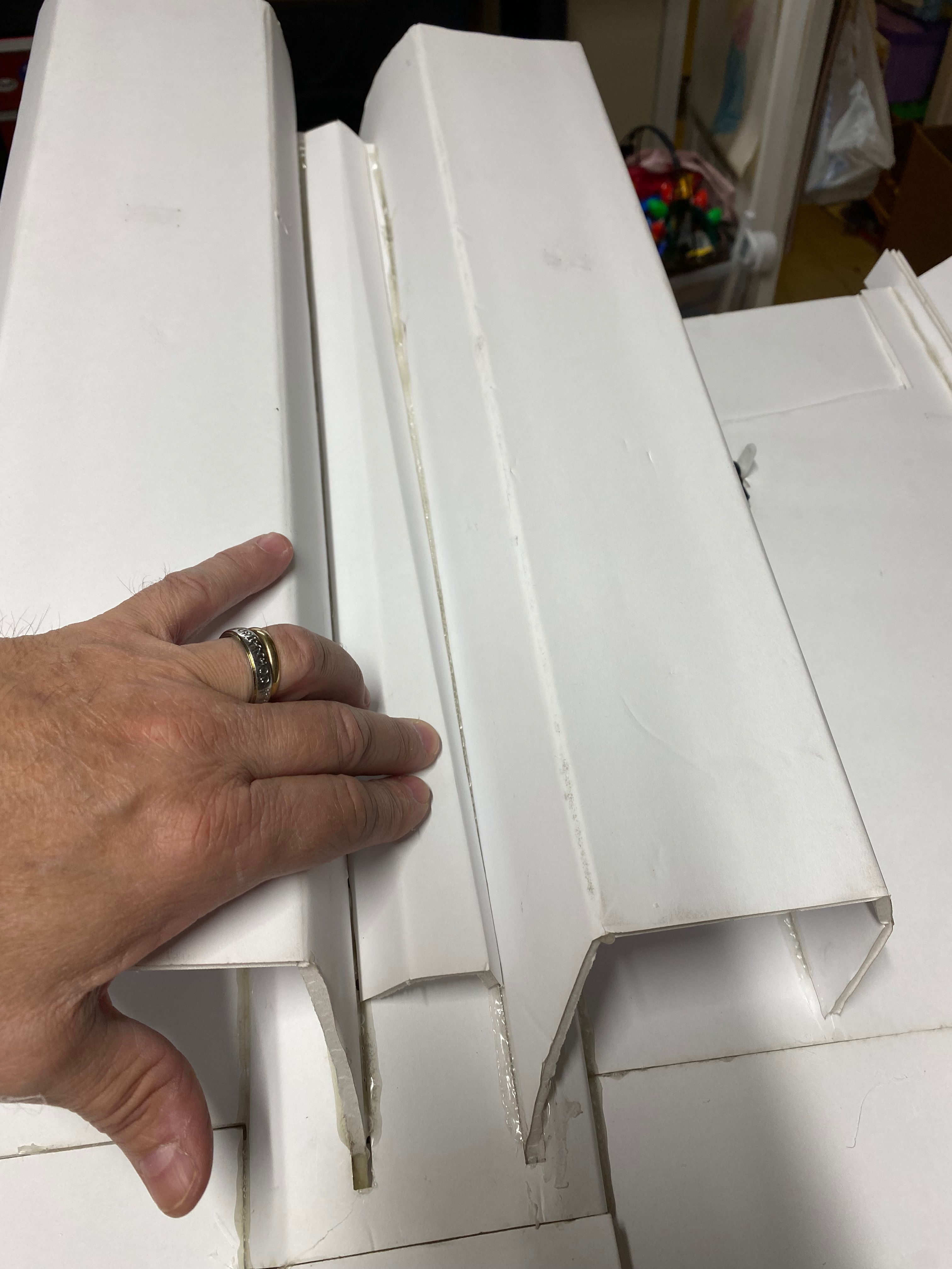
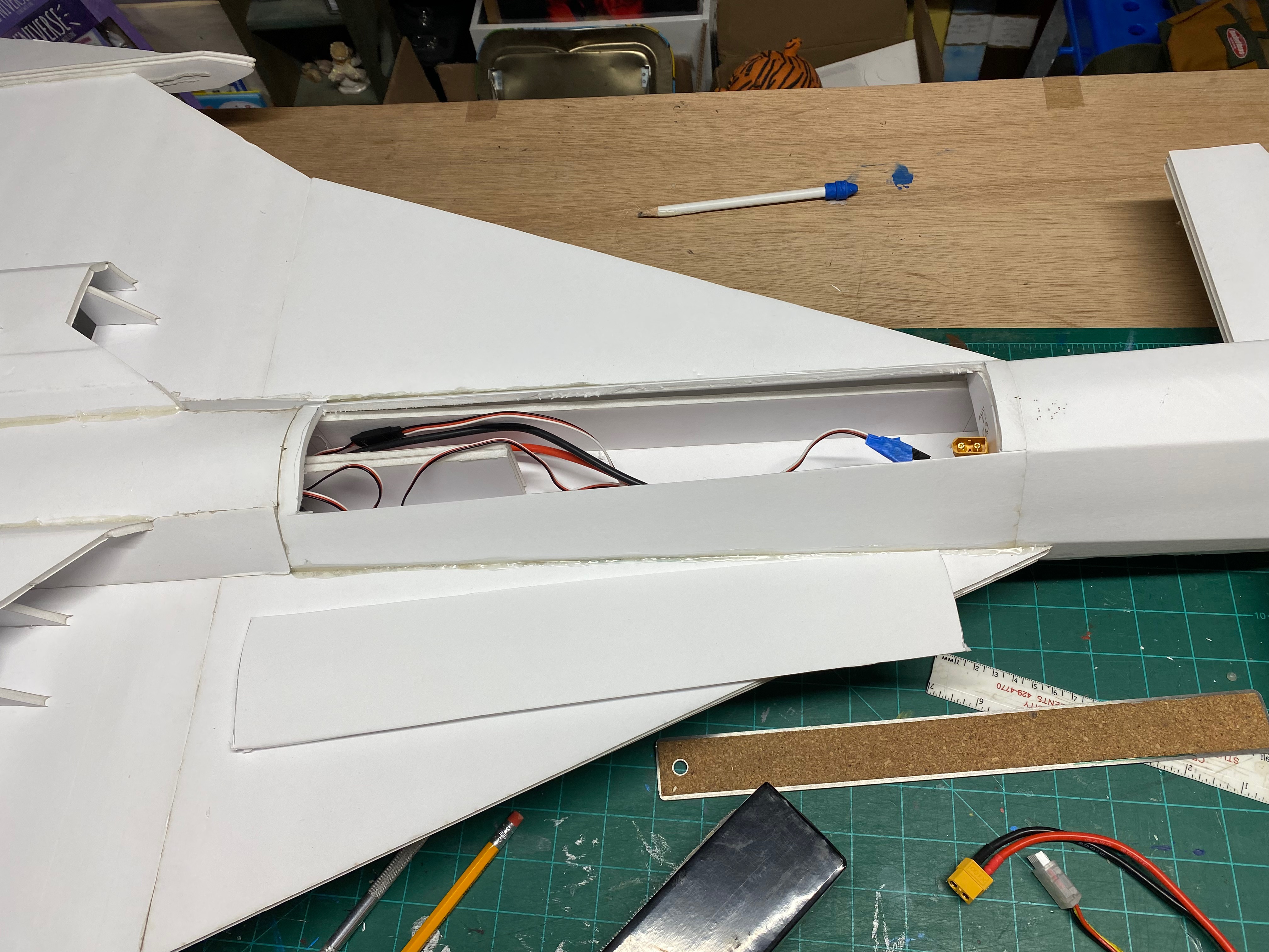
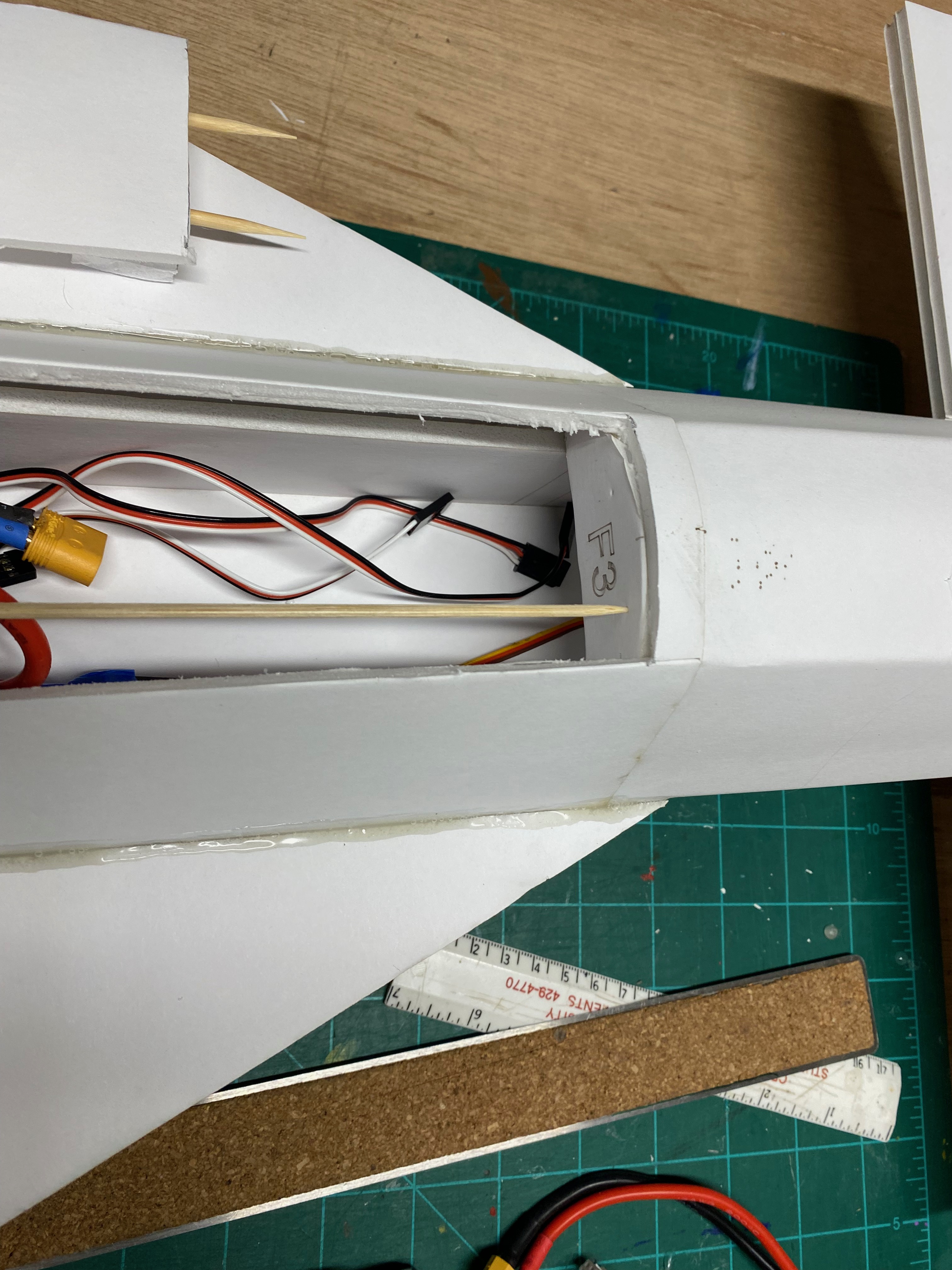
Slide the fuselage Battery tray onto the spline, all the way to where the notch in the spline rests against the F4 former. See pic. Do this on a flat surface, propping up the fuselage so that the fuse is perfectly in line with the wing both up and down, and side to side, and centered at the wing joint and spline. When satisfied with the placement, back the fuse off, apply glue to spline, and reposition and let glue dry. USE a SLOW drying glue or 5 minute epoxy for this joint so you have some working time to position the fuselage and wing to make the joint lined up well.
 

Attachments

  • IMG_9909.jpeg
    IMG_9909.jpeg
    1.9 MB · Views: 0
  • IMG_9910.jpeg
    IMG_9910.jpeg
    2.4 MB · Views: 0

noahangel11

Well-known member
After joint has dried, glue on the front wing winglets to the front wing edge and against the fuselage. This adds more strength.

NOTE: The final design has more forward facing wing area, to strengthen the joint where the wing meets the fuselage. Although these prices are currently outdated, the fit of the spline is the same.
 

Attachments

  • IMG_9911.jpeg
    IMG_9911.jpeg
    2.3 MB · Views: 0
  • IMG_9912.jpeg
    IMG_9912.jpeg
    2.3 MB · Views: 0
  • IMG_9913.jpeg
    IMG_9913.jpeg
    2 MB · Views: 0
  • IMG_9914.jpeg
    IMG_9914.jpeg
    1.9 MB · Views: 0
  • IMG_9915.jpeg
    IMG_9915.jpeg
    2.5 MB · Views: 0
  • IMG_9918.jpeg
    IMG_9918.jpeg
    2.1 MB · Views: 0

noahangel11

Well-known member
Evenly space out the engine intake fins on the top wing, 2 per intake on the top. Glue in place when satisfied with placement. Do the same for the bottom wing side intake fins.
 

Attachments

  • IMG_9917.jpeg
    IMG_9917.jpeg
    1.5 MB · Views: 0

noahangel11

Well-known member
Remove the paper from the scored side of the front nose bottom ski. Widen the score lines with a BBQ skewer, bend the joints to get them flexible. Do the same for the top nose skin.

Add a slight curve to the outer sheet sections on the lower skin. See pics.
 

Attachments

  • IMG_9919.jpeg
    IMG_9919.jpeg
    2.5 MB · Views: 0
  • IMG_9920.jpeg
    IMG_9920.jpeg
    2.8 MB · Views: 0

noahangel11

Well-known member
The nose skins attach to the F1 former, and then to each other, with a paper flap to seal up the seam between the top and bottom sheet. Taper the front nose surfaces where they meet to get a good fit, trim as necessary. Take your time.
 

Attachments

  • IMG_9921.jpeg
    IMG_9921.jpeg
    1.9 MB · Views: 0
  • IMG_9922.jpeg
    IMG_9922.jpeg
    1.8 MB · Views: 0
  • IMG_9923.jpeg
    IMG_9923.jpeg
    1.8 MB · Views: 0
  • IMG_9924.jpeg
    IMG_9924.jpeg
    1.6 MB · Views: 0
  • IMG_9925.jpeg
    IMG_9925.jpeg
    2.2 MB · Views: 0

noahangel11

Well-known member
Remove paper from the small top nose section, add slight curve, and bevel the edges to get a good fit into the top of the nose. Glue when satisfied with fit.
 

Attachments

  • IMG_9926.jpeg
    IMG_9926.jpeg
    1.7 MB · Views: 0
  • IMG_9927.jpeg
    IMG_9927.jpeg
    1.8 MB · Views: 0
  • IMG_9928.jpeg
    IMG_9928.jpeg
    2.3 MB · Views: 0

noahangel11

Well-known member
The front stabilizer fins glue together just like the wing sheets did. The bottom sheet has a groove that you need to remove foam from that is where the stabilizer axle goes.

NOTE: The images show a stabilizer axle that is considerably shorter than what you should have. I corrected the length after I put mine together. The axle should protrude all the way into the stabilizer groove.

Connect a servo tester or radio, and center the stabilizer servo. Glue the bottom and top halves of one side together over the stabilizer axle, leaving a slight gab between fuselage and fin. USE A SLOW DRYING or 5 minute epoxy for strength, and prop fin up underneath so it if horizontally level to fuselage. Let dry. Repeat for other side.
 

Attachments

  • IMG_9930.jpeg
    IMG_9930.jpeg
    2.6 MB · Views: 0
  • IMG_9931.jpeg
    IMG_9931.jpeg
    2.2 MB · Views: 0
  • IMG_9932.jpeg
    IMG_9932.jpeg
    2.2 MB · Views: 0
  • IMG_9933.jpeg
    IMG_9933.jpeg
    2.3 MB · Views: 0

noahangel11

Well-known member
Find the 2 exhaust tip skins, remove paper from one side, shape the sheets on a desk edge, and glue the rings together. Then glue them to the engine nacelle F2 formers over the thrust tubes.
 

Attachments

  • IMG_9935.jpeg
    IMG_9935.jpeg
    2.6 MB · Views: 0
  • IMG_9936.jpeg
    IMG_9936.jpeg
    2 MB · Views: 0
  • IMG_9937.jpeg
    IMG_9937.jpeg
    2.4 MB · Views: 0
  • IMG_9938.jpeg
    IMG_9938.jpeg
    2.5 MB · Views: 0
  • IMG_9939.jpeg
    IMG_9939.jpeg
    2.9 MB · Views: 0

noahangel11

Well-known member
Find the wing tip strakes and glue 2 matching pieces together, lining up the notches in the middle.
Note: The notches are not centered in the strake, so make sure to flip the pieces until the holes line up.

Use the 1/8” ply wingtip spars to set the angle of the wingtips downward, passing them through the strakes. Glue strakes to wing outer edges with spars facing down towards ground.

Take 2 wingtip sheets and match them together, The bottom sheet has the notched area for the spar to fit into, remove the foam from the channel. The top sheet has no notch. Glue the 2 halves together, then taper the mating edge so it will mate well with the strake. When satisfied with the fit, glue the wingtips in place onto the spars and the strake. Run beads of glue to reinforce joints.
 

Attachments

  • IMG_9939.jpeg
    IMG_9939.jpeg
    2.9 MB · Views: 0
  • IMG_9940.jpeg
    IMG_9940.jpeg
    2 MB · Views: 0
  • IMG_9941.jpeg
    IMG_9941.jpeg
    2.6 MB · Views: 0
  • IMG_9942.jpeg
    IMG_9942.jpeg
    2.1 MB · Views: 0
  • IMG_9943.jpeg
    IMG_9943.jpeg
    1.7 MB · Views: 0
  • IMG_9944.jpeg
    IMG_9944.jpeg
    2.2 MB · Views: 0
  • IMG_9945.jpeg
    IMG_9945.jpeg
    2.6 MB · Views: 0
  • IMG_9946.jpeg
    IMG_9946.jpeg
    1.7 MB · Views: 0
  • IMG_9947.jpeg
    IMG_9947.jpeg
    2.1 MB · Views: 0
  • IMG_9948.jpeg
    IMG_9948.jpeg
    2.2 MB · Views: 0
  • IMG_9949.jpeg
    IMG_9949.jpeg
    1.9 MB · Views: 0

noahangel11

Well-known member
Place a vertical stabilizer into the top notch on each engine nacelle. Lightly mark the location with a pencil on the nacelle to act as a glue line guide. Fins the triangle stabilizer angle guide, and then glue each stabilizer to the nacelle, running a bead along the pencil line guide. Keep holding at correct angle until glue dries, then run reinforcing beads of glue down each side of the vertical stabilizer to nacelle joint.
 

Attachments

  • IMG_9950.jpeg
    IMG_9950.jpeg
    1.8 MB · Views: 0
  • IMG_9951.jpeg
    IMG_9951.jpeg
    1.7 MB · Views: 0
  • IMG_9952.jpeg
    IMG_9952.jpeg
    1.8 MB · Views: 0
  • IMG_9953.jpeg
    IMG_9953.jpeg
    1.8 MB · Views: 0

noahangel11

Well-known member
Find the long top sheet that starts at the top of F4 former and fits between the engine nacelles. Remove paper from one side, add a slight curve shape to it, and test fit it. Taper the edge to get a good fit against the nacelle.
 

Attachments

  • IMG_9954.jpeg
    IMG_9954.jpeg
    1.7 MB · Views: 0
  • IMG_9955.jpeg
    IMG_9955.jpeg
    1.8 MB · Views: 0
  • IMG_9957.jpeg
    IMG_9957.jpeg
    2.3 MB · Views: 0
  • IMG_9958.jpeg
    IMG_9958.jpeg
    1.4 MB · Views: 0

noahangel11

Well-known member
Take the 2 notched side skins that cover this are in front of the engine nacelles. remove the paper, slightly bevel the edges, and glue into place from F4 former into the engine intake.
 

Attachments

  • IMG_9959.jpeg
    IMG_9959.jpeg
    1.9 MB · Views: 0
  • IMG_9960.jpeg
    IMG_9960.jpeg
    1.8 MB · Views: 0
  • IMG_9961.jpeg
    IMG_9961.jpeg
    2.4 MB · Views: 0

noahangel11

Well-known member
Find the qty2- F5 formers, glue them together. Turn model upside down and glue the former between the nacelles, with half the thickness sticking out from the top nacelle center sheet, at the rear of the plane.
 

Attachments

  • IMG_9967.jpeg
    IMG_9967.jpeg
    1.7 MB · Views: 0

noahangel11

Well-known member
Run all the wires along the space between the nacelles on the underside of the wing. You should have the ESC power wires, signal wires, and the 2 wing servo wires. Extend the wires as needed to reach into the fuselage about half way, and feed them up into the fuselage. Later when you cut a battery hatch out, you can access the wires.
 

Attachments

  • IMG_9967.jpeg
    IMG_9967.jpeg
    1.7 MB · Views: 0

noahangel11

Well-known member
Find the bottom wing to fuselage skin that fits between the nacelles. It has 2 notches in it. Remove the paper from the scored side and use a BBQ skewer to widen the score lines. Then flex the joint.

This sheet runs from F4 former back to F5 former and covers the wiring. Taper the edges that meet the nacelles, test fit the sheet in place, as it also slides into the engine intake and you may want to taper those edges where thy mate to inner surface of nacelle and wing. When satisfied with the fit, glue in place.
 

Attachments

  • IMG_9971.jpeg
    IMG_9971.jpeg
    2.6 MB · Views: 0
  • IMG_9972.jpeg
    IMG_9972.jpeg
    2.7 MB · Views: 0
  • IMG_9973.jpeg
    IMG_9973.jpeg
    1.7 MB · Views: 0
  • IMG_9974.jpeg
    IMG_9974.jpeg
    1.7 MB · Views: 0

noahangel11

Well-known member
There are 2 long pieces with scores in them that make up the lower fuselage scoop. Remove the paper from the score side, widen the scores with a BBQ skews, and bend into shape. Glue them starting at the rear F5 former, even with the sheet you are gluing it to, and work your way up with the 2 pieces. See pics for reference.
 

Attachments

  • IMG_9975.jpeg
    IMG_9975.jpeg
    1.8 MB · Views: 0
  • IMG_9976.jpeg
    IMG_9976.jpeg
    2.7 MB · Views: 0
  • IMG_9977.jpeg
    IMG_9977.jpeg
    2.7 MB · Views: 0
  • IMG_9978.jpeg
    IMG_9978.jpeg
    1.9 MB · Views: 0

noahangel11

Well-known member
Cut and make a battery hatch. Here is how I did mine:
I cut along the F3-F4 skin top corners and across the face of the formers, leaving enough allowance for the former thickness. I used 2 BBQ skewers to reinforce the hatch, but also to make posts that stick into the F3 former when you slide the hatch in place towards the front. I used soap foam to make a mount for the skewers at the front of the hatch. Then I slid it in place into F3, making marks where folks would be in the former, to receive the hatch skewers. I then used another skewer sharp ind to poke holes into f3 former.

I don’t have pictures, but the rear of my hatch was also reinforced with popsicle sticks, and I adde scrap foam and some rare earth magnets to hold the rear of the hatch in place. This worked well.
 

Attachments

  • IMG_9979.jpeg
    IMG_9979.jpeg
    1.8 MB · Views: 0
  • IMG_9980.jpeg
    IMG_9980.jpeg
    1.9 MB · Views: 0
  • IMG_9981.jpeg
    IMG_9981.jpeg
    2.1 MB · Views: 0
  • IMG_9982.jpeg
    IMG_9982.jpeg
    1.9 MB · Views: 0
  • IMG_9983.jpeg
    IMG_9983.jpeg
    1.7 MB · Views: 0
  • IMG_9984.jpeg
    IMG_9984.jpeg
    2.2 MB · Views: 0
  • IMG_9985.jpeg
    IMG_9985.jpeg
    2.2 MB · Views: 0
  • IMG_9986.jpeg
    IMG_9986.jpeg
    1.8 MB · Views: 0
  • IMG_9988.jpeg
    IMG_9988.jpeg
    2.1 MB · Views: 0
  • IMG_9989.jpeg
    IMG_9989.jpeg
    2.2 MB · Views: 0