Propeller area, spinner occlusion and other maths

Fluburtur

Cardboard Boy
I know, I hate maths unless it is practical for what I want to do.

I was rebuilding the nose of my 3d printed VG-33 (again) and was thinking about how I could increase the speed, right now it has loads of air torque but top speed is low, so I was thinking I could trade torque for speed without changing the power system.

Then I thought about how the spinner was blocking some prop area, in this case my propeller is a 10" triblade and the spinner is 70mm in diameter, there is also the hub of the propeller that is 23mm in diameter and won't produce thrust anyways unless something is seriously wrong.
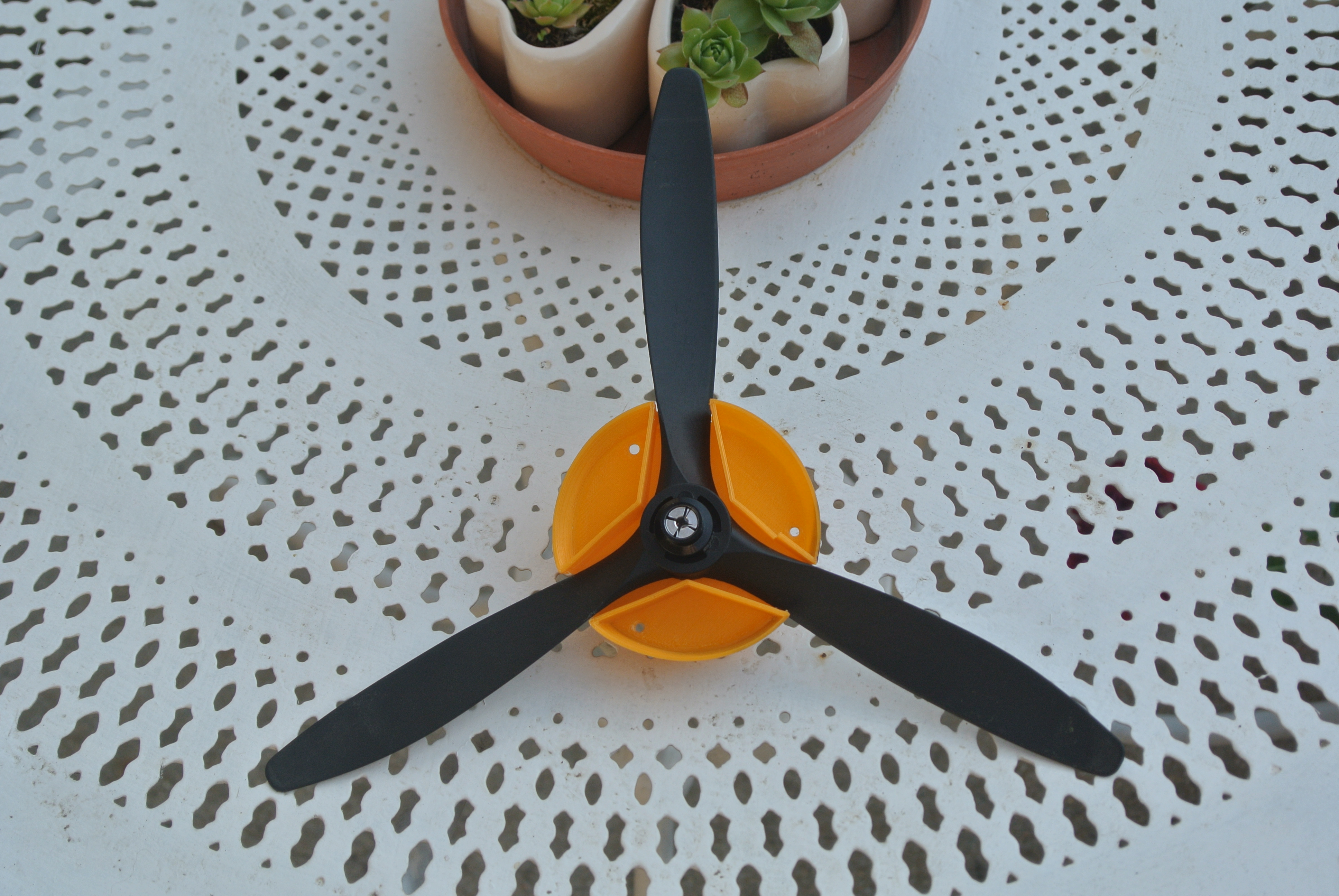
DSC_9507.JPG

I always use this calculator for my RC stuff so I will assume it is somewhat accurate and it seems to be from my experience.

Anyways, I then calculated the area of the prop and stuff like that and the results are as follow:
Area of the prop excluding the hub: 502.6 cm² (the calculator thinks the whole diameter of the prop is producing thrust, if I include the hub it is 506.7 so close enough)
Area of the propeller minus spinner: 494.9 cm²

As you can see the difference isn't big, the area of the prop with spinner is equivalent to that of a 9.8" propeller however so far I have been ignoring RPM and pitch. My initial goal was to find a rule of thumb to get correct propeller size when using a spinner that covers part of it however the change in area isn't significant at that scale, the difference would be more important with a smaller propeller or larger spinner.

I initially planned to put a prop larger by 1" on that but then I think I would only lose efficiency and adding more pitch for the same diameter would also lower efficiency so I would need to put a smaller, more pitchy prop on the plane but that would kinda ruin the scale looks.

There is also the fact that a slightly larger propeller will produce more thrust in a non linear way because the speed of the propeller will get higher the furter away from the center if keeping the same RPM.

Im now realizing that this thread is turning into "help me build a better power system" but there is probably something I overlooked and that problem is worth thinking about I think.
 
  • Like
Reactions: Inq

Tench745

Master member
I think your losses due to the spinner are minimal. First off, the fuselage is already blanking off a portion of the prop and making it ineffective. The spinner, if it's doing anything, is reducing the work the motor has to do by streamlining the ineffective portion of prop. This means the motor can spin the prop at a higher RPM with the same amp draw, thus producing slightly more thrust than without a spinner. Once you get to something that is almost all cowl, like a dummy radial, you do need to up the diameter to get the effective blade area to a reasonable amount. Likewise, if you go to a larger scale the differences in area become more meaningful.

If your goal is to increase top speed and decrease torque (thrust) You could move to 2 blade with a higher pitch and/or larger diameter.
Similarly, you could decrease the diameter of your 3 blade and increase pitch to keep a similar amp draw.
The key is balancing pitch, diameter, number of blades, and RPM to get you the speed you need within the amp draw your system can handle.
 

Fluburtur

Cardboard Boy
Well the plane is question is very streamlined, there might be some fairly high loss to skin friction however since it is 3d printed and not smooth.

Good point on the increase in RPM because less of the prop is used, I haven't thought about that. When entering in the calculator the diameter of a prop with the same area as the prop with spinner it does give me a bit higher RPM.

I want to keep the scale Look so I can't make it two blades or smaller (I might try to get a very speedy aircraft however) and increasing the pitch would affect efficiency rather badly so I guess I can try to change the prop slightly and use higher voltage battery.

Of course I will also need to try all that on a fiberglass version of the aircraft since it will be smoother, weight shouldn't change too much so that will be interesting to compare the impact of fuselage aerodynamics.
 

Hai-Lee

Old and Bold RC PILOT
Your issue sounds like the same issue that aircraft manufacturers had in the early 1930's which was only resolved with the introduction of 2 speed and later constant speed propellers.

With all the 3D printers around and the number of individual propeller blades available perhaps someone could design and print up a variable pitch spinner/hub which could go some way to resolve the balancing act you are attempting.

Have fun!
 

Fluburtur

Cardboard Boy
I could try, not many rc airplanes have those but I can think of one

However it would be kinda hard to do for the production aircrafts I want to sell, also it would need a way of knowing the current airspeed to adjust the speed which could be done mechanically by having some arm poking out somewhere acting sort of like a pitot tube, otherwise it would need electronics.

I will probably try that but as I said, would be hard to implement beyond a few prototypes and durability will most likely be an issue.
 

Hai-Lee

Old and Bold RC PILOT
I could try, not many rc airplanes have those but I can think of one

However it would be kinda hard to do for the production aircrafts I want to sell, also it would need a way of knowing the current airspeed to adjust the speed which could be done mechanically by having some arm poking out somewhere acting sort of like a pitot tube, otherwise it would need electronics.

I will probably try that but as I said, would be hard to implement beyond a few prototypes and durability will most likely be an issue.
I made a few notes for future use should I ever get a 3D printer or similar and actually require such a device but in simple form there are a few aspects of propeller operation that can be used for a simple pitch control mechanism.

1. Motor/propeller speed can be roughly measured through the centrifugal force generated. The faster the prop spins the greater the force generated trying to fling the prop away from the hub.

2. Motor speed is effectively determined by the load on the motor which is due to blade drag and the power used to generate thrust. For a given pitch as the plane speed increases the propeller load will decrease and normally the motor speed will increase, (observable in a gravity assisted high speed run when doing speed tests.

So whilst not a perfect system a simple system could be attained but using the centrifugal forces as a method to change pitch would allow for a moderate pitch adjustment that is repeatable, simple, and similar in operation to the original 2 speed propeller hubs.

At lower propeller speeds the pitch would be at the finer setting and on take off the loading would somewhat maintain the pitch angle by loading the prop. As the plane speed increases the prop would reduce its loading and the rotational speed would increase. This rotational speed speed increase would generate greater centrifugal forces and cause the blade pitch angle to increase thereby apply a slightly greater blade loading at a higher pitch.

By ensuring that all the prop blades are linked physically to each other to maintain equal blade angle you would end up with a prop that has a fine pitch angle for take off and a coarse pitch angle for high speed performance all without any setup or pilot input.

Anyway that is just some of the preliminary notes from one of my research/idea projects, (still to be finalised).

Just my thoughts Etc!

have fun!
 
  • Like
Reactions: Inq

Fluburtur

Cardboard Boy
So in short, your idea is to have a propeller that tries to always maintain the same load? that's rather smart, it could also be tuned so it is very efficient.

I might PM you when I start working in that.
 

Hai-Lee

Old and Bold RC PILOT
So in short, your idea is to have a propeller that tries to always maintain the same load? that's rather smart, it could also be tuned so it is very efficient.

I might PM you when I start working in that.

Any time! I seriously need to get a decent, (or any), 3D printer!! Anyway back to work!

have fun!
 

quorneng

Master member
Fluburtur
I think you are rather over looking how little the inner 1/4 of any prop blade actually contributes to the total thrust. This effect get worse as the air speed rises!
If you look at a full size variable pitch prop in high speed cruising flight the blade is rotated so much that the inner part is almost inline with the airflow to minimum drag rather than generating significant thrust.
A well streamlined shaped spinner that exactly matches the line of the fuselage is the way to go for minimum drag and thus maximum performance.
 

Hai-Lee

Old and Bold RC PILOT
Fluburtur
I think you are rather over looking how little the inner 1/4 of any prop blade actually contributes to the total thrust. This effect get worse as the air speed rises!
If you look at a full size variable pitch prop in high speed cruising flight the blade is rotated so much that the inner part is almost inline with the airflow to minimum drag rather than generating significant thrust.
A well streamlined shaped spinner that exactly matches the line of the fuselage is the way to go for minimum drag and thus maximum performance.
You are correct with your statement for the most part.

A streamlined spinner covering the high drag central portion of the propeller is a given BUT a spinner can be too large and actually rob a propeller of a percentage of its trust generating area especially in high speed flight.

So it is important to get a spinner to fuselage profile that provides a smooth transition for the air flow but the propeller must be large enough so that the spinner does not rob it of high speed thrust.

Matching everything for the optimum high speed performance is not an easy task especially when propeller profiles differ from manufacturer to manufacturer.

Have fun!