Designing Propellers

Inq

Elite member
I think this question is up your all's experience (@telnar1236, @quorneng) but if anyone else can help... pile on! ;)

I want to design a folding, geared propeller. For this experiment, I'll be using a Flash Hobby BE1806, 1400KV motor and 3S power. I have two stock propellers (6x3.5 Orange, 6x4 Grey) that are (I guess) the typical for this motor.
PXL_20230307_140325676.jpg
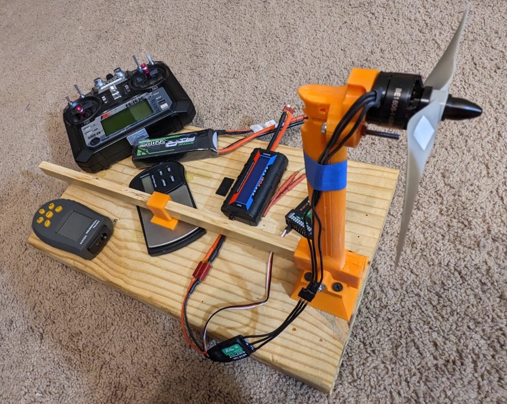
I'll benchmark both of these to get a baseline static thrust using my Dynamometer.
Dyno.jpg
I want to design something like this... folding, geared propeller.
PXL_20230307_140405137.jpg

What I'm looking for:
I'll know the motor RPM, current draw and thrust using the two baseline propellers. I know that if I have a reduction gear ratio, I can swing a bigger propeller and/or a different pitch propeller. The two things I'm looking for are:
  1. Knowing the diameter, rpm and pitch it's pretty simple Math to determine the theoretical maximum speed of the plane. However, from a practical standpoint with scale issues and DIY propeller issues, what kind of slip percentage should I use? IOW... will the actual maximum speed of the plane be 50% of the theoretical or 95%?
  2. What would the equation look like to try to compare apples and oranges of different propellers? I'm just looking for a ballpark equation so I can say something like... "With a 1:3 gear reduction, I can swing a 10x6 propeller and the motor will be spinning the same speed and using the same current as with the 6x3.5.
What I'm guessing with what I know already - All I'm trying to do is reduce the number of iterations. I'm not expecting to nail it on the first prop!

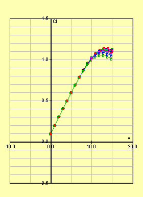
(1) As long as I stay in the linear range of a propeller's airfoil, I'm thinking that power required should be linear WRT pitch angle. K = Pitch * rpm
1678200121500.png


(2) Knowing that drag on a foil is a function of velocity squared, and velocity is a linear function of diameter, I'm guessing.
K = Diameter * rpm^2.

What I'm coming up with in my simplistic concept is K = Pitch * Diameter * RPM^2 should be a first cut estimate that I'd print up and see how it works. If it draws too much power, I reduce the pitch or diameter or vice versa, if I'm not using enough power, I up one or the other.
 
Last edited:

telnar1236

Elite member
I think this question is up your all's experience (@telnar1236, @quorneng) but if anyone else can help... pile on! ;)

I want to design a folding, geared propeller. For this experiment, I'll be using a Flash Hobby BE1806, 1400KV motor and 3S power. I have two stock propellers (6x3.5 Orange, 6x4 Grey) that are (I guess) the typical for this motor.
View attachment 236074
I'll benchmark both of these to get a baseline static thrust using my Dynamometer.
View attachment 236075
I want to design something like this... folding, geared propeller.
View attachment 236076

What I'm looking for:
I'll know the motor RPM, current draw and thrust using the two baseline propellers. I know that if I have a reduction gear ratio, I can swing a bigger propeller and/or a different pitch propeller. The two things I'm looking for are:
  1. Knowing the diameter, rpm and pitch it's pretty simple Math to determine the theoretical maximum speed of the plane. However, from a practical standpoint with scale issues and DIY propeller issues, what kind of slip percentage should I use? IOW... will the actual maximum speed of the plane be 50% of the theoretical or 95%?
  2. What would the equation look like to try to compare apples and oranges of different propellers? I'm just looking for a ballpark equation so I can say something like... "With a 1:3 gear reduction, I can swing a 10x6 propeller and the motor will be spinning the same speed and using the same current as with the 6x3.5.
What I'm guessing with what I know already - All I'm trying to do is reduce the number of iterations. I'm not expecting to nail it on the first prop!

(1) As long as I stay in the linear range of a propeller's airfoil, I'm thinking that power required should be linear WRT pitch angle. K = Pitch * rpm
View attachment 236077

(2) Knowing that drag on a foil is a function of velocity squared, and velocity is a linear function of diameter, I'm guessing.
K = Diameter * rpm^2.

What I'm coming up with in my simplistic concept is K = Pitch * Diameter * RPM^2 should be a first cut estimate that I'd print up and see how it works. If it draws too much power, I reduce the pitch or diameter or vice versa, if I'm not using enough power, I up one or the other.
Generally, modern brushless motors are pretty well tuned to the optimal speeds for the propellers they use. Much slower and you lose too much from the top end speed and too much faster and efficiency and static thrust suffer. You can spin a larger propeller with gears, but you get losses from the gears so most of the time it's more efficient to just use a larger diameter, slower motor. However, for the sake of experimentation, it definitely should save money over buying a ton of extra motors.

1. It's highly dependent on the plane. You're theoretical top speed in level flight is when your ratio of drag to lift is equal to your thrust to weight ratio. To estimate performance with any accuracy, you need a ball park drag polar (lift vs. drag plot) and a ball park thrust curve with speed. You can then find the coefficient of lift required for level flight at a given speed, find the D/L value from the drag polar at that point, and compare it to your thrust to weight ratio. This is the polar I generated for my F-104 using CFD and it's pretty typical for an EDF without a delta wing (delta wings get strange at high angles of attack).

236086

Since the approach with the drag polar is pretty hard to do, a simpler method is to estimate a constant Cd and just find when the thrust is equal to the drag. A good Cd estimate is probably about 0.1 - 0.2 for a foam board plane (calculated from wing area), but it could be lower or higher depending. You can approximate the thrust curve by assuming constant efficiency, but this is pretty inaccurate for hobby props (really anything that doesn't have a constant efficiency), so you might need to look into that a bit more.

2. The fan affinity laws are a good tool for roughly estimating how much power a propeller will use if you scale it up or down with no other changes. They only work so far, though, so keep in mind that they have limitations.
Fan Affinity Laws (engineeringtoolbox.com)
 

Inq

Elite member
  1. Yes, this makes sense. I was over simplifying the concept. I'm looking for efficiencies in a climbing propeller for a powered glider. I know I'll need a certain minimum speed for climbing and I know for a given pitch and rpm, it has a theoretical top speed based solely on it moves say... 6 inches/rev. But I also know it slips. So I was looking for a baseline for a minimum pitch /rpm to achieve say 20 mph. But I see... that the planes drag is what causes the slip.
  2. Perfect... what I needed.
I know that there are efficiency gains by using a larger propeller and turning it slower. My test here
https://forum.flitetest.com/index.php?threads/diy-motor-dynamometer.71186/#post-736111 illustrate that clearly. Using motors of the same physical size, but different KV clearly shows that the slowest... swinging the 10 prop creates more thrust per watt used. I understand it sacrifices top speed capability for this efficiency gain, but I'm not needing high top speeds. The bigger prop is 35% more power efficient. Basically, I'm working at the opposite end of the spectrum from an EDF.

I'm hoping to find that effectively making it a lower KV will make it more efficient than the frictional losses. For instance if say I use a 1:5 gear ratio. The effective KV is now 1400/5 = 280 and this allows me to swing say a 12x4 prop. Logic says it'll create far more thrust. Now... will the frictional losses eat that up? Much of that depends on the 3D printing quality of the gears. I'm willing to run the experiment and find out. Even if I just break even, I'll get a cool folding prop out of it.
 

dap35

Elite member
Looks really interesting. Just be careful when you are testing this with plenty of shielding in case the blades fail.
 

Inq

Elite member
Haven't decided if its a minor set-back or a major auger-in job.

Summary
I've used the 3D printed gears in several projects before, but nothing turning at this speed. I've also never used a gear with only four teeth. Usually the recommendation is seven or more. I'm getting far more loss than I expected and most of it in noise. I have two more ideas to quantify the problem.

Details
Thanks to @telnar1236 pointing me to some references. I wasn't too sure since it said centrifugal fans, but it was better than what I had. This equation basically represents the power needed based on geometry and speed. The units of K don't really matter and metric or imperial can be used. The point... is that we want the motor to feel it's turning the same propeller using the same power and turning the same speed.

K = Pitch * Diameter^5 * rpm^3.

Using the above baseline data...

K = 4 * 6^5 * 13200^3 = 7.15E16

Since the gear reduction is 4/13 the new propeller speed should be 4062 rpm. I put this into a spreadsheet so I could vary the pitch and see what diameter I get... I finally settled on a 10.1 x 10 propeller.

Diameter = (7.15E16 / 4062^3 / 10) ^ 0.2 = 10.1"
236156


Results
Thrust: 180 grams - Dismal!
Speed: 4300 rpm
Power: 49 watts

I take from this... that either the equation isn't accurate but... I prefer to think its the blades flattening out under load and thus not creating as much lift or drag. That would explain the lower power, and thrust and higher rpm than predicted.

Videos
The first vid shows the prop running at normal speed and making all kinds of racket! The second vid shows the prop at 8x slow motion. It almost sounds like a full scale turbo prop starting up! :LOL:


Next
  1. My current geometry was a little tight. The gears are made of Nylon (white) and rest is ABS (Orange). Because of the mismatch in thermal expansion, the gears are pressed into each other a little more than I'd like and might be the issue. I'll just upsize the gap between them by a couple tenths of a millimeter.
  2. Beef up the blades to resist loads a little better.
  3. Up the pitch/diameter even more
  4. I might make a direct drive unit to test if its the aerodynamics of the prop blades
 
So… I’m thinking you need to do an apples to apples comparison here.

If you can determine the motor rpm and dial it down to spin an unmodified prop before spinning it on your gear drive so you can determine your losses in the gears.

Your putting a lot of work into spinning these slower… it just seems you’re better of spinning slower straight from a motor before you add in the complexity of the gear drive. Tackle it one variable at a time and you can eliminate a lot of noise in your results.

That’s a slick test rig you’ve got there too! One thought from engineering school… your prop will give different thrust at different air speeds. After you figure everything else out, it’d be neat to put a fan in front of it and compare the thrust of different designs.

I wish I had been able to stick with the extracurricular aero project in hindsight… classes really got in the way of having fun when I got to college!
 

Inq

Elite member
If you can determine the motor rpm and dial it down to spin an unmodified prop before spinning it on your gear drive so you can determine your losses in the gears.

Your point is well taken... to only vary one variable at a time. Two ways I can go about it...

(1) I want the folding prop more than the bigger prop, if the gearbox is the problem. It would make sense to making a folding prop that is direct drive and iterate on blade design till I get adequate correlation with the baseline.

(2) Make a gearbox that can turn a standard but far larger propeller. The biggest I have on-hand is a 10x6. The problem with this route is it requires a whole different design of gears and gearbox. The prop has to be rigidly mounted to the gear (at the center) but the gear needs to have a shaft turning at the same center. It's possible, but a LOT heavier, bulkier and probably would require ball bearings and defeats the purpose of a light weight power glider rig.

I'm printing the modified gearbox with larger clearances at the moment and I'll start on version #1 in CAD.
 

Inq

Elite member
Were the blades bending forward or was that optical illusion?

I think that's optical illusion. Must be something about the way the values of pixels in the sensor are read. They can't all be read at the same instant, so the milliseconds it takes to scan left to right and top to bottom means we get the out of body experience. In some frames it looks like there's more than one set of blades... with some that aren't even connected. :LOL:
 

Mr NCT

VP of SPAM killing
Moderator
Yup, it's all in the signal processing. I've got an ancient speedgraphic camera with a shutter slit that travels from top to bottom. It gives the classic forward leaning oval effect to wheels on a moving vehicle.
 

Inq

Elite member
Test 2...
Second test using a slightly gapped gearbox did make things looser, but did not appreciably boost the numbers.

Am printing out a folding blade, direct drive hub and blades at 6x4. It's basically the same blade design, so I'm expecting bad results, but it will be all the blade's fault.

236164
 

telnar1236

Elite member
Haven't decided if its a minor set-back or a major auger-in job.

Summary
I've used the 3D printed gears in several projects before, but nothing turning at this speed. I've also never used a gear with only four teeth. Usually the recommendation is seven or more. I'm getting far more loss than I expected and most of it in noise. I have two more ideas to quantify the problem.

Details
Thanks to @telnar1236 pointing me to some references. I wasn't too sure since it said centrifugal fans, but it was better than what I had. This equation basically represents the power needed based on geometry and speed. The units of K don't really matter and metric or imperial can be used. The point... is that we want the motor to feel it's turning the same propeller using the same power and turning the same speed.

K = Pitch * Diameter^5 * rpm^3.

Using the above baseline data...

K = 4 * 6^5 * 13200^3 = 7.15E16

Since the gear reduction is 4/13 the new propeller speed should be 4062 rpm. I put this into a spreadsheet so I could vary the pitch and see what diameter I get... I finally settled on a 10.1 x 10 propeller.

Diameter = (7.15E16 / 4062^3 / 10) ^ 0.2 = 10.1"
View attachment 236156

Results
Thrust: 180 grams - Dismal!
Speed: 4300 rpm
Power: 49 watts

I take from this... that either the equation isn't accurate but... I prefer to think its the blades flattening out under load and thus not creating as much lift or drag. That would explain the lower power, and thrust and higher rpm than predicted.

Videos
The first vid shows the prop running at normal speed and making all kinds of racket! The second vid shows the prop at 8x slow motion. It almost sounds like a full scale turbo prop starting up! :LOL:


Next
  1. My current geometry was a little tight. The gears are made of Nylon (white) and rest is ABS (Orange). Because of the mismatch in thermal expansion, the gears are pressed into each other a little more than I'd like and might be the issue. I'll just upsize the gap between them by a couple tenths of a millimeter.
  2. Beef up the blades to resist loads a little better.
  3. Up the pitch/diameter even more
  4. I might make a direct drive unit to test if its the aerodynamics of the prop blades
As others have said, the issue is most likely an apples to oranges comparison. It's also worth noting that the fan affinity laws are an approximation and should not be expected to produce hugely accurate results. Along with potentially high losses in the gears (a lot of noise tends to indicate high losses) the affinity laws only work when scaling a fan up or down precisely. The baseline prop has a pretty different blade geometry than the folding prop and is likely more aerodynamically efficient for it's pitch/diameter. It's also worth noting that power does not scale linearly with pitch. Like an airplane wing, a prop blade has a lift drag polar. Going from a higher pitch to a lower pitch may have a more than linear change in power draw. You may need to experiment with pitch on your larger prop until you get up to the power draw you saw on your smaller and faster one. Simply varying pitch means that the affinity laws no longer really apply.
 
  • Like
Reactions: Inq

Inq

Elite member
Test 3...

IF
... my blade design was half way decent, I should be getting the equal thrust. Need to work on it. Since now... I'm trying to re-create a 6x4... just folding.

Folding 6x4
Thrust: 220 grams (70% of production prop)
Power: 63 watts (5% higher than production prop)


236165
 

Inq

Elite member
I've spent a little time studying the geometry of the situation and now realize at least one error of my design. I was assuming a linear twist of the blade. This was an approximation for CAD work more than anything. I could simply rotate the end foil to the desired twist. A little spreadsheet highlights the error of my ways. It shows the amount of twist as a function of span so that the AoA is the same at every span location.

In this example of input into the spreadsheet, I'm trying to mimic the grey 6x4 propeller as close as I can measure the prop with my calipers and old Mark-1 eyeballs. I found through working with it... that it seems to be optimized for 36 mph. At the bottom (blue), it shows a tabular of what should be optimum angle of the foil cross-section. The Linear Approx is what I was using on my orange prop, with the percent error in red. Obviously, there are portions of my blades that were either in a stalling condition or were dragging their feet or even actually backwashing. The spreadsheet is attached also.
1678554143138.png
 

Attachments

  • Blade Twist.zip
    8.9 KB · Views: 0

Inq

Elite member
That made night and day difference.
236179


After taking it off the printer, I sanded the front edge that is connected to the 3D printing Brim. and tried it out.

Thrust: 380 grams (20% better than the grey production prop)

Unfortunately, it also has more drag and pulled 88 watts. Considering it still has the print layers, I'm hoping most of this is skin friction. I'll polish the surfaces to the same level as the grey production prop and report back.

I also noted that this prop is not one of the ones they test for this motor. I'll design one to be consistent with one on their chart and try again.
236180
 

telnar1236

Elite member
That made night and day difference.
View attachment 236179

After taking it off the printer, I sanded the front edge that is connected to the 3D printing Brim. and tried it out.

Thrust: 380 grams (20% better than the grey production prop)

Unfortunately, it also has more drag and pulled 88 watts. Considering it still has the print layers, I'm hoping most of this is skin friction. I'll polish the surfaces to the same level as the grey production prop and report back.

I also noted that this prop is not one of the ones they test for this motor. I'll design one to be consistent with one on their chart and try again.
View attachment 236180
It's cool to see a 3D printed propeller working so well! A large reason for the higher current draw will be the shape of the tips of the blades. The production prop tapers a lot more which will make it more efficient by giving it a lower drag lift distribution and less area farther out but reduce the thrust since there is less area in the fastest spinning parts. All other things being equal, a blade shape more similar to the production prop will produce more thrust for the same power. Just rounding the tips of the prop (like on a lot of warbirds) would give some of the benefits and might be easier than completely redesigning the shape of the blade if you decide you want to go that route. The airfoil on the 3D printed prop is also probably thicker than the airfoil on the production prop which probably adds drag without giving much benefit in terms of thrust, but that probably contributes less than the shape of the blades and is likely closer in magnitude to the extra friction from the surface roughness.
 

Inq

Elite member
The above data isn't that valid after all. Turns out that the 6x4 blade is actually a 6.7x4 blade. My bad!

  • Since I'm going for a slow flying plane needing climb performance, I chose the 3S 7x2.4 prop as shown in Flash Hobby specs above.
  • I've also taken @telnar1236 suggestion on tapering the ends. Its about the same as the grey 6x4 production prop. If this works out decent, maybe I'll explore more exotic plan shapes.
  • I also wanted to try a way of getting a smoother surface. I'm trying dipping the blades in thinned ABS. It is about the consistency of skim milk. It fills in all the 3D printer steps and seems to do a fine job. Note the gloss reflections off the blades.
  • Also made a little balancer to at least get a static balance.
236193


Results

Square tipped 7x2.4 propeller

Thrust: 350 grams
Speed: 11,825 rpm*
Power: 64 watts
Efficiency: 5.5 grams/watt

Tapered tipped 7x2.4 propeller
Thrust: 330 grams
Speed: 12,250 rpm*
Power: 58 watts
Efficiency: 5.7 grams/watt

Oh! The grey production propeller efficiency = 5.3 grams/watt!

* I actually got readings of 23650 and 24500 respectively. I had the reflector tape on only one blade, but I'm thinking the gloss ABS coating is reflecting as well as the tape and getting both blades in the readings. The chart says I shouldn't be getting higher than 15,850 for a 7x2.4 propeller, so I've divided by two for the listings above.
 
Last edited: