Help! Selecting Wire Gauge

Inq

Elite member
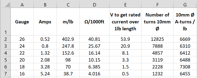
I'm trying to self-educate on electric powering of a motor. The spreadsheet below is using data accumulated from:
Basically, this spreadsheet calculates the recommended:
  1. current for a certain wire gauge
  2. how long 1 pound of wire is
  3. How much voltage is needed to create the rated current (1) over the length (2)
  4. The number of turns over an arbitrary 10mm diameter tube for the length (2)
  5. And finally, the Amp-Turns of the 1-4 configuration for each gauge.
Basically, this last column is coming out with approximately the same Amp-Turns number within 14% of each other. And I think this number is only that different based on the approximations from those websites. There is no trend of finer versus courser being better. I take this to mean the "motor" would have the same power???

My question is: If I don't have any constraints to fitting the windings on the tube, what else is a consideration for picking the wire gauge?

Thank you for your help.
1687962338983.png
 
Last edited:

quorneng

Master member
Inq
DC electric motor design is quite complex. Remember is has three elements. The copper, the iron and the magnets.
Although a motor is relatively efficient at converting electricity into mechanical energy there are losses which create heat. An electric motor is quite densely packed internally so at high power you do have to consider cooling.
To make matters worse all three elements get less efficient as the temperature rises so creating even more heat and less mechanical power for the same electrical input.
A motor is fundamentally controlled by the ampere turns in the armature so in theory for an identical physical layout many turns of finer wire with less amperes can produce the same magnetic force as fewer turns of thicker wire with more amps. In reality it does not quite work like that as the way the wire can be wound around the iron core favours finer wire but heat dissipation does not.
Indeed over heating can become the limiting factor to the power generated as many RC planes with high power brushless motors have found.

The actual layout of a motor is a compromise between several conflicting attributes. There is no single 'best' solution but there may be one that best suits a particular use, even more so when you consider the complex aerodynamics a RC plane and its propeller.

Only in a very specialised application are you likely to be able to improve on a commercial motor design so it tends to be better to understand the attributes of a motor specification and how they might benefit the intended application.

just my own observations from experience.
 
  • Like
Reactions: Inq

Inq

Elite member
@quorneng, et al,

Thank you for replying. Let me re-iterate and add to my lack of constraints and re-word my question. For the moment, let us not assume I am designing a motor. I am merely talking about electric wiring wound to create electric motive force. For illustration purposes, imagine the school-age experiment of wire wrapped around a nail and hooked to a battery. There is plenty of access around this to cool it with air or water. There is no cyclic or alternating current.

If you understand that Electromotive force is constant with respect to wire gauge, you can skip over this:
If I were to take 1kg of copper to make wire for winding, the volume is a constant. From volume of a cylinder (Volume = Area * Length) we know Length is inversely proportional to Area. Thus, if I half the area, I get twice the length.

One post I found recommended not to exceed 4 amps/sq-mm. I assume this was a rule-of-thumb not to exceed for heat reasons. Even so, for now, I'll take this as a given even though (from above) I can cool it. Because one wire is half the area of the other, it can only carry half the current.

One equation I found says (Electric Motive Force = Number of Winds * Amps). The number of winds is based on the length of wire. Because the wire that is half the area is twice as long, it gets twice the turns.

All this summarizes that the cross sectional area of the wire doesn't matter. The electric motive force is the same no matter what the wire size chosen. In other words, from what I have so far, there is nothing leading me to choose one wire size versus another. I am looking for clarity in that decision.


This simplistic geometry viewpoint is directly contrary to what I see in practical design of brushless motors. They can have different diameter wires and thus get different KV ratings. Maybe brushless motor design is different because of alternating current and I'd need to dive deeper into Physics and Inductance to explain them. However, in my case... inductance is zero because it uses DC current, so brushless design may not be an analogy worth considering.

So I'm back to asking... What other design decisions might influence a choice is wire gauge to making an electromagnet?
 

Piotrsko

Master member
Inductive force is proportional to watts either AC or DC. AC for this purpose is just DC reversing itself with a null period having no current and max average current being about 1/2 square root of 2 and lagging max voltage. However high frequency has it's own unique set of losses and conditions.

Wire gauge suggests a maximum gauss possible like @quorneng said about ampre turns. There are coil calculation formula on the web

Winding configuration may result in a concentration of gauss at some point as well as wiring form materials
All the major auto people are going to induction with "moving" induced fields in the rotor. But beyond my pay grade.