wing loading, span, flying speed, landing speed, charts.

OwenN

Active member
As I have discussed in the motor rating thread, my latest plan is:
34 inch span, 56 oz/sq ft, 2.2 lbs, 91 sq inches.
I want to know its good cruising speed , landing speed, and suitability for aerobatics. At launch , thrust to weight is about 4:1
I expect it to max out at around 60 mph, but I haven't done the latest drag, thrust, pitch speed calculations yet.
I want aerobatic speed to be around 40 mph.
Do you have example tables for this size aircraft? I can only find info on 100 inch warbirds, that weigh 33 lbs, and they generally fly much faster.
Also, wing loading is not directly comparable over such a large difference in span.
I am starting a new thread, as the topic has changed a bit.
 

OwenN

Active member
Assuming a lift coefficient of 0.7, this wing will stop lifting at 45 mph, given area and weight.
Thus useful flight speed will be somewhat above this. Also, delta-style wingd generally have a lower lift coefficient.
also, this coefficient is only good for low reynolds range around 17 mph. - what is a better estimate of lift coefficient?
 

PsyBorg

Wake up! Time to fly!
Number soup is not very helpful for what you are asking..

What type of plane are you designing? high wing trainer? warbird? your own custom design.. what type fuselage. too many unknows to even begin to form an idea to aid you. Start at the basics then nerd out with the maths.
 

OwenN

Active member
reworking speed/pitch speed, drag gives an estimated top speed of 90 mph., so 70 % cruize is 63 mph.
this give a good margin over 45 mph stall, but any loops or banked turns will be quite large at 63 mph. also , time to cover 300 mt-visible range, is only 10 seconds across the range circle. - easier to follow than a pylon racer, I suppose, at 3 times the speed.
 

OwenN

Active member
A loop pulling 10 G is 156 m in diameter at 63 mph. Find stall speed for 10x weight.
This is now 141 mph, so it cannot pull 10 G.
(3x stall speed)
can actually pull 2 G from the lift equation.
V = sqrt(2 L/ density x wing area x lift coefficient)
L = weight (N in si units)
This gives a loop radius of 392 meters, which is a bit big! so not very much a stunt flyer. You would have to be able to pull massive rotation rates and scrub off lots of speed to get around at all. It may actually have that sort of control authority, and enough power to just fly out of a stall without losing control. The canard and wing prop wash would help there.
It should not be able to orbit within a 300 m circle, which a pylon racer does just fine! mind you, its flight speed is well in excess of its stall speed. it must be pulling 20 gs plus on turns.?? does my calculation logic sound correct?
from the video, the pylon racer seemed to be doing 50m turns at 200 mph (30,000 rpm) From a = w(sq) x r, V = wr
means g = 324, which seems very high.... - I would have only put it at 20 g at the most.
It probably slows a lot in the turns. It seemed to be covering about a 250 m loop in about 5 seconds - that would be an average of 112 mph.
- enough to make you dizzy!
Their speed estimate must be off . Mind you, a 7x6 inch prop at 30,000 rpm has a pitch speed of 171 mph.
The pitch would have to be 8 inches per rev at least. to get into the speed-drag range for 200 mph.
 
Last edited:

OwenN

Active member
Number soup is not very helpful for what you are asking..

What type of plane are you designing? high wing trainer? warbird? your own custom design.. what type fuselage. too many unknows to even begin to form an idea to aid you. Start at the basics then nerd out with the maths.

Wing area, weight ,configuration, and speed range give enough info to work out a probable stall speed, or at least the point where flying becomes rather soggy. I think my slow flight prediction of 45 mph is not far off. This design will go slower, but it is well into landing approach -type behavior then.
I have stated somewhere that it is a delta-canard, similar to the saab viggen layout, but with props between the wings.

I think to manoeuver in a 150m circle, at a starting speed of 60 mph, it will have to be really slung about, stall, then fly out of stall. It should do that, but will look a bit ungainly. having a massive thrust reserve helps.
 

Hondo76251

Legendary member
@PsyBorg its not soup, its a 7 course meal! 🤣🤣

@OwenN some people really like numbers, i can see that must be your thing. Nothing wrong with that but model planes, while obviously subject to the rules of physics, are almost equally ruled by Murphy's law and things will rarely work out as squeaky clean as those numbers.

The two biggest variables here are the pilot and the builder!
 

OwenN

Active member
1) I found a bit of extra area in this platform, so wing loading is down by 5.5 %. by scaling up from 34 to 36 inch , that would drop loading another 12%. starting at 55 oz/sq ft , it could go down to 46.4 oz/sq ft. (8.6 %) this lowers stall speed by about 3%, from 45 mph to 43.5 mph.
I think I will stay with the 52 oz/sq ft.

2) Strength : I don't think this will be a problem, with fully sheeted construction, and plenty of web-spars.
I have built a few flying model planes, and have mechanical engineering training, as you can probably tell.
Loading of actuators may be an issue-I will be using 6 volts and 2.2 kg/cm.

3) Predicted vs actual flying behavior: this platform, with the prop blow-over effect, and massive thrust, should be un-stallable to any significant extent-it will just hang from the props. - it may, however get pointed in odd directions, so major radical stunts should be done
50 + meters up or higher. If pointing down, go to 120 m (400 ft) and start there.

4) Skill : this has all the flash quad-copter nannies, plus some more ardupilot ones, so shouldn't be any harder to fly. After a few hours,
those things get fairly easy.( for non-stunt or race use, anyway).
Lots of altitude is the key, here. It should be almost self-landing, in STOL or VTOL mode.

I do need lots of practice- I shall run the simulators heaps before getting out there. I haven't done RC airplanes before, so I expect a few
crashes. Hopefully not the sort that totally writes off the airframe, and destroys all onboard components.
An airframe can be rebuilt fairly quickly-it is just lots of balsa construction, after all.
 

OwenN

Active member
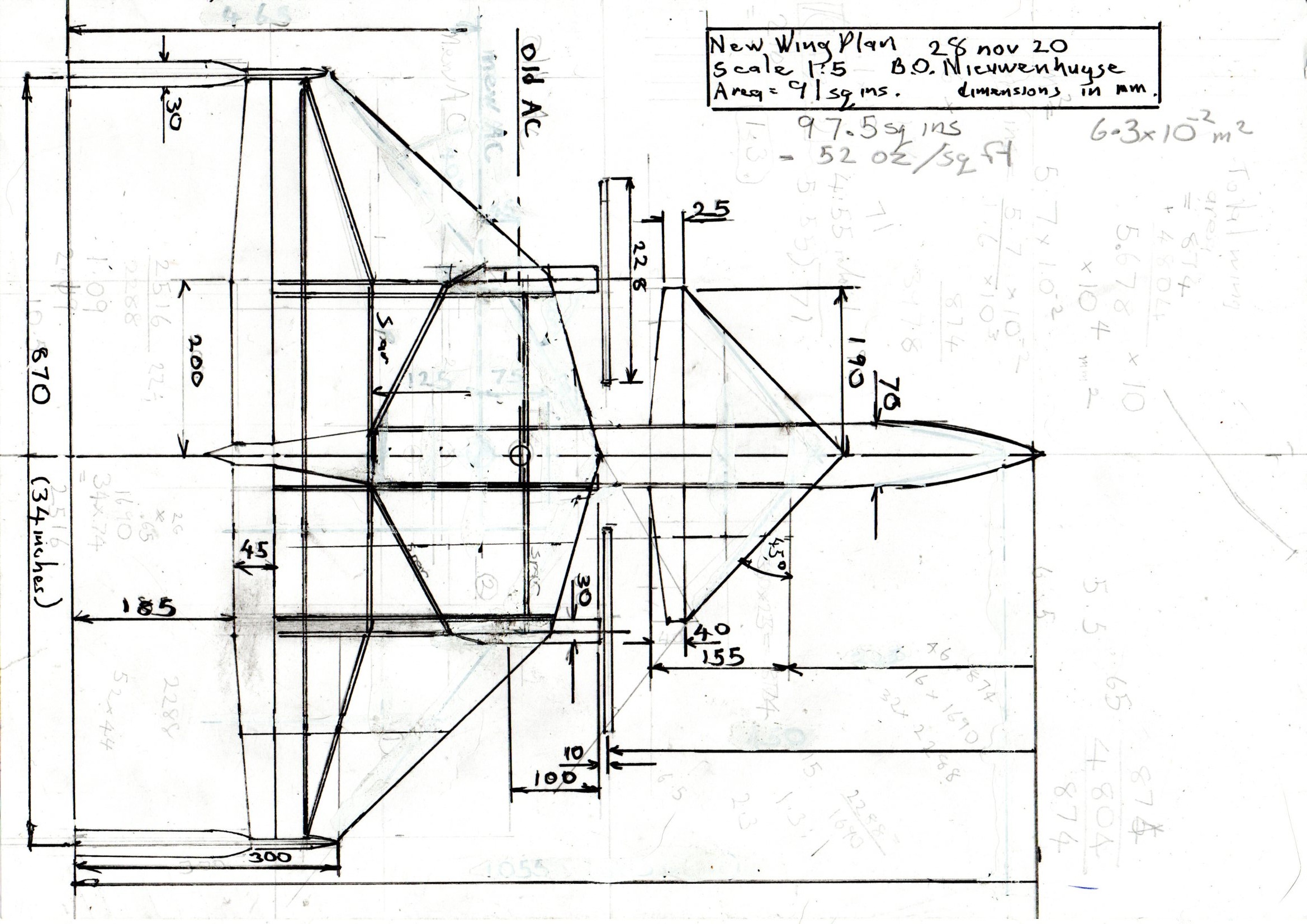
This is the latest small scale wing plan view. I am working on the full size one. the main web spar unit is 6mm further towards the nose.
More radial webs and center ribs to be added. The front outlined inner wing section is hollow-good for poking actuators in there, so I can use 2 laying flat with the arms together. The fuselage was extended another 2 inches, I haven't added the new dimensions back.
wing plan 30 nov 20.jpg
 

quorneng

Master member
I would suggest that wing lift coefficients tend not to mean much for smaller models as the actual aerodynamic performance is more limited by the drag of the rest of airframe largely due to skin friction. At small sizes air is relatively viscous, think like trying to fly through treacle.
The shape, surface area and finish of the rest of the airframe are likely to have a bigger effect on performance than the actual lifting surface and of course the power requirement to fly rise rapidly (by the square?) of the speed. ;)
 

OwenN

Active member
I see that E-calc suggests a surface-Cd of 0.05 as opposed to 0.03 for most full size aircraft. - there is the skin friction factor.
If you sub this into D = 2 x density x (V squared) x wing area x Cd then it should get the thrust needed at a particular speed.
I take the pitch speed, guess at a speed reduction for drag, work out the drag=thrust for this speed, and try again until the numbers
match up. - this should be close to the actual top speed.
where thrust V = sqrt( T/ 2 x density x prop swept area) or T = (2 x (Vsq) x prop swept area), T = D

Here is a similar wing platform, but I have eliminated the built-in canard angle of attack and made the wing sections thicker.
If you are going to control it anyway, and have gyro levelling, then any extra trim angle gets in the way. I don't think negative dihedral
is needed, but I shall see. This removes some self-corrective roll levelling, and also may counteract "dutch roll" tendency, where you get anti-roll and yaw oscillations. deltas tend to roll-correct without dihedral.
My concept has less ribs and spars, is fully sheeted, and uses egg-crate type wing stiffening and thicker section, with more taper.
That small area of wing left unsheeted doesn't save much weight..
vig 2.jpg
i
vig 1.jpg
 

OwenN

Active member
Updated wing plan. Added: extra radial spar webs, extra ribs, spreader plates from load points into skin,
Detail on ply tie piece for forward spar web.
Note: if a full 1/32 balsa skin is used, less ribs are needed, and the wing is no heavier than the example of the Saab Viggen model(for a similar area), but much stiffer.
The skin also acts as part of the spars, spaced out by a 1/16 balsa egg-crate wing spreader, also acting as part of the spars.
The degree of taper, and having a wing root depth of about 40mm, assists stiffness and strength.

Normally this degree of taper negatively affects the lift coefficient, but the flow from the outward-turning props (viewed from the top)
counteracts any negative effects-see the "flying flapjack", Chance Vought V -173.
The thicker wings may have a negative effect on the drag coefficient, as well, but this is more significant at higher speeds and larger scales.
wing plan 1-dec-20.jpg
 

Tench745

Master member
This is a lot to wade through. Most people here have little experience with calculations like this, myself included, though I think I may have a little more experience than most.
Some quick thoughts:
When comparing wing loadings and flight characteristics of widely disproportionate sized models cubic wing loading can be useful as it scales correctly.
I notice you're not using Reynolds numbers, which take into account size, speed, and fluid viscosity.

A CL of .7 sounds low to me, but I don't know what airfoil or Reynolds number it is for.

For model aircraft specific calculations I'd direct you to the book Basics of RC Model Aircraft Design by Andy Lennon. I learned almost all the aero-maths I know from this book, so if it's not in there you've exhausted my knowledge. You'll probably understand it better than I do since I do not have your engineering background.

Edited to add:
If you're hoping to compare to different sized aircraft of similar configurations or characteristics, the concept of Dynamic Similitude can be brought into play as well. With the right formulae the same conclusions can be reached, but the way you were talking, this seemed like it might have some passing usefulness to you.
https://www.mnbigbirds.com/Scale Factors Page.htm
https://www.scaleaero.com/maneuver_realism_speed.htm
 
Last edited:

OwenN

Active member
Thank you. I found a PDF online for that, so I will read it through. I didn't go back to the reynolds number, as the thesis (on a cheap combat RC model) used so many fudge factors to go from 2d factor to 3d factor, I needed another source. Also his factor was for 17 mph, mine should be for around 45 mph- does chord length come into it too?-sounds vaguely familiar...
I will check the others out too.
 

OwenN

Active member
Had a look - I don't like the standard airfoils that much. I will redesign mine, however. how about 13 degree rear taper, drop the nose curve down and shorten the front under-curve , flat underneath, 11-13 % height to chord, maximum height about 1/3 back from the leading edge.
Effectively undercambered, and the no-lift line running above the nose curve. - What do you think? This is in no way aerobatic, but should fly inverted, loop, barrel roll, hammerhead, no full spin or snap-roll, but short-balanced and high control response, so it can do some things most aerobatic models can't- flat propeller-spin,(similar to falling leaf) wing-down corkscrew dive?? - the gyro stabilisation will help push it right to the edge of aerodynamic balance, and keep it controllable.
 

OwenN

Active member
New foil shape:
9.7% height to chord, nose up 10 mm, nose radius 5 mm, top lead-in angle = 24%, tail angle =14%,
slightly reflex into rear elevon at 6 mm x 45 mm, tapered. As always, 25.4 mm = 1 inch.

This section chord is 360 x 35 high.
The highest point is at 33% in, though the middle 50mm is pretty close to flat.- only 0.5 mm deviation both ends.

I will check out the tip thickness, slope along the wing, and the other two main sections later: Tip and Root.

THe main change is an increase in centerline camber, and dropping the nose profile down from 15mm up to 10 mm up.
 

OwenN

Active member
No, that didn't look right. -flattened the tail down to 12 degrees, nose now asymmetric, with a greater curve on top, sharper nose, and furthest projection now down to 7mm up from the flat base. Is there a way of predicting how a random airfoil shape will fit in to the more standard ones? -- I will continue reading Lennon.