floz
New member
I'm sure this has been done before. I know quadcopters and LEDs go well together...
But us fixed-wing fans can have just as much fun and do it without adding a ton of weight to the aircraft.
Most everyone has seen the LED strips to the left, where you send a data signal down the line and they daisy-chain, creating multicolored patterns. These are great, and work perfectly well in most dtfb builds.


The tiny 'chip' to the right is the same thing, without the bulk of the strip. Instead, they have six contacts on the back side for 5v in/out, Data in/out, and Ground in/out. Using these, we don't have to run a long strip of LEDs through the wing if we only want wingtip lights, instead we can just use long'ish wire and place our LEDs where we want them.
I'm not endorsing amazon, but here's an example link of one place to find the chip form-factor ones: https://www.amazon.com/dp/B00P2GQUYC/?tag=lstir-20
To control these magic-pixie light shows, we need some sort of logic. Thanks to the hobby electronics explosion of the last several decades, we have the Arduino ecosystem to choose from.
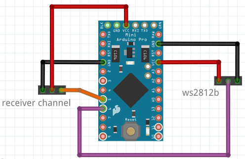
They require 5v, DATA, and Ground lines be connected in a daisy-chain, as shown here.
~1.75g control board, but this model is not USB-programmable without the added FTDI board.

They're then addressed in software by their ID#, for example:
leds.setPixelColor(0, 255,255,210); //bright warm white
leds.setPixelColor(1, 255,255,255); //bright cool white
leds.setPixelColor(2, 255,0,255); //bright purple, because why not
leds.setPixelColor(3, 0,255,0); //bright green
...and so on.
Each dissipates about 0.5W of energy at full bright white (255,255,255 :: red,green,blue), nearly all of it in light.
They rarely get warm unless you make panels out of them or something.
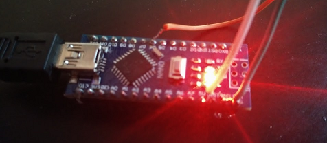
The controller board seen here is 1 and 5/8 inches by 5/8 of an inch and weighs about 2.5 grams without the pin headers. Bonus, it's USB programmable.

For my first try (in the Cub's 4ch wing), I chopped up an old rather long IDE (old school computer hard drive) ribbon cable, wired it all up, and simply had the software on the controller board running nav lights continuously. At this point, it's powered by the BEC/receiver similarly to how a servo would be.

Once I saw how well this hack-job was going, I continued further with it and now have controllable lights from my radio.

Since it's kind of a pain to remove the wing after setting this up, I gave the problem some thought and designed a break-out-board for the purpose:
Attached is the Gerber and Fritzing export for the clean and tidy piggyback board. The three-pin headers connect to NP (neopixel LEDs) and PWM (radio receiver channel)
https://oshpark.com/uploads/bJIgMnDg OSHpark has it ready to order, too
Various Arduino nano and mini boards should fit atop it, including some of the usb-programmable nano boards. I know the following boards should fit/work with this break-out-board and hobby RC gear:
Nano 5v Arduino/clone (16mHz atmega328p)
Pro-Mini 5v Arduino/clone (16mHz atmega328p)
I have tinkered around with the 3.3v 8mHz boards, but I don't know that I would trust them in a 5v system (hobby rc) with relatively unclean power.
Note: I have not yet ordered these boards from OSHpark, they may have errors, please check before you order!
The code for what I've got flying on it is at
https://pastebin.com/myuWP8ix v1
https://pastebin.com/7p0ArXpv v1u1
If you're not inclined to sort through my horrible code to figure out what it does, here's a brief rundown:
The arduino keeps the lights in one of three states depending on what instruction it gets from ch6 on the receiver:
1. Nav lighting (red/green with quick white strobe every 3.75 seconds)
2. Landing lights (bright, warm white with no strobe).
3. Battery Warning (10 minute run timer) alternating yellow strobe, regardless of which mode.
The arduino also listens to the radio receiver's output for servos (ch6 in my case) and depending on that channel's PWM value, determines what mode it goes into. You can modify the software to make all sorts of nifty lighting patterns, and re-burn it to any atmega328p "arduino" board. These little half-watt LEDs are actually bright enough that dtfb becomes a diffuser more than anything.
Of note: if you use more than two or three individual LEDs, you should probably check the current draw at full bright white before powering it from the receiver. Wouldn't it be awful to kick on landing lights and brown-out (or worse, blow-up) your receiver? Still, for two or three of these LEDs, it's been fine so far in my experience.
EDIT: A thought just occurred to me... for warbirds, you could totally use this for muzzle-flash on your wing-mounted machine guns. Updated code some, optimizations all over it.
Happy flying,
Floz
But us fixed-wing fans can have just as much fun and do it without adding a ton of weight to the aircraft.
Most everyone has seen the LED strips to the left, where you send a data signal down the line and they daisy-chain, creating multicolored patterns. These are great, and work perfectly well in most dtfb builds.


The tiny 'chip' to the right is the same thing, without the bulk of the strip. Instead, they have six contacts on the back side for 5v in/out, Data in/out, and Ground in/out. Using these, we don't have to run a long strip of LEDs through the wing if we only want wingtip lights, instead we can just use long'ish wire and place our LEDs where we want them.
I'm not endorsing amazon, but here's an example link of one place to find the chip form-factor ones: https://www.amazon.com/dp/B00P2GQUYC/?tag=lstir-20
To control these magic-pixie light shows, we need some sort of logic. Thanks to the hobby electronics explosion of the last several decades, we have the Arduino ecosystem to choose from.
They require 5v, DATA, and Ground lines be connected in a daisy-chain, as shown here.
~1.75g control board, but this model is not USB-programmable without the added FTDI board.

They're then addressed in software by their ID#, for example:
leds.setPixelColor(0, 255,255,210); //bright warm white
leds.setPixelColor(1, 255,255,255); //bright cool white
leds.setPixelColor(2, 255,0,255); //bright purple, because why not
leds.setPixelColor(3, 0,255,0); //bright green
...and so on.
Each dissipates about 0.5W of energy at full bright white (255,255,255 :: red,green,blue), nearly all of it in light.
They rarely get warm unless you make panels out of them or something.
The controller board seen here is 1 and 5/8 inches by 5/8 of an inch and weighs about 2.5 grams without the pin headers. Bonus, it's USB programmable.

For my first try (in the Cub's 4ch wing), I chopped up an old rather long IDE (old school computer hard drive) ribbon cable, wired it all up, and simply had the software on the controller board running nav lights continuously. At this point, it's powered by the BEC/receiver similarly to how a servo would be.

Once I saw how well this hack-job was going, I continued further with it and now have controllable lights from my radio.

Since it's kind of a pain to remove the wing after setting this up, I gave the problem some thought and designed a break-out-board for the purpose:
Attached is the Gerber and Fritzing export for the clean and tidy piggyback board. The three-pin headers connect to NP (neopixel LEDs) and PWM (radio receiver channel)
https://oshpark.com/uploads/bJIgMnDg OSHpark has it ready to order, too
Various Arduino nano and mini boards should fit atop it, including some of the usb-programmable nano boards. I know the following boards should fit/work with this break-out-board and hobby RC gear:
Nano 5v Arduino/clone (16mHz atmega328p)
Pro-Mini 5v Arduino/clone (16mHz atmega328p)
I have tinkered around with the 3.3v 8mHz boards, but I don't know that I would trust them in a 5v system (hobby rc) with relatively unclean power.
Note: I have not yet ordered these boards from OSHpark, they may have errors, please check before you order!
The code for what I've got flying on it is at
https://pastebin.com/myuWP8ix v1
https://pastebin.com/7p0ArXpv v1u1
If you're not inclined to sort through my horrible code to figure out what it does, here's a brief rundown:
The arduino keeps the lights in one of three states depending on what instruction it gets from ch6 on the receiver:
1. Nav lighting (red/green with quick white strobe every 3.75 seconds)
2. Landing lights (bright, warm white with no strobe).
3. Battery Warning (10 minute run timer) alternating yellow strobe, regardless of which mode.
The arduino also listens to the radio receiver's output for servos (ch6 in my case) and depending on that channel's PWM value, determines what mode it goes into. You can modify the software to make all sorts of nifty lighting patterns, and re-burn it to any atmega328p "arduino" board. These little half-watt LEDs are actually bright enough that dtfb becomes a diffuser more than anything.
Of note: if you use more than two or three individual LEDs, you should probably check the current draw at full bright white before powering it from the receiver. Wouldn't it be awful to kick on landing lights and brown-out (or worse, blow-up) your receiver? Still, for two or three of these LEDs, it's been fine so far in my experience.
EDIT: A thought just occurred to me... for warbirds, you could totally use this for muzzle-flash on your wing-mounted machine guns. Updated code some, optimizations all over it.
Happy flying,
Floz
Attachments
Last edited:


