1:1 scale Mars Ingenuity Helicopter

NickRehm

Member
Got absolutely ransacked by exams/assignments the past two weeks, but I finally found some time to finish up the CAD (added upper fixed pitch rotor, and other small updates). Parts are slowly but surely coming off the printer still--I'm trying out PETG and its taking some time to dial it all in.

The motors I ordered are finally in after 4 weeks too. I think the next giant leap in this project is committing to some of the shaft lengths in CAD and heading into the workshop to cut them all down to size. Then I'll need to spend a bit (a lot) of time dealing with bearing and shaft tolerances being not quite up to spec. Then I'll focus on blades....I've got some root inserts, 5mm carbon shafts, and I'll sand them down to shape before maybe covering them with something (tape? would be a lot easier than a layer of fiberglass)
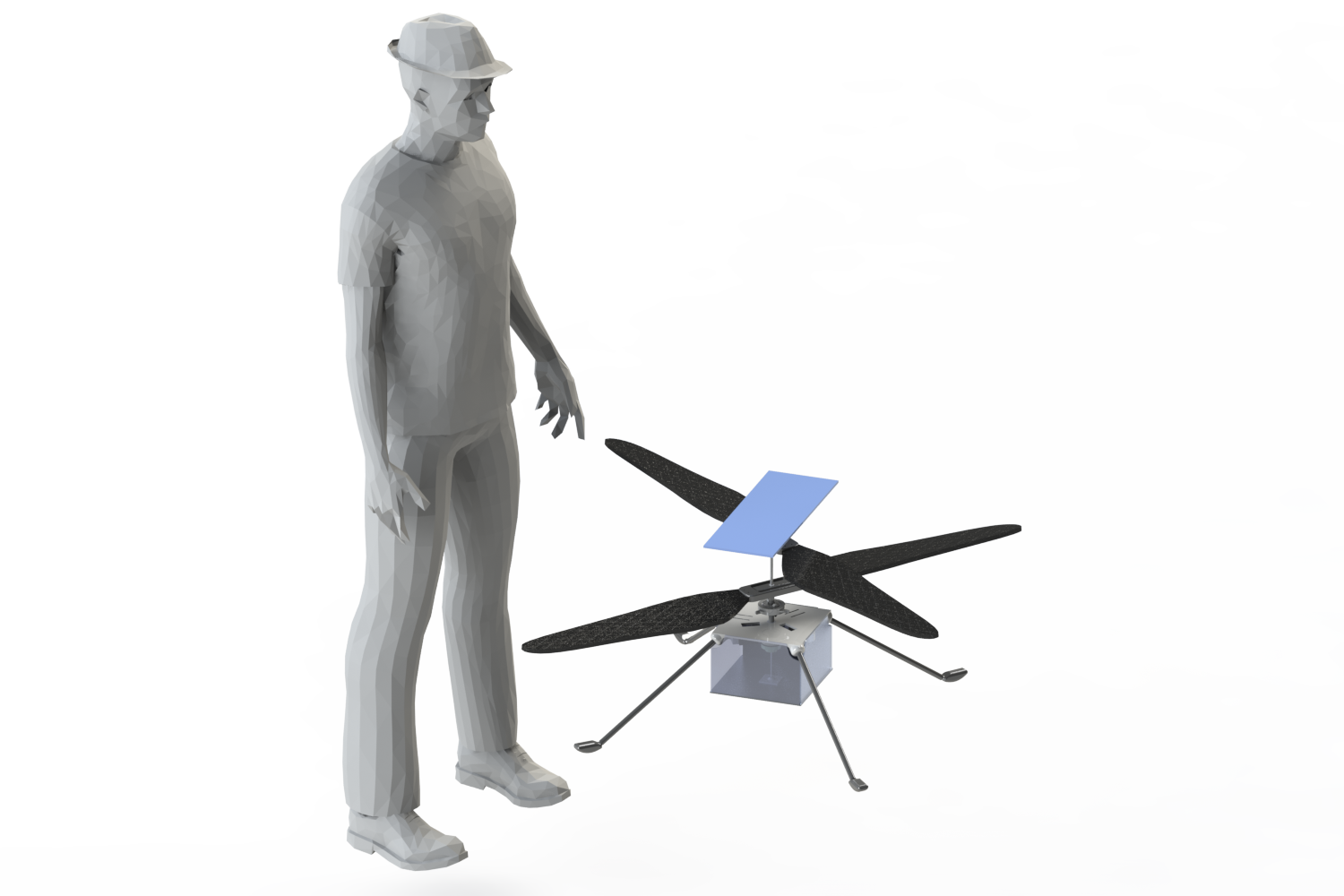
full render 4.2.21.png
 

NickRehm

Member
Got to the shop to cut some shafts and size them up for my bearings. Skeleton is taking shape :) Next up is motors installation and testing the drivetrain before securing parts (epoxy) to the shafts... Then blades...then electronics. Stay tuned
IMG_5414.JPG
IMG_5415.JPG
 

Pilotr2020

Member
This is AWESOME!!! However, don't use the airfoil of the original, because it was made for lower atmospheric density. Other than that, this should work great.
 

NickRehm

Member
This is AWESOME!!! However, don't use the airfoil of the original, because it was made for lower atmospheric density. Other than that, this should work great.
Thinking of just going flat plate on the blades, since there's so much extra chord compared to typical 'Earth blades'. It'll be very inefficient, but I shouldn't need very high head speed for sufficient lift in Earth atmosphere, so profile drag won't dominate as much
 

NickRehm

Member
Main fuselage mounting plate loaded up with servos, motors, and pulleys:
IMG_5430.JPG


Accidentally broke part of the swashplate assembly so a few more parts need to be printed overnight. Hopefully I can finish the linkages and get the lower rotor actuating cleanly tomorrow, then I'll work on electronics so I can spin it up to check if the belt tension is good or not. I'll also carefully be checking current on these 500kv motors--geared down 4:1(???) I think--to make sure I don't burn them out. Overall the shaft/bearing fits are B+ at best, but clean enough I think to work. My biggest concern now is controllability and the foam blades. I've been inspired by Ran D's 'Spin TOL' which is what I'm trying to somewhat replicate with this whole 'scratchbuilt' heli route:
 

NickRehm

Member
Hopefully we see a flight (of the real Ingenuity) tomorrow morning! I spent some time tonight getting the swashplate all setup and the 'blade grips' mounted to the main shafts. When I can find the time, the next step is hooking up electronics to see the proper swashplate actuation while the blades are rotating, and to make sure there's not too much resistance on the geared down motors. It feels fairly easy to rotate by hand, so fingers crossed it stays that way...

Start placing bets on if this thing really flies or not. I'm giving it 40% chance of success at this point

image1 (1).jpeg

image0 (1).jpeg
 

NickRehm

Member
It's been a while since the last update, because I got swamped with final exams and projects.... But I FINALLY found some time today to get cracking at finishing this build up. Pics attached.
IMG_5677.JPG


The fuselage is just foamboard hot glued to the main fuselage mounting plate. I've got my flight controller buried in there along with some 30a ESCs, 10a BEC for the huge servos, and a 1500mah 4s battery. The blades aren't done yet, but I was so excited to see this thing fully assembled. They still need beveling, taping, and balancing.

IMG_5681.JPG


Next up is taking care of the blades, then other small issues like belt tension, then we'll try for a flight. Even if it doesn't work, I think I'm still going to give it a really nice paint job. Super cool having a 1:1 scale Ingenuity sitting in the living room :cool:
I think I'll call this one "Scrappy", Ingenuity's little brother
 

Attachments

  • IMG_5678.JPG
    IMG_5678.JPG
    3.4 MB · Views: 0

Phin G

Elite member
It's been a while since the last update, because I got swamped with final exams and projects.... But I FINALLY found some time today to get cracking at finishing this build up. Pics attached.
View attachment 200765

The fuselage is just foamboard hot glued to the main fuselage mounting plate. I've got my flight controller buried in there along with some 30a ESCs, 10a BEC for the huge servos, and a 1500mah 4s battery. The blades aren't done yet, but I was so excited to see this thing fully assembled. They still need beveling, taping, and balancing.

View attachment 200763

Next up is taking care of the blades, then other small issues like belt tension, then we'll try for a flight. Even if it doesn't work, I think I'm still going to give it a really nice paint job. Super cool having a 1:1 scale Ingenuity sitting in the living room :cool:
I think I'll call this one "Scrappy", Ingenuity's little brother
Plans?!? ;)
 

NickRehm

Member
Need some advice/thoughts: having some trouble getting the required belt tension to prevent slipping. Right now, I can hit about 30% throttle before both upper and lower belts start to slip, quite badly. I'm thinking this wasn't the right application for belts with such high required torque... I know torque will reduce once I shape and balance the blades properly, but I know it won't be enough. I'll keep trying to get the tension high enough, but would appreciate any thoughts

On the bright side, I did spool up to about 25% throttle and actuated the swashplate and felt the proper control moments--so that works! That was my biggest concern of this whole build actually, so if we can get this belt slipping issue figured out, I am certain I can stabilize this thing in a hover with my flight controller
 

JasonK

Participation Award Recipient
if I was to make a guess from your photos, your motors (and possible the center shafts) are mounted in a way that leaves them flexable. Which the torque gets applied, it flexes the parts enough to cause the belts to slip. Stabilizing both ends of the shaft (with bearing) relative to each other should reduce/eliminate the flexing of the shafts that is letting the belt go loose. (and if done right, will allow the belt to be taunter without puting stress on the motor shaft inside the motor)
 

NickRehm

Member
if I was to make a guess from your photos, your motors (and possible the center shafts) are mounted in a way that leaves them flexable. Which the torque gets applied, it flexes the parts enough to cause the belts to slip. Stabilizing both ends of the shaft (with bearing) relative to each other should reduce/eliminate the flexing of the shafts that is letting the belt go loose. (and if done right, will allow the belt to be taunter without puting stress on the motor shaft inside the motor)

You are probably right... Little bit of play in the motor mounting/main shaft even after giving them plenty of reinforcement/mounting points. Considering moving over to gears as a quick fix.

New question: anybody have experience 3D printing gears? Anything I should be aware of in terms of strength or tolerances?
 

JasonK

Participation Award Recipient
You are probably right... Little bit of play in the motor mounting/main shaft even after giving them plenty of reinforcement/mounting points. Considering moving over to gears as a quick fix.

New question: anybody have experience 3D printing gears? Anything I should be aware of in terms of strength or tolerances?
I have printed a few, tolerances depend on your printer/configuration/tune. Strength is going to depend on your material and printing setup.

I would suggest doing a test spin up of your 3D printed gears in a spot that is safe if they explode.

My use case was part of the tilt mechanism for a VTOL, not something that would be spinning as fast as your motors probably are going to be going.
 

NickRehm

Member
I have printed a few, tolerances depend on your printer/configuration/tune. Strength is going to depend on your material and printing setup.

I would suggest doing a test spin up of your 3D printed gears in a spot that is safe if they explode.

My use case was part of the tilt mechanism for a VTOL, not something that would be spinning as fast as your motors probably are going to be going.

I've got something on the printer now in PETG... Will definitely be very cautious with them haha. Appreciate the insight and heads up

Should have done this from the beginning....

Capture.PNG