Inq
Elite member
Edit: This tread originally started out asking about a request for centrifugal weight based variable speed propellers. After some initial CAD work, I realized swinging weights, and 3D printed ball bearings were just not going to fit inside the spinner of the desired 1/12th scale plane. As the thread progresses, I go back to the more complex, but smaller spinner packaging of a computer controlled servo pitch design.
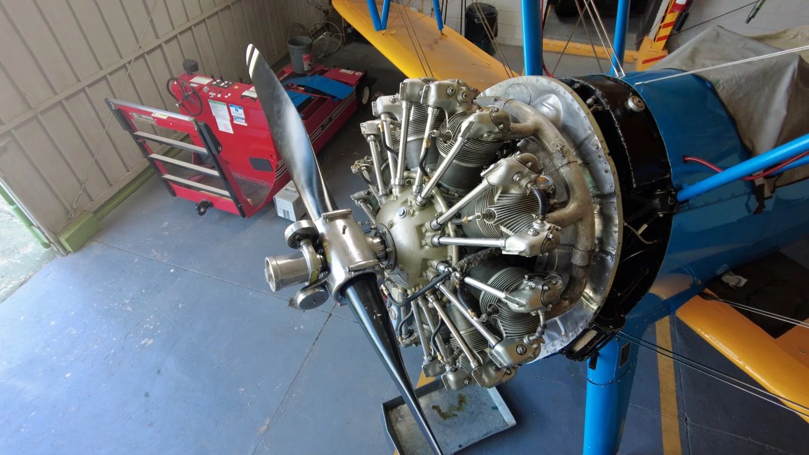
I've used various Google searches including the title that don't seem to find the hits I'm looking for. Invariably I get millions of hits for constant speed propellers using the hydraulic line through the drive shaft that came about around WW2 and is still used today. I'm looking for details on a propeller design that was used I believe around the 1930's. It used weights at the end of offset arms to twist the propeller blades as a function of rpm - as the rpm's climb, the centrifugal force would spin the weights out causing the blade to increase pitch, causing more drag and thus slowing down the rpms. Tuned just right, it would maintain a relatively constant RPM. Here is a picture of one on a Stearman...
I've taken a stab at the problem using first principles, but I'd really like to get a reality check from existing designs. I'm looking for anything that might be of a more "how to design" type article.
Background - I looked at the Constant Speed Propeller design from an electronic viewpoint - (1) getting either mechanical linkage through the turning shaft (swashplate, helicopter design) or (2) putting the servo in the spinner (power and control data to the servo through the spinning shaft). I went so far as to even look at wireless charging to power a Bluetooth/MPU unit to control/power the servo. It spiraled down to China. It just doesn't seem feasible at the 1/12th scale I'm attempting. So I've turned to 1930's tech to tackle the problem.
Any/all references, pointers, or comments are desired.
Thanks,
Inq
Last edited:

 I've never heard of 4D before. Definitely a couple of orders of magnitude above my skill level.