telnar1236
Elite member
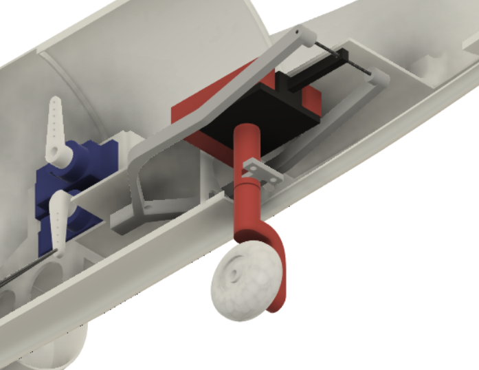
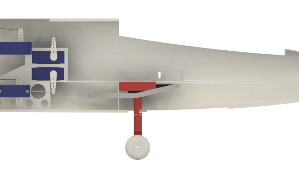
I designed the nose gear, nose gear mount, and nose retract control linkage over the last few days. Because I am using a mechanical retract, the top of the nose gear must be fixed, so the rotation point and control horn must be integrated into the strut further down which introduces complexity. In addition, because the retract is in front of the servo driving it, but also retracts forward, the control linkage for the servo has to reach around the retract.

The control horn on the nose gear is just a placeholder currently and would not work in its current configuration and the control rod from the 3d printed retract linkage to the servo is not modeled. Steering will be driven by a pull-pull connection to a bell crank which will be driven by the rudder servo, which avoids all the concerns about the steering linkage preventing retraction and the control horn on the retract unit moves inward when retracted so it won't interfere with the steering control horn.

Finally, I found some 30mm wheels and they fit better for the main gear. The nose gear wheel is 25mm and I may change out the main gear wheels to be the same.

The control horn on the nose gear is just a placeholder currently and would not work in its current configuration and the control rod from the 3d printed retract linkage to the servo is not modeled. Steering will be driven by a pull-pull connection to a bell crank which will be driven by the rudder servo, which avoids all the concerns about the steering linkage preventing retraction and the control horn on the retract unit moves inward when retracted so it won't interfere with the steering control horn.

Finally, I found some 30mm wheels and they fit better for the main gear. The nose gear wheel is 25mm and I may change out the main gear wheels to be the same.


