3D Printed 64mm MiG 21

telnar1236

Elite member
I automated leading edge flaps, but looking to do it by differential max high static pressure between upper and lower surfaces.

That sounds like a neat project. The immediate issue that comes to mind is that aerodynamics is nonlinear so even if you had an easy way to tell the LE flaps which way to go, you might just end up at a local maximum instead of an overall maximum for lift. I think the simplest way to go would be to gather a ton of data on the lift vs. angle of attack for your wing with multiple LE flap deflections and then use that data to generate a curve mapping LE flap deflection to angle of attack which you could then measure with either two pressure probes (which would require more data gathering) or more simply with the more conventional airfoil stuck to a rotary pot.


Played around with different techniques dealing with high alpha, stalls, and ducting with EDF's inlets as well as exhaust areas. Did testing to back it up. Interesting one was the SR-71 were I picked up good info on inlets and exits. Best project was trying to take a single 5 bladed EDF and bleeding off pressure to the end of the wing to counteract yaw so it will hover. Some success, watch the video.

Interested on your problems with stalls and ducting. You should see how I choked the EDF and it performed well.
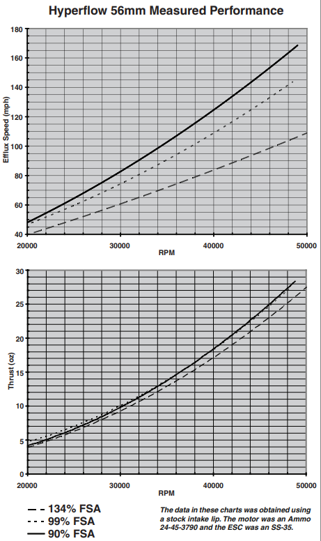
That's some great piloting of that F-22. I have noticed some EDFs are much more sensitive to inlet area than others. I had an old six blade 64mm from Hobbyking that ran on 3s and would outperform most of my 4s EDFs even with far too small of inlet/exhaust areas, but for most EDFs there is a notable difference. It's hard to find good data from the manufacturer but this is one of the few examples. It shows thrust and efflux speed vs. nozzle area and there is definitely a difference. It is also worth noting that efflux speed translates to thrust at speed so what might not be a huge deal at 10 or 20 mph is a big deal at 60 or 70 mph. Inlet area and inlet duct efficiency are even more critical.
1676686663275.png
 
Last edited:
  • Like
Reactions: Inq

telnar1236

Elite member
I'm not too worried about trashing it. I've embraced the F.T. concept of celebration when an accident happens. Gives me a chance design and build another plane. Maybe the same one, maybe a new one. :LOL:

But your video does suggest something. Instead of concern about having enough speed on launch to get usable control reactions... just "shoot" it up and completely rely on thrust until it gets up to speed.

I wanted to benchmark my EDF anyway so I can see how much ducting losses I might have and incrementally improve them. But it will give me an idea if I'll have a better than 1:1 trust to weight.

Outstanding piloting also didn't hurt!

On my first EDF build F-8... where piloting experience will be an issue. I'm concerned about having enough control authority at low speeds of landing... a belly lander. Have you considered putting say... elevon and rudder type surfaces at the trailing end of the exhaust tube? Vectored thrust kind of thing?
Vectored thrust is not a great idea on a trainer, but it can be very fun later on. For launching an EDF, especially a light-weight one, just give a good hard underhand toss slightly upward and it will fly away nicely, then wait to give control inputs until you have a bit of speed. You don't have a big prop so the torque is pretty negligible. I would guess your F-8 will be as easy to hand launch as some prop planes.


I'm not too worried about trashing it. I've embraced the F.T. concept of celebration when an accident happens. Gives me a chance design and build another plane. Maybe the same one, maybe a new one. :LOL:

But your video does suggest something. Instead of concern about having enough speed on launch to get usable control reactions... just "shoot" it up and completely rely on thrust until it gets up to speed.

I wanted to benchmark my EDF anyway so I can see how much ducting losses I might have and incrementally improve them. But it will give me an idea if I'll have a better than 1:1 trust to weight.
Vertical launching can work, but you need a much better than 1 TWR since you need to gain speed quickly enough that the plane doesn't lose control if you don't have thrust vectoring. You also need the thrust line to be through the CG or the plane will just flop over if it doesn't have enough speed for the control surfaces to work. I would guess a normal hand launch would be the easiest method, or a dolly for ROG takeoff if you have somewhere smooth to fly off of.
 

telnar1236

Elite member
Could you share the way you perform the calculation?


I'm going to assume conservatively since you mentioned the F-8 tends to be bad handling. I'll go 10% of my A.C. chord line... unless your calculation method incorporates some factors for tip losses Reynolds number differences.
As far as I can tell, the only difference is that I just use the formula for the y centroid of a trapezoid. I'm embarrassed to say that it took me a good 20 or 30 minutes to figure out that you had just split your shape into a parallelogram and triangle for the centroid calculation. I'm so used to just creating a 25% chord line and then finding the intersection with the y coordinate of the centroid that I kept thinking that your division was some strange way of doing that.
1676685937329.png

10% MAC is probably a pretty safe place for a starting CG. It should definitely fly with that and you can shift it around as you start to play with getting the plane dialed.
 
Last edited:
  • Like
Reactions: Inq

telnar1236

Elite member
My video suggest two things:
1) Pick airplanes that are designed light and can handle stresses. Hence vertical takeoffs, dual landings and are very stable .
2) Too see if you have enough thrust and ducting losses, take the plane ready to go, hold vertically, add power until it hovers. My rule of thumb is if throttle is 1/2, go chuck it. If it takes 2/3 to 3/4 throttle, put landing gear and you need to be a good pilot to get it up and down.
3) If you are close to 1/1 ratio, you can chuck it and nurse it into flight, if you throw too steep, roll over is the result.

There are very little ducting losses for what we do. That is including ducting in the front. Only problem is if inlet area is smaller than fan duct area, yes it happen, can use cheater area under the ducting. Used pitot system to verify. This duct is over 12".


View attachment 235112
You can definitely fly with a lower thrust to weight ratio than that. You just need a much less draggy plane. It is rare for one of my designs to have a thrust to weight ratio over 1. You just need to fly the wing. Ducting losses also come into play more at speed. A plane with open but inefficient ducting might have a great TWR at low speeds but lose it very quickly as it gets faster where a plane with inefficient ducting might have an ok TWR at low speeds but keep it to 100 mph. That's what the issue was with my MiG 21. It had a just ok TWR when static and inefficient ducting so it lost a ton of thrust when it started moving. I do think it would have just got off the ground had I managed to keep it on the runway long enough, but it certainly wasn't strong enough for a hand launch.

The rule is that to maintain level flight your TWR must be equal to or exceed your ratio of drag to lift. To climb, it must exceed it. However, once you exceed your D/L ratio by 20-30% for a large enough AOA range a plane will fly fine.
 
  • Like
Reactions: Inq

Inq

Elite member
just give a good hard underhand toss slightly upward and it will fly away nicely, then wait to give control inputs until you have a bit of speed. You don't have a big prop so the torque is pretty negligible. I would guess your F-8 will be as easy to hand launch as some prop planes.

Having it high-wing on the F-8, an overhand makes a little more sense, (paper airplane throw). My hand span can barely grasp the fuselage, but I'll make it work.

Vertical launching can work, but you need a much better than 1 TWR since you need to gain speed quickly enough that the plane doesn't lose control if you don't have thrust vectoring.

The numbers are getting more refined. Depends on how much I lose of the 1160 on the ducting. My AUW estimate has ballooned to 750 grams. The control while still slow (and @L Edge high Alpha) was what I was going after with the thrust vectoring. Although, I have no intention of tackling high-Alpha in the F-8.
 

L Edge

Master member
telnar1236:
Watch the leading edge at tip in the video:
I can make it do that and found out it even does tighter turns. I was hoping I could get max pressure differentials(lift) by reading the static pressure(no pitot needed) and adjust the leading edge for each angular approach.

Inq: Listen to the throttle management on landing. That's the way I do it and chances you will be doing it too with a swept wing.


As to getting data for mine, this is what I did. I started at 5 degrees deflection and increased it by 5 degrees up to 35 and after that, stability
started to fall off.

Here is a video showing only landings with a 30 degree deflection(the best angle).
Chucked it , flew it wildly to drop speed and set up to flaring to do a high alpha landing. Data was the same for takeoffs. So actual flights gave me a lot of visual help.


L Edge

Master member
Vectored thrust is not a great idea on a trainer, but it can be very fun later on. For launching an EDF, especially a light-weight one, just give a good hard underhand toss slightly upward and it will fly away nicely, then wait to give control inputs until you have a bit of speed. You don't have a big prop so the torque is pretty negligible. I would guess your F-8 will be as easy to hand launch as some prop planes.


Vertical launching can work, but you need a much better than 1 TWR since you need to gain speed quickly enough that the plane doesn't lose control if you don't have thrust vectoring. You also need the thrust line to be through the CG or the plane will just flop over if it doesn't have enough speed for the control surfaces to work. I would guess a normal hand launch would be the easiest method, or a dolly for ROG takeoff if you have somewhere smooth to fly off of.

Definitely TV Nozzles shouldn't be used until you understand and feel a stall coming on. Once your aware, go for it.
Torque is a problem(at very low speeds like launch) until rudder takes over. If you don't control yaw, it will roll over. By the way, the TVN provides the yaw imbalance. I always throw level after I learned this on the second chuck.

Good:


Not so good:
IMG_0953.JPG


Notice the plane I was trying to do? Notice no rudder, tried TVN and never got it right like the X-47B above. and go straight It was done only with 2 servos where a mistake I made made it possible.

This 4s 35 mm EDF with TVN would leave my hand and hurt itself (flew good straight) after trying a right or left hand turn due to yaw. Could never match TVN to planes yaw.

Does a EDF have yaw? Once the yaw started in the palm of my hand, moved opposite way to insure spin is by yaw, not imparted by me.


L Edge

Master member
Ing:
Back to your project, everyone is looking at ways to reduce energy losses in EDF stuff. One where everyone ignores is the inlet gap between the blades and housing. Did you know the front entrance leaks as well?(higher static pressure than outside)
Can't stop air between blades. But you can reduce the gap clearance between them.

So experiment of 5 bladed fan:
Charged battery and got voltage down to thousanth.
Ran EDF and got plane to hover. Throttle was read at 52% on transmitter.

Took fan out and cleaned inner housing with alcohol.
Took Scotch magic tape and wound it on a sharp knife and then started unrolling the tape in the inner housing area that is under under the fan blades. Could probably do 3 complete layers but stuck with 2 layers. Re-installed fan system.

Charged battery and got voltage to 3 thousand's. (Battery charger was over $100 and does everything.)
Ran EDF and got plane again to hover at 46%.

Proves to me I gain thrust. Wonder what it would do if three layers were used.
 

telnar1236

Elite member
Having it high-wing on the F-8, an overhand makes a little more sense, (paper airplane throw). My hand span can barely grasp the fuselage, but I'll make it work.
If you can grip it for underhand, I much prefer it. I've had some bad luck with spiking a plane into the ground with overhand tosses. But with the size of this thing, it sounds like overhand might be the way to go.
 

telnar1236

Elite member
telnar1236:
Watch the leading edge at tip in the video:
I can make it do that and found out it even does tighter turns. I was hoping I could get max pressure differentials(lift) by reading the static pressure(no pitot needed) and adjust the leading edge for each angular approach.

Inq: Listen to the throttle management on landing. That's the way I do it and chances you will be doing it too with a swept wing.


As to getting data for mine, this is what I did. I started at 5 degrees deflection and increased it by 5 degrees up to 35 and after that, stability
started to fall off.

Here is a video showing only landings with a 30 degree deflection(the best angle).
Chucked it , flew it wildly to drop speed and set up to flaring to do a high alpha landing. Data was the same for takeoffs. So actual flights gave me a lot of visual help.

Yeah, LE flaps definitely help a lot. I have them on my 50mm F-104 and they let it slow down far better than it has any right to, although I have not programmed them in to help with turns. Honestly, I don't think automating the flaps with a static pressure sensor will help much beyond what a good curve for deflection vs. angle of attack would give you. But experimentation is a big part of the fun of this hobby, so what you're describing could still be a fun project. Based on the application you're talking about, I think the sensors Inq shared would be perfect, especially with a good low pass filter.
 

telnar1236

Elite member
Here is a video showing only landings with a 30 degree deflection(the best angle).
Chucked it , flew it wildly to drop speed and set up to flaring to do a high alpha landing. Data was the same for takeoffs. So actual flights gave me a lot of visual help.

There are two schools of thought for throttle management on landing. L Edge's technique with the pulsed throttle is by far the most common with electrics and definitely works well. However, I personally prefer establishing a steady glide slope and then mixing in throttle with slower movements to control the descent rate. I personally find it easier and it lets me get smooth touchdowns reliably where I can't do it with the pulsed throttle method, but I think most people have the opposite experience. It's definitely a good idea to experiment and see what works best for you.
 

telnar1236

Elite member
I've printed the first part of the v2 MiG 21 and the changes I've made seem to be working for keeping the weight down. The part is 31 g as opposed to its previous equivalent which weighed in at 43 g, so a roughly 3/4 the weight of the original version. Despite that, it feels more rigid which is a welcome surprise and the updated inlet geometry should definitely help with improved airflow as well.
20230218_152942.jpg
 
  • Like
Reactions: Inq

Inq

Elite member
@telnar1236, @L Edge

I'm going to put a coffee stir straw through the radome of the F-8 and I have some tubing that should be here tomorrow so I can have a cool test bed for some pressure sensor, altimeter / pitot tube, microcontroller programming project. I'll probably be adding accelerometers and gyros also... just for S&G! ;) I also want to monitor LiPo voltage so I can make better decisions about when to come back down instead of timing like all the other guys use at my field.

Should be a fun project.
 

telnar1236

Elite member
@telnar1236, @L Edge

I'm going to put a coffee stir straw through the radome of the F-8 and I have some tubing that should be here tomorrow so I can have a cool test bed for some pressure sensor, altimeter / pitot tube, microcontroller programming project. I'll probably be adding accelerometers and gyros also... just for S&G! ;) I also want to monitor LiPo voltage so I can make better decisions about when to come back down instead of timing like all the other guys use at my field.

Should be a fun project.
I look forward to seeing how it turns out. Pitot tubes tend to have very precise geometry to get an exact stagnation pressure, so I'm not sure what would happen with a straw. But either way, it will be interesting to see how it turns out.
 
  • Like
Reactions: Inq

Inq

Elite member
I look forward to seeing how it turns out. Pitot tubes tend to have very precise geometry to get an exact stagnation pressure, so I'm not sure what would happen with a straw. But either way, it will be interesting to see how it turns out.

I'll try it out in vehicles driving down the road at undisclosed speeds :sneaky: for calibration purposes.
 

Inq

Elite member
Pitot tubes tend to have very precise geometry

I'm not so sure I see a logic of why they need a very precise geometry. Mainly they need a very un-confused incoming vector for air flowing. They can't be behind the prop, they can't be next to the body... they have to have some finite (on real plane not very large) distance from other parts of the plane. Any complexity on real planes tends to be based on making them robust... for rain, ice, hanger rash, etc. Beyond that... any special geometry may be because of attempts to make it relatively linear with respect to the ram affect going on... because of the instruments of the day when it was first created (and many decades later) that relied on mechanical bellows, levers, springs and such to turn a mechanical dial.

A straw (as the tube) would never be found on a real airplane... simply not sturdy enough. But it separates the flow from that... that only goes into the tube versus that, that cleanly does not. I would think the leading edge perimeter of the straw is equal to most any (real world) leading edges on a precisely machined pitot tubes after being in the field for a number of years. Not having actually tested it (yet) I believe any malformed non-linear geometries of a simple straw can easily be a corrected in a microcontroller using a mapping function... that NEVER could have been duplicated in a mechanical device.

I can very easily be wrong and will gladly air my failure, but that is my premise going into the experiment.