3D Printed 50mm F-104 Starfighter

telnar1236

Elite member
The LW PLA components of the F-104 are now all designed. The major changes since my last update are the addition of the elevator and rudder servos and the addition of ventilation for the battery. The ventral fin is also now present and correct but should only be included if building the airplane with landing gear. I had hoped to have the STL files this past weekend but ended up being busier than expected so you should be able to expect them tomorrow and maybe a couple files later this evening depending on how easy it is to divide the airframe for printing. There are a couple of normal PLA and ABS parts that need to be designed around the landing gear still (the nose gear mount, the gear struts, and the gear doors). In addition, there are a few peripheral parts like the battery tray and latch for the battery hatch as well as the mold for the canopy and 3D printed canopy options. Once the F-104 is ready to print in its entirety, I will move on to the modifications for a U-2 in the CAD model.
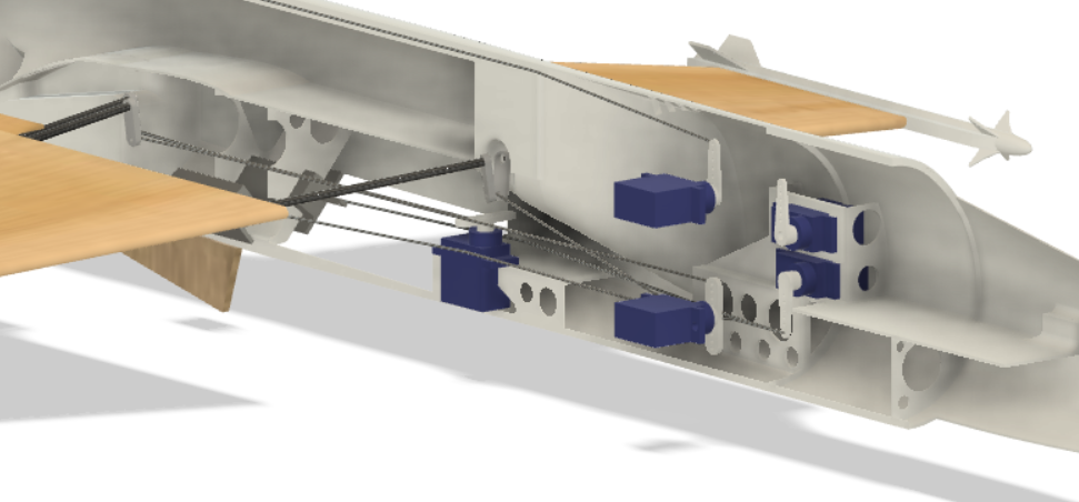
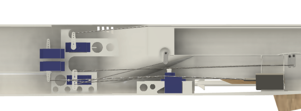
Servos 1.PNG

Servos 2.PNG


All four servos are visible in these pictures with linkages for most of them. I did not add linkages for the rudder because I was lazy but the control rod just runs parallel to the elevator control rod to the tail and will run to a PLA bell crank (not yet in CAD but will mount in the larger hole in front of the aileron servo) for the nose gear if that option is selected. The link from the gear servo to the nose gear is also not in CAD because the PLA nose gear mount is not yet present, but it should be pretty clear how it is installed.
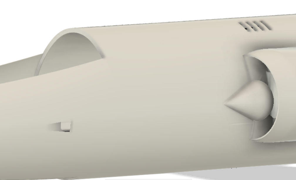
Battery Vents.PNG

Finally, the battery vents consist of a conformal inlet in the nose and vents above the main inlets for exhaust.
 

telnar1236

Elite member
Here is the first set of STL files. Now that it is possible to start printing the F-104 it's time to give a couple of notes on assembly. The aircraft is assembled as a left half and a right half almost completely before being glued together down the middle. This should make access to everything very easy until the final steps. There is some minor complexity with pushrod joiners that I'll explain later, but it's mostly just to make things as easy as possible and isn't strictly necessary.

These STL files are for the right fuselage half and are intended to be printed with 0% to 3% infill (depending on how good your 3D printer is at bridging gaps) in LW PLA. I tend to extrude at 57% of the rate needed with normal PLA which gives me a good balance between weight and strength. Wall layer thickness is two and the top and bottom should also be two layers thick. Some parts will need a brim, and most will need carefully placed supports. Additionally, I have included an STL file for the full right half fuselage and left half fuselage if anyone wants to slice it differently. I'll also release the GCode soon so that anyone with a similar printer can simply load it.

I plan to print the right fuselage and do a test fit before printing the left fuselage in case any changes need to be made, and I'd recommend doing the same, but feel free to go ahead of where I am and experiment too.

Edit: added a picture to show expected orientation when printing
FuseR1andR2_3dprint_setup.PNG
 

Attachments

  • FuseR1.stl
    184.7 KB · Views: 0
  • FuseR2.stl
    316.6 KB · Views: 0
  • FuseR3.stl
    694.5 KB · Views: 0
  • FuseR4.stl
    284.4 KB · Views: 0
  • FuseR5.stl
    495.4 KB · Views: 0
  • FuseR6.stl
    435.2 KB · Views: 0
  • FuseL.stl
    2.2 MB · Views: 0
  • FuseR.stl
    2.1 MB · Views: 0
Last edited:

telnar1236

Elite member
Here are the G-Code files. They should work on an Ender 3 or similar (I have a modified Voxelab Aquila which is what they were generated for). The parameters are for e-sun LW PLA but should work with most LW PLA with foaming. The extrusion rate needs to be turned down manually on the printer. There are 3 prints, and all are currently untested, but I have the first one on the printer now and will update this post if any of them have problems.
 

Attachments

  • Right Fuselage Half.zip
    14 MB · Views: 0

tomlogan1

Elite member
Here are the G-Code files. They should work on an Ender 3 or similar (I have a modified Voxelab Aquila which is what they were generated for). The parameters are for e-sun LW PLA but should work with most LW PLA with foaming. The extrusion rate needs to be turned down manually on the printer. There are 3 prints, and all are currently untested, but I have the first one on the printer now and will update this post if any of them have problems.
Also using Voxlab Aquila with updated firmware. G-Codes still OK? Using Prusa slicer but I do have access to Cura if needed.
 

telnar1236

Elite member
Also using Voxlab Aquila with updated firmware. G-Codes still OK? Using Prusa slicer but I do have access to Cura if needed.
I think it should work with the updated firmware. I don't think the flavor of G-Code has changed. I pulled the first two parts off the printer this morning (pictures this evening) and there were some minor issues with removing the supports, so you might be able to get better G-Code slicing yourself, but what I posted also works fine.

In terms of slicer, any should be fine with the STL files. I used the Voxelab slicer to generate the G-Code I posted since it tends to have fewer issues directly translating the STL into a part, but I also checked slicing in Cura and it looked fine. I haven't tested Prusa with them, but the minimum wall thickness is 0.8, so it should most likely work.

Also, a quick note: these parts are solids and should not be printed using vase mode or thin wall printing.
 

telnar1236

Elite member
First two fuselage sections printed, cleaned up, and glued together. There were a few minor issues removing the support material because the material of the fuselage itself is only one layer thicker and LW PLA foams making it harder to remove. I'd recommend having the STL file in front of you as you remove the material to make sure you are only removing what you need to, and some CA glue to fix any cracks you might accidentally make.
20220824_181517.jpg

20220824_181531.jpg
 

telnar1236

Elite member
A couple quick notes on assembling the second two sections (R3 and R4). First, you need to be very careful removing the support material. I broke less of it than with the first two sections, but only because I knew what to expect. The wing slot is filled in my G-code, but easily cleared with a knife.

Second, only if building with leading edge flaps, it is critical to align the holes for the torque tube in R3 and R4. I did this by running a bbq skewer through both and then sliding them together along it. If the holes don't line up on both sides, then the LE flaps cannot be used.
 

telnar1236

Elite member
The right half of the fuselage is now printed, and everything goes together pretty much as intended so here are the STL files and G-Code for the left half as well as some pictures. Care needs to be taken removing the support material if using the G-Code I provided, or you can slice the STL files yourself pretty easily. The only real areas to watch out for are making sure that the LE flap holes are aligned as previously described, and the tight fit of the ESC holder and wire channel. My ESC fits, if barely, but if you have larger one, you might need to trim a bit, and you definitely will need to carve out the wire channel a bit unless your fan has tiny connectors (I forgot to increase the size when I decided to go with a 40A ESC instead of a 30A one).

Pictures:
20220826_183900.jpg

20220826_183913.jpg


And STL files/G-Code:
 

Attachments

  • FuseL1.stl
    184 KB · Views: 0
  • FuseL2.stl
    331.9 KB · Views: 0
  • FuseL3.stl
    687.7 KB · Views: 0
  • FuseL4.stl
    284.7 KB · Views: 0
  • FuseL5.stl
    549.9 KB · Views: 0
  • FuseL6.stl
    472.9 KB · Views: 0
  • Left Fuselage Half.zip
    13.7 MB · Views: 0

telnar1236

Elite member
I was finally able to get around to printing the left fuselage half as well (my 3D printer had an issue that took a few days to resolve, and I left my right fuselage section on a windowsill for a few seconds where my dog promptly jumped on it to bark on a cat, so it needed to be reprinted). Everything works and I didn't encounter anything I have not noted already. When I was printing the sections L3 and L4, the wires to the extruder snagged on the print and caused it to fail, but when I ran the same G-code again I did not have any problems. It's worth looking out for but does not seem to be a major issue. The next steps are to start installing the EDF unit and servos and to laser cut the wings.

20220906_152757.jpg

20220906_152742.jpg
 

telnar1236

Elite member
All the electronics are now installed in their respective halves. I didn't need to make any changes beyond those I already noted.
20220915_173113.jpg

Unfortunately progress has been pretty slow. The perfect storm of events that started with the problems I listed in the previous post has continued with my PC hard drive bricking itself, so I can't do any design work until a replacement arrives. Fortunately the STL files are almost completely uploaded here or are present on an SD card, so I'm not trying to start the CAD again from scratch. However, at this point, the U-2 variant will probably be a clean sheet design when I get to it.
 

telnar1236

Elite member
Finally got my computer back up and running, so here are the drawings for the wings. They are intended to be laser cut using the laser GRBL software but can also be done by hand (I'd recommend not doing flaps if cutting by hand). They are 232 mm wide (scale is 0.45mm per pixel). The wings are meant to be built by cutting the core out of 1/16" plywood then laminating 1/16" balsa on the top and bottom with the grain going out along the wing. The channels for the TE flap torque tubes are meant to be removed after the first side of balsa is put in place to allow a disconnected piece of plywood to be properly situated. If laser cutting, depending on the size of the laser cutter, the wings may need to be split into multiple parts to cut, so if that is necessary, they should first be split front to back and then any splits should be as close to the wingtip as possible. There are three versions of the drawing: one with both LE and TE flaps, one with TE flaps, and one with just ailerons.
Wing Drawing 5_6ch TE_LE Flaps.png Wing Drawing 5_6ch TE_Flaps.png Wing Drawing 4ch.png
And here are the settings I use with Laser GRBL to go from the PNG file to the tool path. It looks crooked, but the cut does not end up crooked.
Laser GRBL Parameters.png
 

telnar1236

Elite member
I laser cut the first wing core today and attached the balsa skin on one side. I accidentally put it on at 90 degrees to where it should be, so I'm going to position that section of skin on the top of the wing where it will have less of an impact (the wing should still be easily strong enough). I had to divide the wing in half which I did front and back exactly at the halfway point of the picture, but otherwise didn't have any trouble with the cut. And I realized that I had left some support material in the slots for the wings, but once that was removed, I was able to do a dry fit and everything seemed to fit together as intended.
20220930_205007.jpg
20220929_205702.jpg
 

telnar1236

Elite member
The wings are now finished and installed on their respective fuselage halves. The torque tubes work great with very little play and everything fits together nicely. Assembly was a bit fiddly and not at all difficult. Before covering the wings, I'll sand down the leading and trailing edges to make the wing a bit more airfoil shaped.

The two pictures show the control surfaces flush with the wing and then deflected.

20221008_213936.jpg

20221008_213956.jpg
 

telnar1236

Elite member
Here is the drawing for the tail. The picture is 268 x 121 mm (scale is 0.22 mm/px). If it is being laser cut, the settings should be the same. I didn't include any holes to lighten the structure to reduce the risk of flutter.
Tail Drawing All.png
 
The wings are now finished and installed on their respective fuselage halves. The torque tubes work great with very little play and everything fits together nicely. Assembly was a bit fiddly and not at all difficult. Before covering the wings, I'll sand down the leading and trailing edges to make the wing a bit more airfoil shaped.

The two pictures show the control surfaces flush with the wing and then deflected.

View attachment 230984
View attachment 230985
That looks great.
 

telnar1236

Elite member
I was finally able to get around to finishing the main gear. The original idea was to use the natural elasticity of ABS, but that ended up resulting in gear that was either too stiff, too weak, or far too large. I printed quite a few test pieces and none of them worked as I wanted them to, so I went with spring loaded gear instead. While more complex, they are a known quantity, so they should work. I am a bit concerned about clearances, but everything seems to work in Fusion360.

Main Gear V3.png


Main Gear Stowed.png
 
Last edited:

telnar1236

Elite member
Printed the first landing gear. Everything works right. I calculated that the gear would be straight when one side of the main gear is loaded at 240 grams which should match the weight distribution for a 600 gram plane (80% main gear, 20% nose gear) and it worked out almost exactly. The gear bottoms out at 789 grams so it can accept a 2.6 g load which is a pretty bad landing. One gear strut weighs in at 9.5 grams which is better than I hoped, and everything is easy to assemble. The pin for the hinge is a paperclip, and the rest of the gear is printed in ABS. For printability, I designed the lower part of the gear strut as two pieces, and they slot together using a 2mm pin for alignment (a bbq skewer works and is what I used). The axle for the wheel and the pin at the top are also 2mm. To ensure adequate strength, I would recommend acetone smoothing the printed parts before assembly to reduce the likelihood of cracking, or at least painting the outer surfaces with a thin layer of CA. I'm definitely happy with the design and will likely print several to use on short term projects since it's a nice scale and very easy to work with.

20221103_220855.jpg

20221103_213920.jpg
 

Attachments

  • Final Main Gear Bottom.stl
    33.7 KB · Views: 0
  • Final Main Gear Middle.stl
    50.5 KB · Views: 0
  • Final Main Gear Top.stl
    71.4 KB · Views: 0
Last edited:

telnar1236

Elite member
The first retract unit is installed in the airframe. Everything fits and works, but the clearance between the wheel and front of the gear bay is very small and the wheel sticks a bit too far out of the fuselage when retracted, so I want to try and find a smaller wheel. If anyone has suggestions for a cheap lightweight wheel with a diameter smaller than 30mm (current is 35mm) and a 2mm hole, I'd love to hear it. Otherwise, I'm pretty happy. The bare metal strut between the retract unit and the 3D printed strut looks kind of funny, but that's unavoidable because of the geometry of the retract unit.

20221112_231314.jpg 20221112_231326.jpg 20221112_231405.jpg 20221112_231415.jpg