
leaded50
Legendary member
In 1943 the RAAF (Royal Australian Air Force ) gave the go ahead to CAC (Commonwealth Aircraft Corporation) to develop their new fighter – the CA-15.
Despite the final layout the CA-15 would have, leading to comparison to the P-51 Mustang, in fact the initial design was much more closely modelled on the German Focke Wulf 190. Chief Designer of the CA-15, Fred David, was extremely impressed by the assessments being made of the then new German fighter and it was this that provided his inspiration. His initial design intended to use a radial engine like the FW 190 – principally the huge Pratt & Whitney R-2800 Double Wasp.
Which really should not be a surprise. Because Fred David – full name Friedrich David – was an Austrian Jewish refugee who had previously worked for Heinkel. He had also helped develop the Mitsubishi A5M Claude fighter and the D3A Val dive-bomber for Japan before the war.
With RAAF´s successful CAC Boomerang as well, it is safe to say that Fred David knew a thing about radial-engine combat aircraft design.
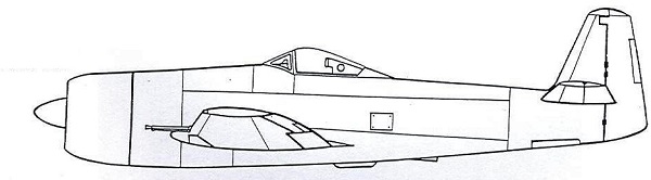
No, this is not the FW190, but first designs on the CA - 15!!
Unfortunately, while the Australians would prove capable of designing and building the airframes of modern aircraft, they had a problem that has bedeviled so many promising designs – engine supply.
The CA-15 was initially hoped to have the Pratt & Whitney R-2800-21 Double Wasp – the same as used in the P-47 Thunderbolt. But in mid-1943, CAC was informed this engine wouldn’t be available and so redesigned the Kangeroo to use the R-2800-10W, as used by the F6 Hellcat. Unfortunately, this engine utilized superchargers instead of a turbocharger and meant that the CA-15 would no longer be a high-altitude fighter, instead specializing in mid-to-low level combat.
The aircraft’s projected performance with the -10W was estimated to be a maximum speed of 365 mph at sea level, 436 mph at 25,000 ft and that it would have an initial climb rate of 4,200 fpm.
On top of this, development was further slowed when CAC was granted a licence to produce the North American Mustang. After all, the Mustang was on route to becoming one of the Allies key fighter aircraft and getting them into service with the RAAF in numbers was more important than an aircraft that was still some way from service.
Fred David persisted, but again engine issues cropped up. In May 1944, with the prototype already being constructed, the team was told that the Double Wasp -10W was no longer available. Instead, they would have to use the R-2800-57, which again used a turbocharger, necessitating even another fuselage redesign to fit it. This once again slowed down the project.
In August, the prototype was about 50% complete when, in a theme you will no doubt now be expecting, CAC got told the Double Wasp -57 would not be available to them. In fact, no Pratt and Whitney engine would be. So, the team set about looking for another engine for their aircraft.
They found it the Roll Royce Griffon 125 that was then under development.
The use of the water-cooled Griffon entailed a major redesign of the prototype, but David and the CAC team did a remarkable job. It was at this point that the superficial similarity to the P-51D came about. With its tear drop canopy, under belly air scoop, square-clipped wingtips and initially intended armament of six 0.5-calibre Browning heavy machine guns, the CA-15 certainly looks like a beefed-up Mustang. But in fact, as this long-winded discussion on the aircraft’s origins I hope makes clear, that similarity is very much coincidental .
By early 1945 the CA-15 prototype was ready, simply waiting for the new Griffon engine to be delivered.
Guess what happend next?
Rolls Royce said the Griffon 125 wasn’t going to be available until late-1945. In fact, they eventually cancelled it, but this was in the future and ultimately not a concern for the Aussie team. They wanted an engine, and they wanted it now!!!!
So, they got two Griffon 61s on loan for fitting in the CA-15. This engine, was the same as fitted to the Spitfire MK.XIV.
With this, finally, the CA-15 got a engine. The aircraft needed a surprisingly few number of tweaks to improve performance, and once handed over to the RAAF test pilots in July the CA-15 was reported to be an excellent aircraft, with great handling and superb visibility for the pilot. With the Griffon 61, the CA-15 had a good speed amd climb rate too. Mustang had a top speed of 444 mph .. the "Kangaroo" did 502 mph in a test.
The aircraft with the nickname of ‘Kangaroo’ was ready for testflights!.
But, as with so many of the late-war ‘super prop’ aircraft, the CA-15s fate had long been sealed. The reason for the long delay in repairing the aircraft after its prang was that it was already obsolete.
In 1946 the RAAF had received its first jet fighter, the de Havilland Vampire. And while David’s team were still tinkering with the CA-15, the new jets very much showed how the future was going to be.
In 1950, Rolls Royce requested the return of their loaned Griffon engines. With no need for the aircraft with the RAAF, and the project essentially being now little more than a vanity project for CAC, the CA-15 project was scrapped.
Which was, quite frankly, stupid as the aircraft should have been preserved, but seems to have been all too common with aircraft of this type.
The pity really is that the aircraft did not get its initial engine layout. Had this occurred, the CA-15 may well have become the primary fighter bomber of the RAAF throughout the Pacific in 1944-45. And instead of the “might-have-been Aussie Mustang”, we would be talking about the “Aussie Thunderbolt”.
Or even “the Aussie Focke-Wulf”?
Anyway its a lovely unique warbird only made as one prototype, and been on my buildlist for some time. Now i had time for it. Builds in 1:10 scale , thats
Wingspan: 1097 mm
Length: 1104 mm


Despite the final layout the CA-15 would have, leading to comparison to the P-51 Mustang, in fact the initial design was much more closely modelled on the German Focke Wulf 190. Chief Designer of the CA-15, Fred David, was extremely impressed by the assessments being made of the then new German fighter and it was this that provided his inspiration. His initial design intended to use a radial engine like the FW 190 – principally the huge Pratt & Whitney R-2800 Double Wasp.
Which really should not be a surprise. Because Fred David – full name Friedrich David – was an Austrian Jewish refugee who had previously worked for Heinkel. He had also helped develop the Mitsubishi A5M Claude fighter and the D3A Val dive-bomber for Japan before the war.
With RAAF´s successful CAC Boomerang as well, it is safe to say that Fred David knew a thing about radial-engine combat aircraft design.
No, this is not the FW190, but first designs on the CA - 15!!
Unfortunately, while the Australians would prove capable of designing and building the airframes of modern aircraft, they had a problem that has bedeviled so many promising designs – engine supply.
The CA-15 was initially hoped to have the Pratt & Whitney R-2800-21 Double Wasp – the same as used in the P-47 Thunderbolt. But in mid-1943, CAC was informed this engine wouldn’t be available and so redesigned the Kangeroo to use the R-2800-10W, as used by the F6 Hellcat. Unfortunately, this engine utilized superchargers instead of a turbocharger and meant that the CA-15 would no longer be a high-altitude fighter, instead specializing in mid-to-low level combat.
The aircraft’s projected performance with the -10W was estimated to be a maximum speed of 365 mph at sea level, 436 mph at 25,000 ft and that it would have an initial climb rate of 4,200 fpm.
On top of this, development was further slowed when CAC was granted a licence to produce the North American Mustang. After all, the Mustang was on route to becoming one of the Allies key fighter aircraft and getting them into service with the RAAF in numbers was more important than an aircraft that was still some way from service.
Fred David persisted, but again engine issues cropped up. In May 1944, with the prototype already being constructed, the team was told that the Double Wasp -10W was no longer available. Instead, they would have to use the R-2800-57, which again used a turbocharger, necessitating even another fuselage redesign to fit it. This once again slowed down the project.
In August, the prototype was about 50% complete when, in a theme you will no doubt now be expecting, CAC got told the Double Wasp -57 would not be available to them. In fact, no Pratt and Whitney engine would be. So, the team set about looking for another engine for their aircraft.
They found it the Roll Royce Griffon 125 that was then under development.
The use of the water-cooled Griffon entailed a major redesign of the prototype, but David and the CAC team did a remarkable job. It was at this point that the superficial similarity to the P-51D came about. With its tear drop canopy, under belly air scoop, square-clipped wingtips and initially intended armament of six 0.5-calibre Browning heavy machine guns, the CA-15 certainly looks like a beefed-up Mustang. But in fact, as this long-winded discussion on the aircraft’s origins I hope makes clear, that similarity is very much coincidental .
By early 1945 the CA-15 prototype was ready, simply waiting for the new Griffon engine to be delivered.
Guess what happend next?
Rolls Royce said the Griffon 125 wasn’t going to be available until late-1945. In fact, they eventually cancelled it, but this was in the future and ultimately not a concern for the Aussie team. They wanted an engine, and they wanted it now!!!!
So, they got two Griffon 61s on loan for fitting in the CA-15. This engine, was the same as fitted to the Spitfire MK.XIV.
With this, finally, the CA-15 got a engine. The aircraft needed a surprisingly few number of tweaks to improve performance, and once handed over to the RAAF test pilots in July the CA-15 was reported to be an excellent aircraft, with great handling and superb visibility for the pilot. With the Griffon 61, the CA-15 had a good speed amd climb rate too. Mustang had a top speed of 444 mph .. the "Kangaroo" did 502 mph in a test.
The aircraft with the nickname of ‘Kangaroo’ was ready for testflights!.
But, as with so many of the late-war ‘super prop’ aircraft, the CA-15s fate had long been sealed. The reason for the long delay in repairing the aircraft after its prang was that it was already obsolete.
In 1946 the RAAF had received its first jet fighter, the de Havilland Vampire. And while David’s team were still tinkering with the CA-15, the new jets very much showed how the future was going to be.
In 1950, Rolls Royce requested the return of their loaned Griffon engines. With no need for the aircraft with the RAAF, and the project essentially being now little more than a vanity project for CAC, the CA-15 project was scrapped.
Which was, quite frankly, stupid as the aircraft should have been preserved, but seems to have been all too common with aircraft of this type.
The pity really is that the aircraft did not get its initial engine layout. Had this occurred, the CA-15 may well have become the primary fighter bomber of the RAAF throughout the Pacific in 1944-45. And instead of the “might-have-been Aussie Mustang”, we would be talking about the “Aussie Thunderbolt”.
Or even “the Aussie Focke-Wulf”?
Anyway its a lovely unique warbird only made as one prototype, and been on my buildlist for some time. Now i had time for it. Builds in 1:10 scale , thats
Wingspan: 1097 mm
Length: 1104 mm
Last edited:


") . And some minor stuff on the 3D view drawing with measurements, will give much inort on how, and what
. And some minor stuff on the 3D view drawing with measurements, will give much inort on how, and what 


