CranialRectosis' Twitchity Mini-Hex build

cranialrectosis

Faster than a speeding face plant!
Mentor
Twitchity caught the multi-rotor bug and got it bad. So bad in fact that he got a CNC machine so he could build custom frames from advanced materials.

His first prototype frame is a doozy. :)

The Twitchity mini-hexacopter frame is made from G-10. My kit weighed in at 130 grams with all the screws nuts and standoffs. Fully built with motors and ESCs the all up weight is 411 grams. From motor shaft to motor shaft the copter is 330mm wide and 279mm long. As such the copter will accomodate 6" rotors. :D

The Parts

Frame:
This frame is unique today. It was built by our very own Twitchity. If you want one, you need to ask him. :)

Motors and rotors:
I went with the SunnySky X2204 2300kv from BuddyRC.
Rotors are the HQ 6045 rotors from GotHeliRC.com

Flight controller and ESCs:
I am running the Naze 32 Rev5 from RotorGeeks.com
The ESCs are eMAX 12a Simon Series (BlHeli) ESCs from MultirotorMinis.

Receiver:
I chose the FrSky D4R-II from Aloft Hobbies.

Thoughts:
I have flown a few batteries now and this is a VERY powerful copter. It begs to be weighted down with FPV gear. I need to add a Mobius tomorrow and see how it looks from the copter.

Current build includes a small 'canopy' from an Easter egg and KISS 18a ESCs. I love how they fly but I find them difficult to work with. The light colored G10 frame makes it simple to repaint this copter any color you like. It took me 15 minutes of sanding to get the old paint and some pretty good dings worked out and the copter was ready for painting.

Final Build Weight is 411 grams (without battery).
Current Build Weight with canopy and with new KISS Escs is 394 grams (without battery).
Current Photo:
 

Attachments

  • P2170002.JPG
    P2170002.JPG
    1.7 MB · Views: 27
Last edited:

cranialrectosis

Faster than a speeding face plant!
Mentor
Flight Controller And Receiver

I am completely envious of the Spektrum sat and how you can solder it directly to most multiwii type boards. A few months ago I made the swap from FlySky (Turnigy 9X) to FrSky so I could take advantage of the smaller 4 channel D4R-II four channel receiver. Because I am using PPM, I can deliver (safely) 6 channels on one wire. The D4R-II is small and light but I decided to unwrap it and make it smaller anyway. I removed all the pins and the cardboard cover.
PB010012.JPG

I had some two row 90 degree headers, removed the bottom row and soldered the headers pointing back over the receiver. I also soldered a vertical header to channels 3 and 4 signal. Channels 3 and 4 get jumped with the included jumper to put the receiver in PPM mode. With the new pins attached to the receiver, I removed the entire receiver header row from the Naze. I put a bit of two sided foam tape on the top of the receiver, lined up the power, ground and signal pins on the receiver to the solder pads for same on the Naze and soldered my FrSky receiver directly to the Naze 32.
PB010016.JPG PB010019.JPG

Care must be taken here and I am not completely sold on the idea. The receiver has a tiny button on top that I have isolated from the bottom of the motor pins on the Naze with the two sided foam tape. If the button depresses, I think I am in deep doo-doo...

It isn't as pretty as the Spektrum solution but it is tiny and light and I now have one unit of FCB/Receiver to install.
PB010017.JPG

I used four 15mm standoffs to lift the FCB/Receiver up from the center plate of the frame and with 8mm (can't find these in nylon yet) steel screws I mounted the board between a sandwich of 3mm O rings. For each standoff, one O ring is below the board to isolate it from vibration and one is above the board to isolate it from the steel screw. I used eight O rings and gently and evenly compress them with the screws.
PB060026.JPG

I also mounted the five 30mm standoffs (am getting 35mm to allow for the frame's camera mount) as per Twitchity's instructions. Once you put the two lower plates together, you can no longer mount these standoffs so do it now. I used nylon nuts and cut the threads of the standoffs clean at the nut as there is only 3mm between the bottom and middle plates.
 
Last edited:

cranialrectosis

Faster than a speeding face plant!
Mentor
Power and ESCs

I made my power harness from 16awg and 20awg hobby wire. I am powering six motors plus I want one 12V rail for battery voltage monitoring by the Naze 32 and a spare 12V rail for lights. Instead of making a 1 into 8 joint, I merged two motor rails and the spare light rail with the battery lead and made a 4 into 4. This makes for a flatter knot of wires and uses less wire. It also makes the final solder joint simpler to manage. I used Soma's WarpQuad power loom method of holding the wires together with tight heat shrink on either side of the central joint during the soldering job.

This method is not a proper pigtail as it lacks the copper wire binding the two halves of the joint. However, if there is ever enough stress on this joint for it to pull apart, I figure I want it to. :)

Once the basic power loom was assembled, I moved on to cleaning up the ESCs. I am pretty nerdy and remove all the manufacturer's wire and solder from an ESC so I have no mixes of solder. Manufacturers tend to use solder with more tin that melts at a higher temperature. It may not blend well with mine and so the chance of a cold solder joint is higher. After stripping the ESCs, I tin them with my own solder and polish them with rubbing alcohol.
PB060022.JPG

At least this time I put the right battery connector on the harness. :black_eyed:

Because I solder my motors directly to the ESCs and the ESCs directly to the power harness, measuring the wires here is critical. One short wire and you have an ugly splice, one long wire makes an ugly loop you may not have room for. I loosely assembled the frame to measure out the wiring so I could solder the ESCs to the power harness. I have the spare rails taped off to keep those leads separate as they are different lengths than the motor leads. I used sandwich bag ties (another Soma WarpQuad lesson) to hold the wires in place as I trimmed wires and soldered ESCs.
PB060023.JPG PB060024.JPG PB060027.JPG

With the power wires all correct lengths and the ESCs soldered on, I could attach servo wires for ESC signal, power and ground. I use Arduino wires to make these and keep the servo wires that come with the ESCs for other purposes. The Arduino wires allow me to use wires that match the colors of my build. In this case I used red and brown for power and ground from ESC 1 and for all signal wires I used purple and green. :)
PB070030.JPG PB070031.JPG

At this point, I can CAREFULLY mount the center plate and route all the wires. There is 3mm between the top and center plates; less where there is a standoff to the top plate. It takes time to put these together without pinching wires, sandwich ties or no. I also at this time soldered a JST to the 12v rail for voltage detection and soldered another JST to a 5v piezo and fisched it between plates.
PB070032.JPG
 
Last edited:

cranialrectosis

Faster than a speeding face plant!
Mentor
Motors and final assembly

Now I get to mount the SunnySky motors. I have trimmed motor leads and not trimmed motor leads. Trimmed motor leads are a hassle to maintain particularly with ESCs with the motor wire pads between the FETs. I chose not to trim leads today.

It was at this point that I realized that while Twitchity had managed to get the screw mounting holes right, the center hole for the shaft was too small. The motor shaft is clipped on the bottom of the motor with a small C clip (I have other nastier names which I will not use here, maybe on RC Groups later though...) and that clip as well as the nylon washer at the bottom needs to be able to spin. The hole was too tight.

Luckily this is G-10 not CF so I pulled out a 1/4" drill and reamed the holes out until a properly centered SunnySky can spin freely (thanks for the pointers, Mustang). Twitchity was making changes to the design as I built. I'm pretty sure no future Twitchity design will need to be reamed out. :)

I also used small split-ring type washers between my motor mount screws and the G-10 booms. This should keep me from running the screws up into the motors too far (easy to do on pan type motors) and to hopefully prevent them from backing out. I am not a fan of loctite. I tend to make a mess. :black_eyed:

Even 1" heat shrink will not slide over both a SunnySky 2204 and the boom so I put the heat shrink on first and then solder on the motors being careful to align the leads so all my motors will spin the right directions the first time.
PB070035.JPG

I then fisched all the servo wires through the center of the frame to the square cut out Twitchity thoughtfully left below the FCB and out the right side. I am still partial to the KK2 and having my motor leads on the right so I adjust the Naze 32 by 90 degrees of yaw to offset and allow the change in orientation.

With the motors all mounted, the wires all ran and connected I mounted the ESCs with two sided tape to the booms. This protects them from some shock and vibe, keeps them level under the heatshrink and isolates the pins from the booms if you use CF which is conductive.
PB070036.JPG

Now I get to test motor direction. I grab for my safety goggles, cross my fingers and keep one eye on the fire extinguisher. :)

When I am building out the signal wires for the ESCs I put little bits of blue painter's tape on my cutting board. I label these with the motor number and the direction so I don't forget and screw up the deal. This is particularly important to get right. The more you solder to the ESCs the more chance you have of cooking a FET. I actually knocked a FET completely off with a hot soldering iron and had to re-solder it to the ESC. I can only pray it works. Use whatever cheats you need to get these right. You don't want to have to resolder once you shrink the heatshrink.

Once you get the motors right, hit the heatshrink with the heatgun and start programming the Naze 32.
PB070037.JPG

This is my fourth Naze and I have a routine for setting one up. It takes me about 10 minutes to rotate the board, synch ESCs (thank you Mustang for that lesson again), enable motor stop, enable PPM and voltage detection and set a basic PID. Baseflight allows me to test motor start up and direction one at a time and also allows me to monitor the accelerometers with the motors running so I can get a feel for how much vibration is hitting the FCB.

Once the Naze is set up it is time for rotors, testing CG and mounting a battery. I like to find CG by balancing the copter on the back of my workshop chair. CG should be directly under the FCB if the design is good. Looks to me like Twitchity nailed it. :applause::applause::applause:
PB070040.JPG

CG is good, I have lipos ready to go, rotors attached and so I gave it one last screw tightening before the maiden. Of course after maiden I will return to every single screw on the copter and check it for loosening and check all electronics for excess heat. My maidens are short and flown in acro mode.

Thank goodness for summer. I hate doing a maiden over hard clay and sand. Now I have grass!

Ladies and gentlemen of FliteTest, it is my singular privilege to present to you the Twitchity Mini-Hex.

PB070043.JPG PB070044.JPG PB070045.JPG PB070048.JPG PB070050.JPG PB070051.JPG

I would like to thank Twitchity for sending me this frame and allowing me to present the build here on our forum.

This was a challenging build and a ton of fun. It was a pleasure to meet Twitchity via Skype and build with him. If you have not tried it yet, Skype building can be a blast.

Lastly thank you all for reading and Mr Kapper for this marvellous community.
 
Last edited:

Twitchity

Senior Member
Fantastic writeup cranialrectosis. It was a pleasure joining you over Skype for the build, and I learned a lot of useful information for my future builds and projects.

The hex came out even better than I could imagine; your attention to detail still amazes me. That green really pops out in the pictures compared to how it looked over Skype. Can't wait to see it in action once you get the settings all dialed in :)
 

Twitchity

Senior Member
Outstanding work

Is there any anti vibration mount for the camera in this kit ?

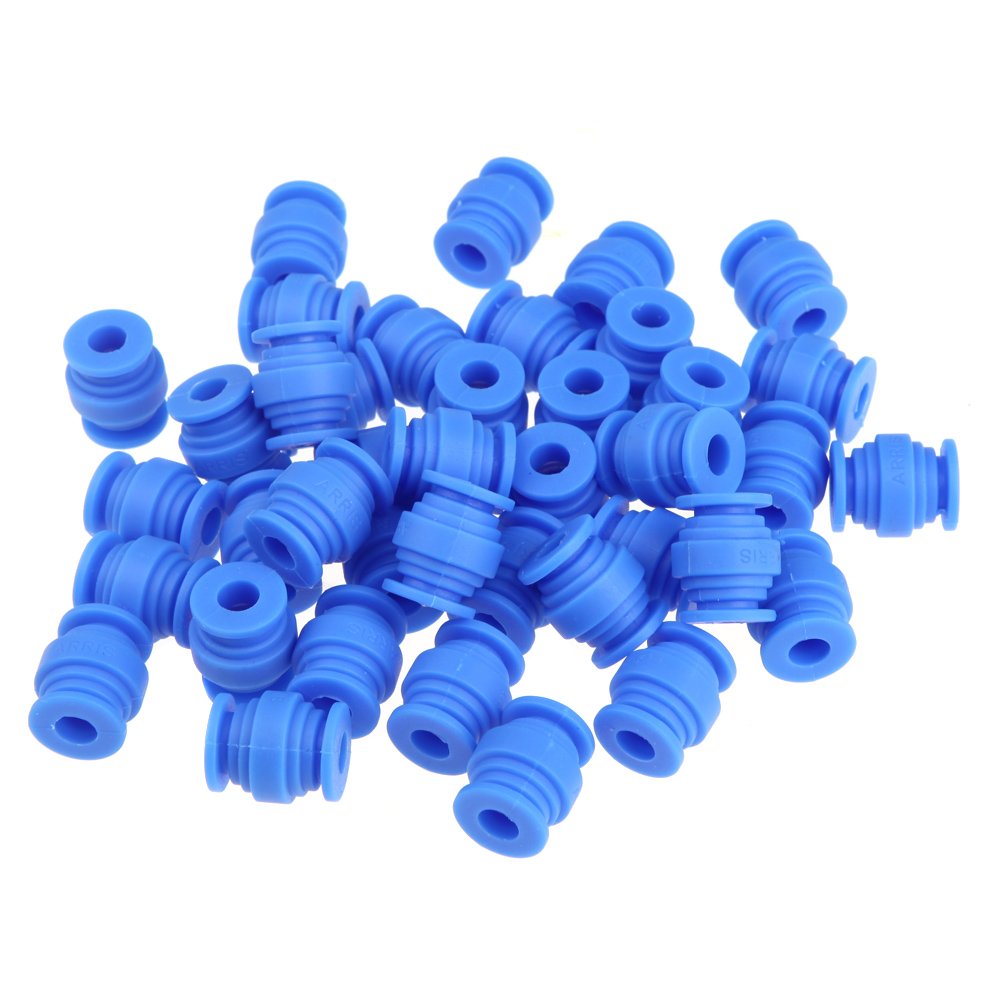
No anti vibration mount for the camera on this design (yet). I just received some gimbals anti-vibration dampening balls that will be incorporated in V1.5 or V2.0 (depends on my mood that day ;) ) that will provide vibration dampening to the FC and cameras. These will be used on the quad build I'll be doing this week, and will make their way into future designs.

617v84jlq7L._SL1500_.jpg


Since I'm just getting my feet wet in the frame making process, I will take any and all recommendations on what to include/exclude on my designs to better suit the needs/wants of the community. I hope to have a few frames with the vibration dampening system made out of black G10 the weekend of July 12th that I will be selling. Hopefully I'll have more feedback on the design by then so I can make any improvements necessary for the next version of the hex.
 

e_lm_70

Senior Member
No anti vibration mount for the camera on this design (yet). I just received some gimbals anti-vibration dampening balls that will be incorporated in V1.5 or V2.0 (depends on my mood that day ;) ) that will provide vibration dampening to the FC and cameras. These will be used on the quad build I'll be doing this week, and will make their way into future designs.

617v84jlq7L._SL1500_.jpg


Since I'm just getting my feet wet in the frame making process, I will take any and all recommendations on what to include/exclude on my designs to better suit the needs/wants of the community. I hope to have a few frames with the vibration dampening system made out of black G10 the weekend of July 12th that I will be selling. Hopefully I'll have more feedback on the design by then so I can make any improvements necessary for the next version of the hex.

In my experience the anti vibration balls works best when you have on the same isolated plate both camera and other component ideally the battery ... more is the mass in the isolated plate, and more free from vibration will be.

This does implies some design decision in a early phase ... just add balls for the camera only does not work that well, it is just a last minute patch, like for example in the black out quad design.
 

cranialrectosis

Faster than a speeding face plant!
Mentor
When I return from Arizona, I will mount a Mobius to ensure the props are out of view and see how much jello exists. I apologize for being absent. I will return next week.
 

FinalGlideAus

terrorizing squirrels
A simple solution is to mount the camera to some strips of foam tape about 10mm thick then hold down with a Velcro strap. Simple yet effective and no annoying vibration balls to work with. Check out my blackout mini h build log for pictures.

A simple and effective way to mount the FC is to mount on nylon standoffs and have rubber O rings above and below it on the thread just like on the Warpquad.
 

e_lm_70

Senior Member
What is annoying on vibration balls ?

Everybody use them for kill vibrations ... all the other system are really dependent of type of foam, the way to fit the cam, the weight of the cam, etc etc.

Put on an vibration isolated plate both battery + camera + FC ... it is a simple receipt that works all the time.
 

FinalGlideAus

terrorizing squirrels
It means having a seperate plate for extra complication and weight, loosing the balls in crash, having to reinstall the balls. I don't see the point when foam works just fine, especially when I need to mount the foam anyway to get the camera pointing up. Vibration plates look fancy but simplicity works wonders.
 

e_lm_70

Senior Member
Losing balls in crash is a good thing, since it help to distribute and absorb the crash

Foam mounting works only up some limits ... it is very camera size dependent and it is very dependent of the level of vibrations in the copter ... it is very not repeatable, since everybody has different type of foam available and will use different way to tight the camera around the foam.

Isolation plates does excellent job with a working result in the 100% of cases. It also avoid to have to think about the control board mounting.

Some small copter have already this design approach, the new big copter are already moving in this direction.

PS: For adjust the camera angle, I use packing expanded plastic (sort of EPO/EPP, but used in the packing for protect many good like TV, etc) and I cut the shape and angle that I need, using a hobby knife. I was using foam before, but it is way more precise and easy to quickly cut the "cone" needed for the job.

PPS: I think about this subject we gave already enough material to think about to "Twitchity" ... so ... looking forward for his progress
 

Invid

Member
Eagerly awaiting video with a Mobius or GoPro to see if (or how much of) the props are visible on the completed hex. I have 6 SunnySky 2204 2300kv motors that don't yet have a home, and this could be it if the geometry is right. I want a hex to go with my Blackout Mini H, and the only reason I didn't already order the BO Hex is the 5" prop limitation. I want more flexibility with the option of 6" props.

The colour options on this build are great too. Looks sharp.
 

Twitchity

Senior Member
Eagerly awaiting video with a Mobius or GoPro to see if (or how much of) the props are visible on the completed hex. I have 6 SunnySky 2204 2300kv motors that don't yet have a home, and this could be it if the geometry is right. I want a hex to go with my Blackout Mini H, and the only reason I didn't already order the BO Hex is the 5" prop limitation. I want more flexibility with the option of 6" props.

The colour options on this build are great too. Looks sharp.

I'm glad you like the design :) The one feature cranialrectosis said that the hex had to have was the ability to run 6" rotors, and then gave me free run for the rest of the build. I should be cutting a new frame tomorrow afternoon that will have the anti-vibration system similar to the quad I'm currently working on http://i998.photobucket.com/albums/af110/twitchity/IMG_20140702_194942_zpsa79c2ad0.jpg.

I should have pictures tomorrow evening, but I would like to see the original design with a GoPro or Mobius to see what it looks like too :)
 

cranialrectosis

Faster than a speeding face plant!
Mentor
A simple solution is to mount the camera to some strips of foam tape about 10mm thick then hold down with a Velcro strap. Simple yet effective and no annoying vibration balls to work with. Check out my blackout mini h build log for pictures.

A simple and effective way to mount the FC is to mount on nylon standoffs and have rubber O rings above and below it on the thread just like on the Warpquad.

Thats the plan, and the little O rings is how I mounted this board. I love it. The foam method I was using left no space under the FCB. The standoffs and O rings allow me to mount the receiver below the Naze. I haven't had any vibe issues yet.

I will try the velcro/foam solution on the Mobius when I get back. Again the attempt will be to see how bad vibe is as I am not really hugely intersted in video. Once I get the 35mm standoffs in, I will use the camera mount that came with the frame with a board cam of some type and start playing more with video.

Who knows, maybe once I start playing with it, my interest will be piqued.