Hello fellow FT fans.
I have long been wanting to build a platform that I know inside and out, yet still feel comfortable enough to put my trust in. I hope you see the humor in that!
I am, among other things, an amateur photographer. I also am a Robotics Mentor and an all around electronics geek.
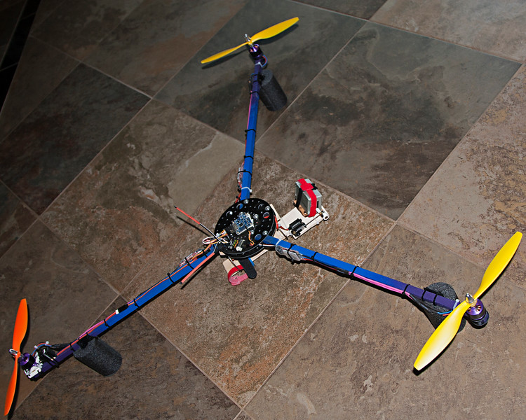
18 months ago I built my first multi-rotor loosely based on the classic David Windestål Tri design. After retrofitting with a 5.8 GHz 200mw VTx, Bluetooth, Battery Monitor, Flip 1.5, RTFQ Red Special motors and RTFQ 20A Fire Red Esc's, 10" Gem Fans, I really started loving what I had. It flew really well. Although, I have not flown it FPV yet, mostly LOS with the occasional glance at the monitor.

About two weeks ago, I was visiting a friend out in the country (Wilton, Ca.) and was flying around his property. It was quite windy and on one pass, I clipped the edge of a tree and it spun out and hit the grass about 8 feet down. A quick look over didn't reveal any damage, so I put it back in the air. WRONG!!!!
About 100 yards out and 150 ft. up, it threw a prop! Yep, no recovering from that! Every prop was busted. Every arm broken. GoPro kept broadcasting, but had ejected it's SD card in the field..... somewhere.
OK, all that to say, I'm using this "opportunity" to build my next project.
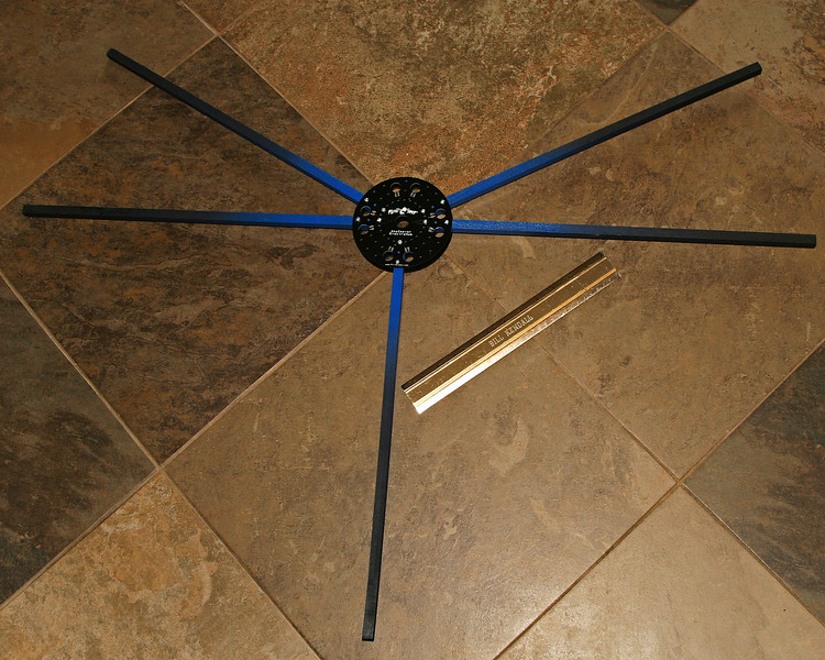
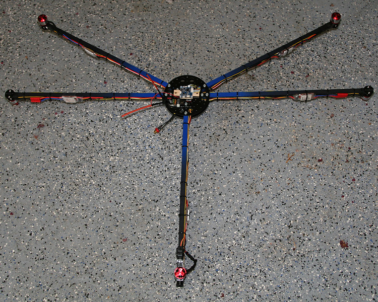
Dragon-Fly Tri
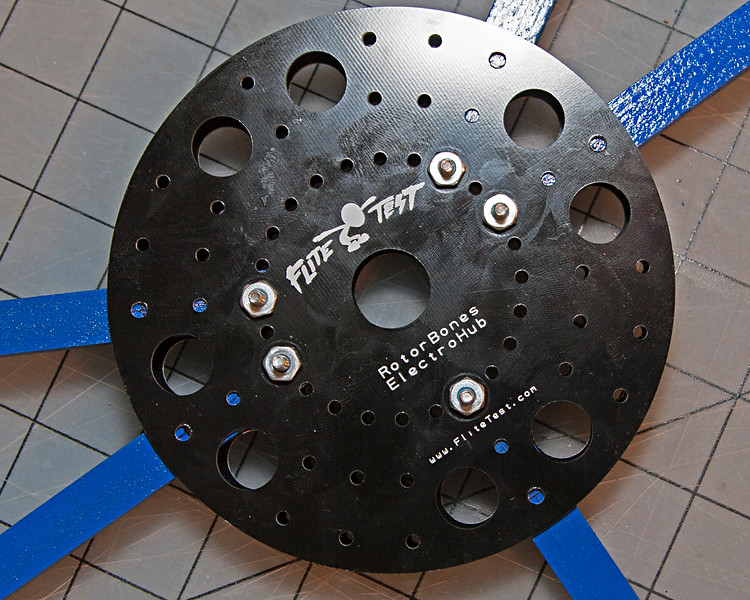
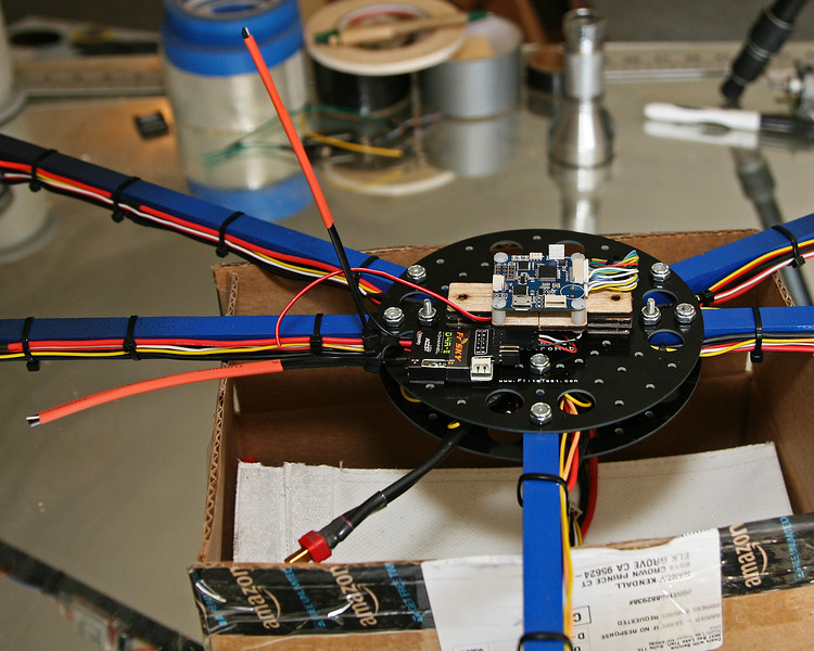
FT ElectroHub
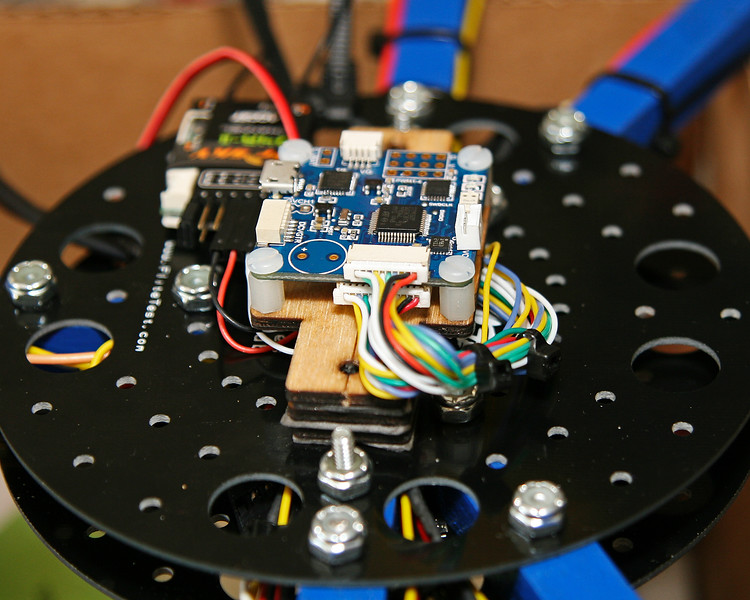
RTFQ Flip32+ Deluxe v5.0
Clean Flight
FrSky D4R-II receiver in CPPM mode.
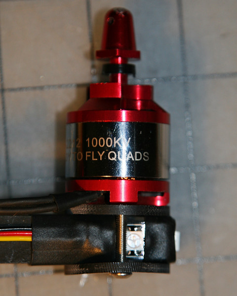
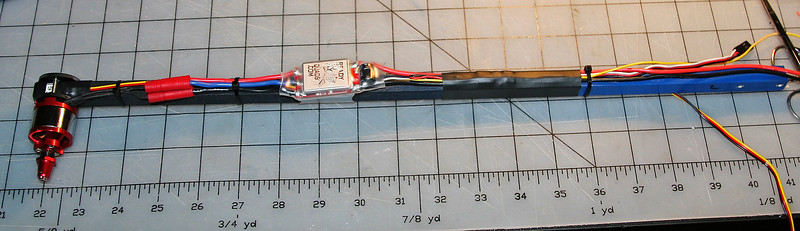
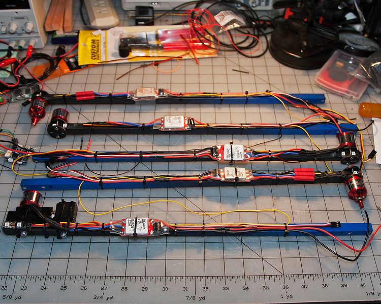
5X RTFQ Red Special 1000Kv 2212 motors (Can't beet the bang for the buck!)
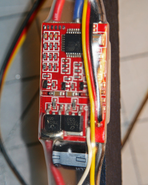
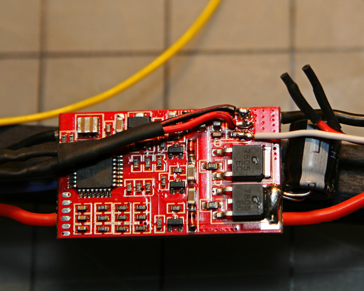
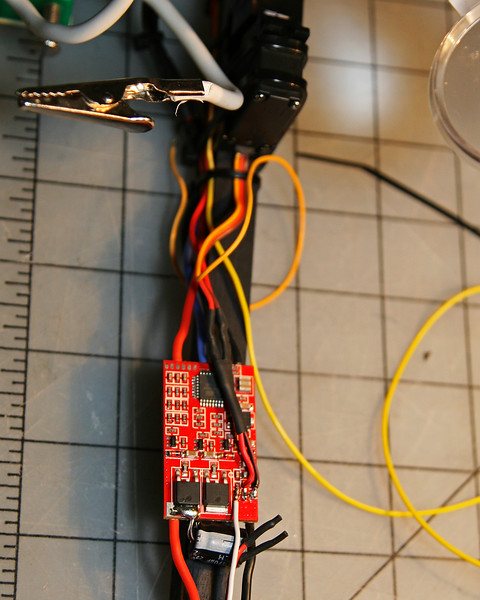
RTFQ 20A Fire Red Esc's (I can't decide if I should use something with One Shot capabilities or not)
MinimOSD
Battery Warning Beeper
Programmable LED Navigation lights.
And finally a Gimbal.
I have already started the project, so I will try to bring you up to speed where I am now.
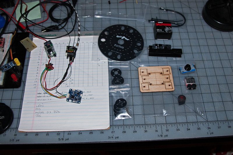
My first hurdle was getting Clean Flight loaded on the FC. It came with Base Flight, which for personal reasons, I will not use. A couple quick searches of the internet showed that I needed to use the ST Demonstrator GUI. (I later found out that I could have skipped this and just used the Chrome CleanFlight Plugin and it would have worked.)
SO I downloaded the ST Demonstrator, but it kept telling me it could not see the Boot Loader. I then realized, I needed to locate the "Boot" jumper. Well, on the Flip32+ Deluxe v5.0 you will need to use a magnifying glass to find it!

Once I soldered a jumper in place, ST Demonstrator did it's thing! Now the Chrome Plugin works perfect.
The next trick was to start getting CleanFlight configured.
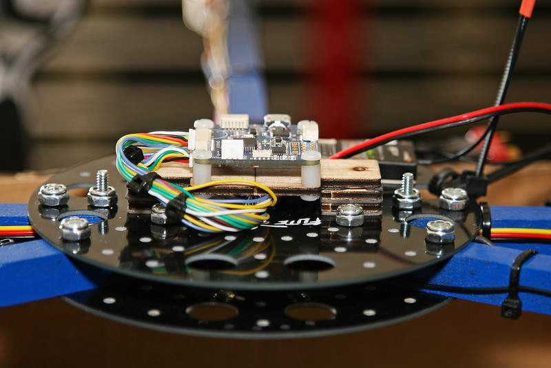
The Flip32+ Deluxe has a 3 pin hole pattern so that Ch.1 can be used for CPPM. I soldered that in and configured my receiver for CPPM. It worked perfect! All 8 channels were registering. But what's this???
What are all these EZ-Connect heades for??
Simple! Use the connecting cables that came with the board to simplify your connections!!
OK, time to un-solder the 3 pin connector I just soldered in. Ch.1 is available on the EZ-Connect. Just follow the wire and push the female pin onto the receiver pin CPPM, and connect the ground pin to the receiver ground pin.
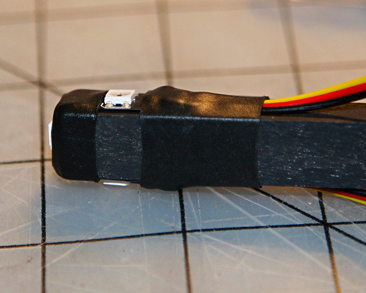
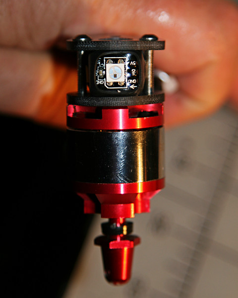
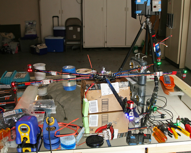
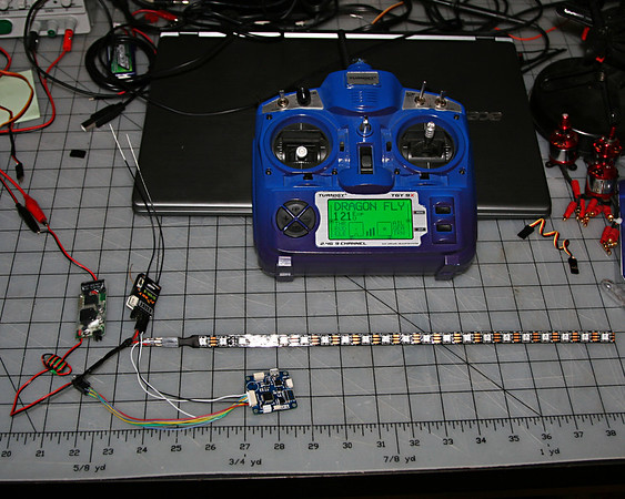
I also will be adding programmable LED lighting for orientation. CleanFlight can handle that, although programming the lights is a bit awkward. The LED Strip connects to Rx input Ch. 5 on this board. So, just take the pin for Ch.5 on the EZ-Connect and put it on the signal pin of the LED strip. BINGO! We have lights!
The last adjustment to CleanFlight was to add a switch to turn the LEDs on and off.
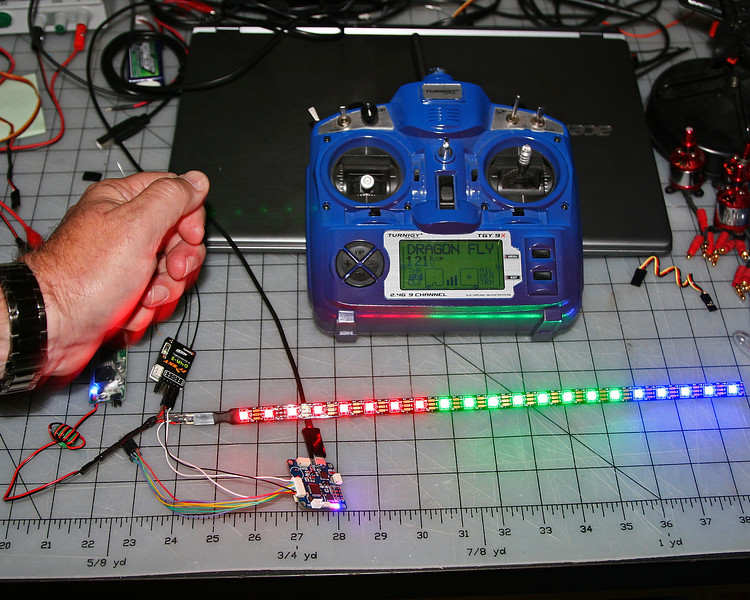
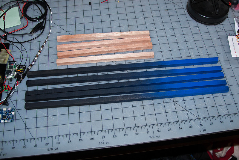
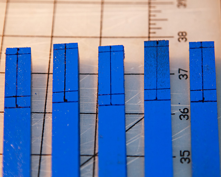
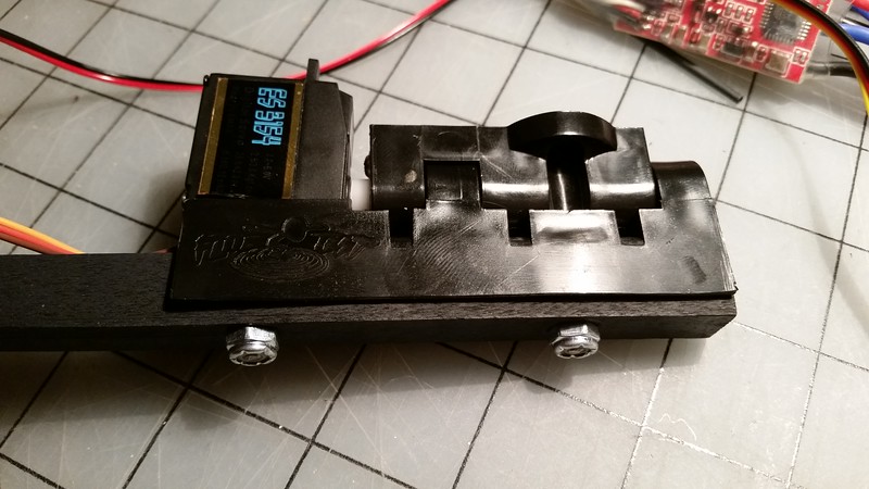
I will be cutting the strip into smaller segments to be placed on the ends of the booms.
This is a continuing project. I'll keep updating this as I go.
Comments, critiques, suggestions are all welcome!
I have long been wanting to build a platform that I know inside and out, yet still feel comfortable enough to put my trust in. I hope you see the humor in that!
I am, among other things, an amateur photographer. I also am a Robotics Mentor and an all around electronics geek.
18 months ago I built my first multi-rotor loosely based on the classic David Windestål Tri design. After retrofitting with a 5.8 GHz 200mw VTx, Bluetooth, Battery Monitor, Flip 1.5, RTFQ Red Special motors and RTFQ 20A Fire Red Esc's, 10" Gem Fans, I really started loving what I had. It flew really well. Although, I have not flown it FPV yet, mostly LOS with the occasional glance at the monitor.

About two weeks ago, I was visiting a friend out in the country (Wilton, Ca.) and was flying around his property. It was quite windy and on one pass, I clipped the edge of a tree and it spun out and hit the grass about 8 feet down. A quick look over didn't reveal any damage, so I put it back in the air. WRONG!!!!
About 100 yards out and 150 ft. up, it threw a prop! Yep, no recovering from that! Every prop was busted. Every arm broken. GoPro kept broadcasting, but had ejected it's SD card in the field..... somewhere.
OK, all that to say, I'm using this "opportunity" to build my next project.
Dragon-Fly Tri
FT ElectroHub
RTFQ Flip32+ Deluxe v5.0
Clean Flight
FrSky D4R-II receiver in CPPM mode.
5X RTFQ Red Special 1000Kv 2212 motors (Can't beet the bang for the buck!)
RTFQ 20A Fire Red Esc's (I can't decide if I should use something with One Shot capabilities or not)
MinimOSD
Battery Warning Beeper
Programmable LED Navigation lights.
And finally a Gimbal.
I have already started the project, so I will try to bring you up to speed where I am now.
My first hurdle was getting Clean Flight loaded on the FC. It came with Base Flight, which for personal reasons, I will not use. A couple quick searches of the internet showed that I needed to use the ST Demonstrator GUI. (I later found out that I could have skipped this and just used the Chrome CleanFlight Plugin and it would have worked.)
SO I downloaded the ST Demonstrator, but it kept telling me it could not see the Boot Loader. I then realized, I needed to locate the "Boot" jumper. Well, on the Flip32+ Deluxe v5.0 you will need to use a magnifying glass to find it!

Once I soldered a jumper in place, ST Demonstrator did it's thing! Now the Chrome Plugin works perfect.
The next trick was to start getting CleanFlight configured.
The Flip32+ Deluxe has a 3 pin hole pattern so that Ch.1 can be used for CPPM. I soldered that in and configured my receiver for CPPM. It worked perfect! All 8 channels were registering. But what's this???
What are all these EZ-Connect heades for??
Simple! Use the connecting cables that came with the board to simplify your connections!!
OK, time to un-solder the 3 pin connector I just soldered in. Ch.1 is available on the EZ-Connect. Just follow the wire and push the female pin onto the receiver pin CPPM, and connect the ground pin to the receiver ground pin.
I also will be adding programmable LED lighting for orientation. CleanFlight can handle that, although programming the lights is a bit awkward. The LED Strip connects to Rx input Ch. 5 on this board. So, just take the pin for Ch.5 on the EZ-Connect and put it on the signal pin of the LED strip. BINGO! We have lights!
The last adjustment to CleanFlight was to add a switch to turn the LEDs on and off.
I will be cutting the strip into smaller segments to be placed on the ends of the booms.
This is a continuing project. I'll keep updating this as I go.
Comments, critiques, suggestions are all welcome!
Last edited: