OrangutangSurfer
Member
A couple notes: this is a long post, my bad, just want to get all the details out. I highly recommend flying the FT Storch (provided it's well powered) on a set of floats it's does it VERY VERY VERY well, at the end is a video of my Storch on some older DIY floats, this float design will function much better but the video shows how well it handles on floats. my test plane was the BJ-J3 cub I love that design it can be found here: BJ-J3 Cub my float maiden was a little windy and my wonky flight was likely due to turbulence from the wind blowing over the trees. I'll report back how how well it flew next flight, but on wheels that plane is a dream to fly. also highly recommended.
I would really love for FT to pick these floats up as a community submitted project but my limited skill in sketch up and other design tools have only produced plans good enough to be reproduced, the lack that beautiful FT title and any specs or measurements, if you can help me correct this (and I've already had offers, Thanks!) please let me know i think FT could make some good use (and probably improvements) and stream line this design for the entire FT community! so if you like them and they work or you find ways to improve them, please post here, i need to go read "how to create an article" and get this design out there.
I'm sorry that I haven't had time to put build pictures together but i thought I could at least post the PDF for the DTFB floats.
The have worked well so far. I can't give a good life span as of yet, i have only had them on the water a few times. However in those few times there is zero de-lamination or breakdown of the floats. I suppose they ought to last a good while.
The floats at printed/built at 100% are approximately 19.5 inches long. They can be scaled to to fit the Storch when printed at 130% and all the parts fit well with the exception of the center former you will need to leave a tad extra on the bottom edge (V hull area) to make up for the fact the foam board is still only 100% in size, other than the center former they can be scaled with out issue to most any size.
Before you begin you will need to figure out what size floats you need. I don't have a formula and if anyone does I'll be happy to edit this. what I have noticed is that floats often extend out slightly in front of the nose of the plane I went about 1" also the step of the float is supposed to be positioned slightly behind the CG of the plane 1/2-1"
So my highly unscientific method (that works so far) is to measure the distance from the CG to 1 1/2" in front of the plane Double that and that is the length of float you need. assuming you mount the step 1/2-1" behind the cg the float should extend slightly in front of the plane, if you google "float set" you'll see this is similar to how nearly every plane is setup.
now that you know how long floats you need, lets scale them... the plans are roughly 20" now use the following equation to determine the scale you need to print them.
Y= length needed
X=Scale (in a percentage)
Y/20 * 100 = X
for example the storch needs approx 26" floats. SO Y=26
26/20 *100 =130
so print these plans at 130% and they will be the right size for the Storch, FYI the step/center former will need to be taller, by extending the area that the hull attaches, explained in more detail below, don't let this deter you it is super easy to do.
DIY DTFB Float set: View attachment Floats_20in_v1.pdf
Instructions.
1.) after all parts are cut out, take the top of the float (the largest piece) and along the two center lines make 50% score cuts. Follow these cuts using a skewer or similar tool and begin to shape the float using the center former as a guide and for test fit. Please note that the former should extend inside the float to the V hull leaving only enough room for the hull to rest on the former and to be flush with the sides of the floats. this will make more sense as we continue. (the only former on the plans is the piece with the circle on it, which is an optional cut out that will be discussed below.
2.) similar to how you would form a FT style wing you will need to run a bead of glue down the 50% cuts. Again, using the former to help keep the shape.
3a.) After gluing both 50% cuts, glue in the former, pay very close attention to the placement, this piece serves a few purposes. first to help give shape to the V hull of the float, second to be a supporting wall to keep water out, third to support the V hull and keep it flush with the sides of the floats when attached, and fourth if you cut out the circle it will allow an optional foam filler to flow the entire length of the float, (to be discussed further later).
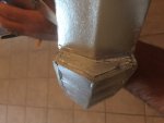
3b.) Former: As mentioned in #1, if you have scaled these floats this is the only piece that may need modification. if you have scaled the plans up make this piece taller by making the V hull portion longer, remember you can always cut away extra foam but you can't add to it. It is important that this piece extends the down the side of the float until it is approximately one foam board width from the bottom side of the float, I hope this is more obvious as you try to test fit the pieces but if anything is misunderstood please post and I will do my best to make corrections. You can see in the pictures below where this former meets the hull, when scaling the plans up it will need to be cut to accommodate the V hull, when scaling the plans down it will need to be trimmed to allow the V hull to fit flush.
4.) the long skinny curved cutouts on the plans are additional support or guide pieces for the front Hull of the float. There is only one requirement when attaching these inside. they must be a form board width from the bottom edge of the side of the float. These pieces help keep the V Hull from getting pushed inside the float when gluing together. They should scale well and as long as they are glued one foam board width from the bottom they will support the V hull regardless of the scale used. it is Ok to trim these, cut them shorter as long as they provide support for the V hull during the build process they will have served their purpose.
5.) Now you can begin to form the hull, make a 50% score cut down the center, I have found this easier to form by removing the inside paper, but please note the 50% cut is easier to make with the paper still attached. as you pull the V portion together you will note that the edges where the V meets do not fit flush. begin making 45 degree cuts and continue to trim off the foam until the pieces fit nicely together while trying to avoid cutting the outside paper. **Test fit this as you go be make sure you do not OVER CUT the foam. A bead of glue will help seal any odd cuts that may have been made during trimming. by not cutting the paper you will help to keep the V hull straight so it will track through the water better. While test fitting you'll notice that the two areas in front will also need trimmed to fit flush, I have found these easier to do AFTER gluing the center of the hull. Do this by running a bead of glue down the center stopping about 1/2" from the back (to prevent gluing to the former at this time). and place the front hull in place shaping to fit along the former and nicely along the side support pieces. after this has dried continue to trim the front of the hull to fit flush to the front of the float.
5a.) once your front hull is trimmed nicely and test fits well. and you're happy with it's fit, glue it in place. this can be tricky to hold both pieces and not get burned with hot glue, so perform a few test fits pretending to glue it in place and see where your hull wants to stick or needs a little bending to get in to place. create a glue strategy that works just remember once it's in place you can, and probably should, run a bed of glue everywhere there is a paper edge to help seal this off and prevent de-lamination.
6.) the rear hull is very straight forward, make a 50% cut down the center and begin to shape this piece. Unlike the front portion of the hull the back of the hull will sit ON TOP of the sides of the float. if the dimensions of the center former were not widened by mistake there should be enough distance between the back of portion of the float to create a gentle V bend in the rear hull when glued in place. be sure to test fit this prior to gluing. You will likely notice in the center where the rear hull meets the former which is now the step of the float, the rear hull does not fit flush trim off the foam to correct this. then glue in place.
7.) lastly you'll notice there is not a piece to seal the rear of the float, this was mistakenly left off the plans and I appologize, however this is a simple as tracing out the back of the float and cutting out a small piece to seal it up.
NOTE: to a small degree you can use extra hot glue to fill holes and gaps to help seal the float, however this is best done after the initial gluing is done and the first application of glue is dried. afterwards you can go over the entire piece using small drops to fill holes or gaps.
You should now have a complete float, the only questions left to answer are a.) how do we water proof it? and b.) how do we attach it.
to water proof mine I used a healthy coat of oil based minwax making sure that the piece was covered in it's entirety and the paper saturated well, then wiping off any extra. I let this dry approximately 4 hours, gave it a light sand to smooth it out and I then added a coat of spray paint which probably doesn't do a whole lot for water proofing but may seal in some unseen tiny holes and looks cool. You can use the water based method as described in a FT article but my attempt was unsuccessful and this process has worked for me so far.
as with any plane there is the risk of damage occurring and perhaps making a small hole or crack, not to mention the holes that may be created to attach the float. any of these could take on water. however it's unlikely you'll be in the water long enough to sink, i suppose there is a possibility. So additionally you can fill the float with "great stuff". it's an expanding foam that is generally used to fill cracks and gaps around the house and can be purchase for less than $4 at your local home improvement store. the circle cut out in the center former was to allow the expansion of the foam throughout the float but i have since learned that it is better to make an additional cut out in the front of the float on the top and spray the foam in from both ends using the center circle to help make sure the float is filled in its entirety. After doing this it will not matter how well "sealed" your floats are because the hardened foam block that will be created inside will unquestionably float and cannot take on water. Please note this stuff is super sticky and very messy and you will likely spray in way more than you needed even if you try not to be prepared to CUT off the foam that will almost certainly expand out of the holes you used to fill it. it may take 24 hours to dry and fully expand. wait until then to cut/trim the excess and then proceed to min wax and paint.
Attaching the floats:
this is left to your creativity, I have a 3D printer file with some mounts a buddy helped design that i will try to attach to this post. My prototypes used zip ties and worked quite well. Depending on the gage of wire used and the sturdiness of the existing landing gear you may need to reinforce the floats further with diagonal braces these can likely be cut to length then zipped and hot glued in place. For bigger heavier planes you may need to develop a stronger mounting system.
Below you can see at the step which is also the former. notice how it supports the V hull and is one foam board length from the bottom edge of the side of the float allowing the front hull to be installed flush with the sides of the float.
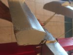
This next picture shows the rear of the float and the piece that is NOT on the plans that will need to be traced out and applied. NOTE: remove the inside paper when gluing this piece in.
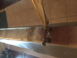
Below shows one option for attaching the floats. I used two zip ties to help provide stability and keep the float from rocking side to side. I cut them about 1/2" long and made test fit holes, once happy i applied a healthy amount of glue enough to be forced a little in side the float this helped attach the zip tie well. I was able to use the existing gear and wheel collar to attach to keep the floats removable. NOTE: because gear is often in various locations in relation to CG on different air frames i would not consider these floats to be swappable, however that doesn't me that they can't be, you can always glue in additional mounts for your different planes. that is up to you
also if you don't need them to be removable you can permanently attach them by gluing some foam squares over the gear directly to the top of the float, this will need to be done BEFORE applying any min wax.
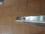
Below is the rear mount. which could have been better with 2 zip ties like the front was... lesson learned, however it did work, and still is.
Front view. Notice that there is no horizontal wire in the front of the floats. This landing gear was ridged enough that it did not require one, however other gear setups might and regardless a horizontal support wire would be of benefit as it will keep the floats from doing the splits in rougher landings.
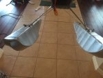
Bottom View:
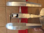
Front of Float: notice the small space between the front hull and top deck of the float, I used additional hot glue to seal that in to prevent taking on water.
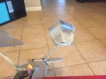
Side view: Notice the lack of diagonal supports. again ridged front gear did not require them but they weren't as stable as i would have liked with out. an option for installing diagonal gear was described above.
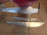
Rear support. in this photo you'll notice the zip ties, I failed to make the rear support wire wide enough to cover the width of the fuse it therefore rocked left and right. it was installed using a skewer and rubber band similar to how a removable FT wing is attached. the zip ties provided a ridged support preventing the rocking of the wire, this may still be needed with a wider wire configuration, i have yet test it because this setup is currently working well.
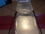
Thanks for reading I hope I've provided enough detail for somebody to build their own.
Please post any completed projects here in the forum.
PS my test platform was the BJ-J3 cub design that can be found by searching "BJ-J3" in the flitetest articles section. I have flown the FT Storch on some other DIY floats and it flies very well with them. give it a try!
VIDEOS:
Floats testing: pay no attention to the flying but note the floats work well!!
Storch on floats:
- Jes
I would really love for FT to pick these floats up as a community submitted project but my limited skill in sketch up and other design tools have only produced plans good enough to be reproduced, the lack that beautiful FT title and any specs or measurements, if you can help me correct this (and I've already had offers, Thanks!) please let me know i think FT could make some good use (and probably improvements) and stream line this design for the entire FT community! so if you like them and they work or you find ways to improve them, please post here, i need to go read "how to create an article" and get this design out there.
I'm sorry that I haven't had time to put build pictures together but i thought I could at least post the PDF for the DTFB floats.
The have worked well so far. I can't give a good life span as of yet, i have only had them on the water a few times. However in those few times there is zero de-lamination or breakdown of the floats. I suppose they ought to last a good while.
The floats at printed/built at 100% are approximately 19.5 inches long. They can be scaled to to fit the Storch when printed at 130% and all the parts fit well with the exception of the center former you will need to leave a tad extra on the bottom edge (V hull area) to make up for the fact the foam board is still only 100% in size, other than the center former they can be scaled with out issue to most any size.
Before you begin you will need to figure out what size floats you need. I don't have a formula and if anyone does I'll be happy to edit this. what I have noticed is that floats often extend out slightly in front of the nose of the plane I went about 1" also the step of the float is supposed to be positioned slightly behind the CG of the plane 1/2-1"
So my highly unscientific method (that works so far) is to measure the distance from the CG to 1 1/2" in front of the plane Double that and that is the length of float you need. assuming you mount the step 1/2-1" behind the cg the float should extend slightly in front of the plane, if you google "float set" you'll see this is similar to how nearly every plane is setup.
now that you know how long floats you need, lets scale them... the plans are roughly 20" now use the following equation to determine the scale you need to print them.
Y= length needed
X=Scale (in a percentage)
Y/20 * 100 = X
for example the storch needs approx 26" floats. SO Y=26
26/20 *100 =130
so print these plans at 130% and they will be the right size for the Storch, FYI the step/center former will need to be taller, by extending the area that the hull attaches, explained in more detail below, don't let this deter you it is super easy to do.
DIY DTFB Float set: View attachment Floats_20in_v1.pdf
Instructions.
1.) after all parts are cut out, take the top of the float (the largest piece) and along the two center lines make 50% score cuts. Follow these cuts using a skewer or similar tool and begin to shape the float using the center former as a guide and for test fit. Please note that the former should extend inside the float to the V hull leaving only enough room for the hull to rest on the former and to be flush with the sides of the floats. this will make more sense as we continue. (the only former on the plans is the piece with the circle on it, which is an optional cut out that will be discussed below.
2.) similar to how you would form a FT style wing you will need to run a bead of glue down the 50% cuts. Again, using the former to help keep the shape.
3a.) After gluing both 50% cuts, glue in the former, pay very close attention to the placement, this piece serves a few purposes. first to help give shape to the V hull of the float, second to be a supporting wall to keep water out, third to support the V hull and keep it flush with the sides of the floats when attached, and fourth if you cut out the circle it will allow an optional foam filler to flow the entire length of the float, (to be discussed further later).
3b.) Former: As mentioned in #1, if you have scaled these floats this is the only piece that may need modification. if you have scaled the plans up make this piece taller by making the V hull portion longer, remember you can always cut away extra foam but you can't add to it. It is important that this piece extends the down the side of the float until it is approximately one foam board width from the bottom side of the float, I hope this is more obvious as you try to test fit the pieces but if anything is misunderstood please post and I will do my best to make corrections. You can see in the pictures below where this former meets the hull, when scaling the plans up it will need to be cut to accommodate the V hull, when scaling the plans down it will need to be trimmed to allow the V hull to fit flush.
4.) the long skinny curved cutouts on the plans are additional support or guide pieces for the front Hull of the float. There is only one requirement when attaching these inside. they must be a form board width from the bottom edge of the side of the float. These pieces help keep the V Hull from getting pushed inside the float when gluing together. They should scale well and as long as they are glued one foam board width from the bottom they will support the V hull regardless of the scale used. it is Ok to trim these, cut them shorter as long as they provide support for the V hull during the build process they will have served their purpose.
5.) Now you can begin to form the hull, make a 50% score cut down the center, I have found this easier to form by removing the inside paper, but please note the 50% cut is easier to make with the paper still attached. as you pull the V portion together you will note that the edges where the V meets do not fit flush. begin making 45 degree cuts and continue to trim off the foam until the pieces fit nicely together while trying to avoid cutting the outside paper. **Test fit this as you go be make sure you do not OVER CUT the foam. A bead of glue will help seal any odd cuts that may have been made during trimming. by not cutting the paper you will help to keep the V hull straight so it will track through the water better. While test fitting you'll notice that the two areas in front will also need trimmed to fit flush, I have found these easier to do AFTER gluing the center of the hull. Do this by running a bead of glue down the center stopping about 1/2" from the back (to prevent gluing to the former at this time). and place the front hull in place shaping to fit along the former and nicely along the side support pieces. after this has dried continue to trim the front of the hull to fit flush to the front of the float.
5a.) once your front hull is trimmed nicely and test fits well. and you're happy with it's fit, glue it in place. this can be tricky to hold both pieces and not get burned with hot glue, so perform a few test fits pretending to glue it in place and see where your hull wants to stick or needs a little bending to get in to place. create a glue strategy that works just remember once it's in place you can, and probably should, run a bed of glue everywhere there is a paper edge to help seal this off and prevent de-lamination.
6.) the rear hull is very straight forward, make a 50% cut down the center and begin to shape this piece. Unlike the front portion of the hull the back of the hull will sit ON TOP of the sides of the float. if the dimensions of the center former were not widened by mistake there should be enough distance between the back of portion of the float to create a gentle V bend in the rear hull when glued in place. be sure to test fit this prior to gluing. You will likely notice in the center where the rear hull meets the former which is now the step of the float, the rear hull does not fit flush trim off the foam to correct this. then glue in place.
7.) lastly you'll notice there is not a piece to seal the rear of the float, this was mistakenly left off the plans and I appologize, however this is a simple as tracing out the back of the float and cutting out a small piece to seal it up.
NOTE: to a small degree you can use extra hot glue to fill holes and gaps to help seal the float, however this is best done after the initial gluing is done and the first application of glue is dried. afterwards you can go over the entire piece using small drops to fill holes or gaps.
You should now have a complete float, the only questions left to answer are a.) how do we water proof it? and b.) how do we attach it.
to water proof mine I used a healthy coat of oil based minwax making sure that the piece was covered in it's entirety and the paper saturated well, then wiping off any extra. I let this dry approximately 4 hours, gave it a light sand to smooth it out and I then added a coat of spray paint which probably doesn't do a whole lot for water proofing but may seal in some unseen tiny holes and looks cool. You can use the water based method as described in a FT article but my attempt was unsuccessful and this process has worked for me so far.
as with any plane there is the risk of damage occurring and perhaps making a small hole or crack, not to mention the holes that may be created to attach the float. any of these could take on water. however it's unlikely you'll be in the water long enough to sink, i suppose there is a possibility. So additionally you can fill the float with "great stuff". it's an expanding foam that is generally used to fill cracks and gaps around the house and can be purchase for less than $4 at your local home improvement store. the circle cut out in the center former was to allow the expansion of the foam throughout the float but i have since learned that it is better to make an additional cut out in the front of the float on the top and spray the foam in from both ends using the center circle to help make sure the float is filled in its entirety. After doing this it will not matter how well "sealed" your floats are because the hardened foam block that will be created inside will unquestionably float and cannot take on water. Please note this stuff is super sticky and very messy and you will likely spray in way more than you needed even if you try not to be prepared to CUT off the foam that will almost certainly expand out of the holes you used to fill it. it may take 24 hours to dry and fully expand. wait until then to cut/trim the excess and then proceed to min wax and paint.
Attaching the floats:
this is left to your creativity, I have a 3D printer file with some mounts a buddy helped design that i will try to attach to this post. My prototypes used zip ties and worked quite well. Depending on the gage of wire used and the sturdiness of the existing landing gear you may need to reinforce the floats further with diagonal braces these can likely be cut to length then zipped and hot glued in place. For bigger heavier planes you may need to develop a stronger mounting system.
Below you can see at the step which is also the former. notice how it supports the V hull and is one foam board length from the bottom edge of the side of the float allowing the front hull to be installed flush with the sides of the float.

This next picture shows the rear of the float and the piece that is NOT on the plans that will need to be traced out and applied. NOTE: remove the inside paper when gluing this piece in.

Below shows one option for attaching the floats. I used two zip ties to help provide stability and keep the float from rocking side to side. I cut them about 1/2" long and made test fit holes, once happy i applied a healthy amount of glue enough to be forced a little in side the float this helped attach the zip tie well. I was able to use the existing gear and wheel collar to attach to keep the floats removable. NOTE: because gear is often in various locations in relation to CG on different air frames i would not consider these floats to be swappable, however that doesn't me that they can't be, you can always glue in additional mounts for your different planes. that is up to you
also if you don't need them to be removable you can permanently attach them by gluing some foam squares over the gear directly to the top of the float, this will need to be done BEFORE applying any min wax.

Below is the rear mount. which could have been better with 2 zip ties like the front was... lesson learned, however it did work, and still is.

Front view. Notice that there is no horizontal wire in the front of the floats. This landing gear was ridged enough that it did not require one, however other gear setups might and regardless a horizontal support wire would be of benefit as it will keep the floats from doing the splits in rougher landings.

Bottom View:

Front of Float: notice the small space between the front hull and top deck of the float, I used additional hot glue to seal that in to prevent taking on water.

Side view: Notice the lack of diagonal supports. again ridged front gear did not require them but they weren't as stable as i would have liked with out. an option for installing diagonal gear was described above.

Rear support. in this photo you'll notice the zip ties, I failed to make the rear support wire wide enough to cover the width of the fuse it therefore rocked left and right. it was installed using a skewer and rubber band similar to how a removable FT wing is attached. the zip ties provided a ridged support preventing the rocking of the wire, this may still be needed with a wider wire configuration, i have yet test it because this setup is currently working well.

Thanks for reading I hope I've provided enough detail for somebody to build their own.
Please post any completed projects here in the forum.
PS my test platform was the BJ-J3 cub design that can be found by searching "BJ-J3" in the flitetest articles section. I have flown the FT Storch on some other DIY floats and it flies very well with them. give it a try!
VIDEOS:
Floats testing: pay no attention to the flying but note the floats work well!!
Storch on floats:
- Jes
