
You are using an out of date browser. It may not display this or other websites correctly.
You should upgrade or use an alternative browser.
You should upgrade or use an alternative browser.
FTFC20 Floating Kidney 1947 by Vimana89
- Thread starter Vimana89
- Start date


Vimana89
Legendary member
Prototyping and Test Flying Log
*Drew up a quick sketch called the "Floating Kobra" that utilizes a high mounted pusher setup.
* Changed design from a high mounted pusher(as in the sketch #1 "Kobra") to a tractor setup.
Prototype 1 "Kobra" Floating Kidney (Tractor Version)
Electronics/Props
motor: FT Radial 1806
ESC: FT 20A
prop: Raycorp 5x3x2
Servos: 2x 9g bulk
Extra: ?x Servo extension cables
TX/RX: FS IA6
Battery: Tattu 1300 mAh 45c 3s 11.1 V(850 with full nose)
Size Range
16" wing span "mighty mini"
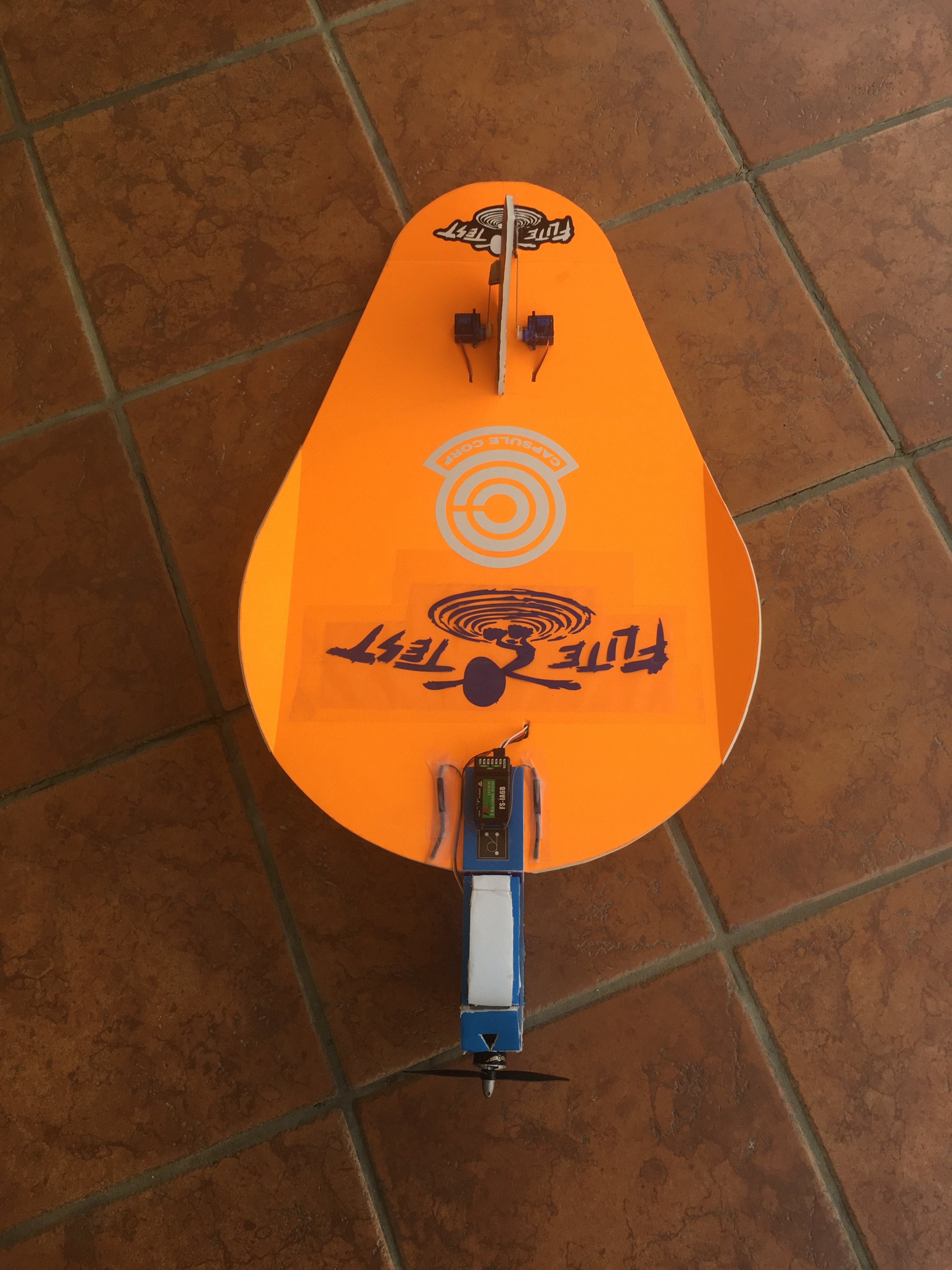
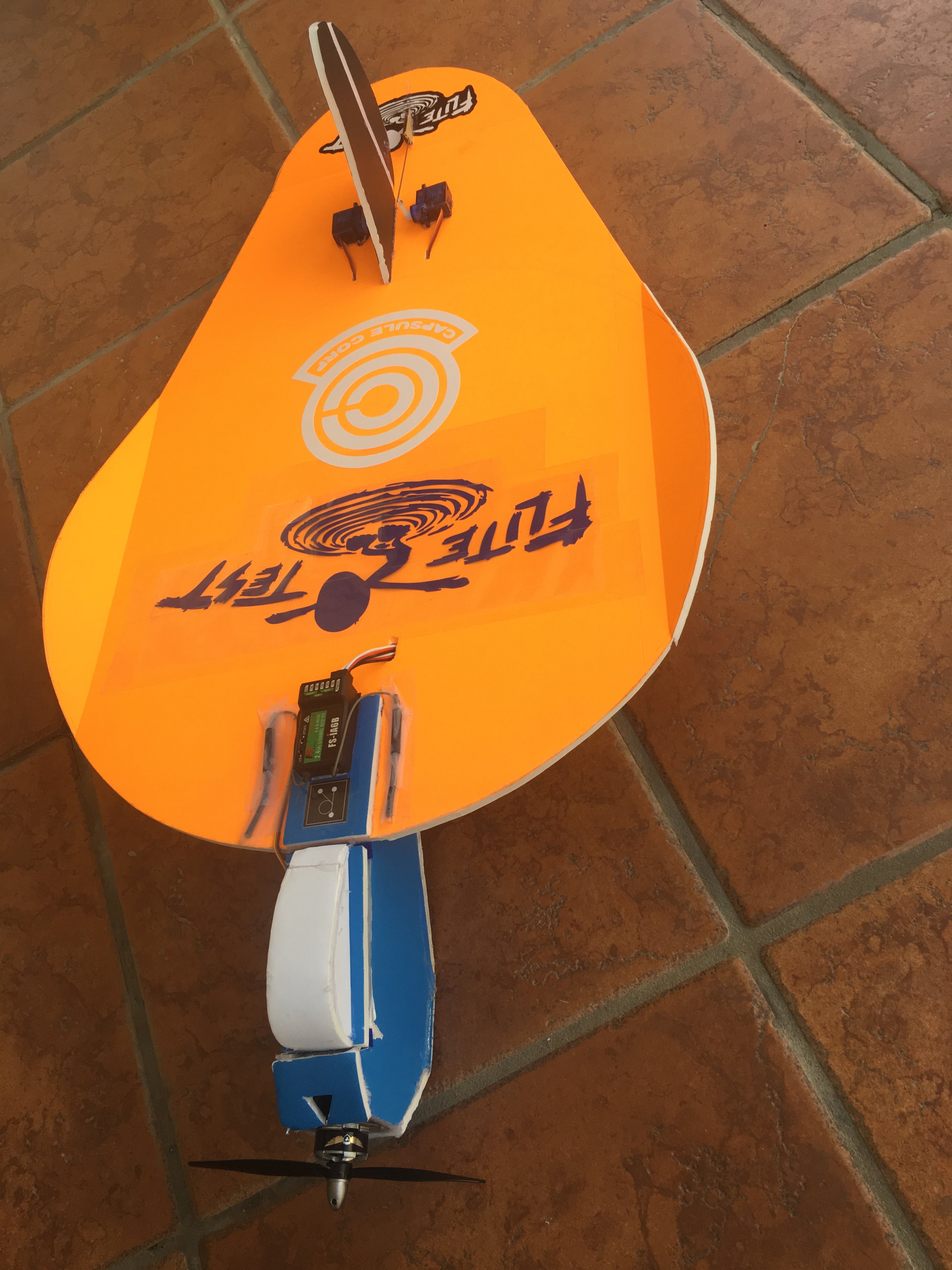
Design/Build
Simple "bare bones" prototype with no box fuselage or folds. A basic two piece tractor motor mount sits atop the wing and a one layer spine runs along the underside up to the elevator hinge. Electronics secured topside with Velcro, packing tape, and scotch tape. The main design differences/changes from the original balsa plan are the top-mounted snub-nose on my prototype, and the positioning of the vertical stabilizer and rudder before a single elevator, whereas the original had a split elevator with a VS that ran through and stopped just behind the elevator. A 1300 battery was used to bring CG forward to acceptable range, and because the design has very low wing loading even at a smaller 16" size.
Result
Success! Flew well on maiden, handles well, lands in one piece. Power is good and not lacking, run time is 30 minutes on one battery charge, and electronics are cool on landing.
Prototype 1 Full Nose Upgrade
Changes
Motor mount removed. Full A fold box nose that closely replicates the original 1947 glider's nose added and battery and CG moved up from slightly tail heavy to a bit nose heavy, using an 850 rather than 1300 battery.
Result
1.)Maidened in a small gap in stronger winds with some wind interference still.Plane flew successfully and was controllable. Slight nose down tendency and dip from CG and/or thrust angle that should clear up with a little sub trim. Seeming slight increase in stability and noticeable improvement in penetration. Will trim and test further with no wind interference.
2.)Further testing shows the design to have benefitted more than just aesthetically from the addition of the full nose. The CG is brought forward to eliminate tail heaviness, but now it may be just a hair nose heavy, which is preferable, but further tweaking may be required. Glide ratio is outstanding, simulated dead stick landings are fairly easy. Looping is also not difficult.
PT 2/1.0 Version Attempt 1
Changes From Prototype 1:
1.) increased wingtip dihedral angle to 30 degrees for more noticeable auto-leveling
2.)flat rather than curved backplate on the nose box, for flush battery fit
3.)two layer spine for extra durability and better grip for hand launch
4.) more rounded elevator to more closely resemble original glider
5.) add a cockpit on top of the nose box hatch for aesthetics and to act as a grip for popping the hatch on and off
6.) VS that more closely replicates that of the original glider while maintaining its position afore of the elevator, as in my prototype rather than the original
7.) cleaner wiring and less clutter on the topside of the wing
8.) very slightly higher sweep and wing chord length than original and prototype(in an attempt to add more elevator authority, increase symmetry of air flow, and exaggerate the profile just a bit more
Result
1.)Successful maiden flight with improvements in elevator authority, looping ability and ease, and auto-leveling over prototype 1. The increase in dihedral on the wing tips to 30 degrees, which provides pretty much no-brainer auto leveling at this point, also added slight Dutch roll here and there, but nothing extreme. The glide ratio seems about the same, but could possibly have lost just a bit by increasing dihedral angle and changing the profile of the wing ever so slightly. I'll need to test this and other things further to see if I want this exact wing on the 1.0 version and plan.
2.) Further testing and observations seem to show, if anything, a slight improvement or no noticeable change in glide ratio, which is definitely a plus. I experimented with multiple different props, all of which performed well but had different pluses and minuses, so I'll be including my testing experiences and observations about each one, and comparing them.
3.) I'm fully satisfied with this version's performance, and have decided to use it as the 1.0 model for the plans.
Prop Testing
All of my testing was done with Raycorp/Gemfan brand props. Propellers of the same specifications can vary a bit in performance from brand to brand. I do not have hard figures, like thrust and watts. I will be getting a watt meter and stuff in the future. My data is based on observations from actual hands-on flight testing of how these propellers perform and handle on this design.
1.)Raycorp 5x3x2: The most efficient, coolest running option that is the least demanding on the system. Plenty of power, but no excess. More than enough for standard maneuvers, some loops at high throttle, decent climb and punch out, and some very basic, modest high alpha.
2.) Raycorp 5x4.5x2 King Kong Bullnose: Loads of thrust to spare, very linear throttle, nice quiet hum. Improved punch out, high alpha, and speed envelope. Best top speed and acceleration. Runs warm and a bit inefficient, but hasn't caused a problem.
3.) Raycorp 5x4x2: The most well rounded option; the "Jack of all trades", so to speak. Similar power and performance to the Bullnose, minus a hair of excess thrust. Gets a tiny bit warm, but overall very efficient.
4.) Raycorp/Gemfan 5x3x3: Best vert/climb/ punch out, best high alpha, best(also easiest and slowest) loops. Best speed envelope and slowest slow flight, with good top end speed and acceleration. Runs very quiet and stays cool. Being a three blade, this is less efficient than a two bladed prop, but it is definitely the best option for aerobatics and slow flight.
*Drew up a quick sketch called the "Floating Kobra" that utilizes a high mounted pusher setup.
* Changed design from a high mounted pusher(as in the sketch #1 "Kobra") to a tractor setup.
Prototype 1 "Kobra" Floating Kidney (Tractor Version)
Electronics/Props
motor: FT Radial 1806
ESC: FT 20A
prop: Raycorp 5x3x2
Servos: 2x 9g bulk
Extra: ?x Servo extension cables
TX/RX: FS IA6
Battery: Tattu 1300 mAh 45c 3s 11.1 V(850 with full nose)
Size Range
16" wing span "mighty mini"
Design/Build
Simple "bare bones" prototype with no box fuselage or folds. A basic two piece tractor motor mount sits atop the wing and a one layer spine runs along the underside up to the elevator hinge. Electronics secured topside with Velcro, packing tape, and scotch tape. The main design differences/changes from the original balsa plan are the top-mounted snub-nose on my prototype, and the positioning of the vertical stabilizer and rudder before a single elevator, whereas the original had a split elevator with a VS that ran through and stopped just behind the elevator. A 1300 battery was used to bring CG forward to acceptable range, and because the design has very low wing loading even at a smaller 16" size.
Result
Success! Flew well on maiden, handles well, lands in one piece. Power is good and not lacking, run time is 30 minutes on one battery charge, and electronics are cool on landing.
Prototype 1 Full Nose Upgrade
Changes
Motor mount removed. Full A fold box nose that closely replicates the original 1947 glider's nose added and battery and CG moved up from slightly tail heavy to a bit nose heavy, using an 850 rather than 1300 battery.
Result
1.)Maidened in a small gap in stronger winds with some wind interference still.Plane flew successfully and was controllable. Slight nose down tendency and dip from CG and/or thrust angle that should clear up with a little sub trim. Seeming slight increase in stability and noticeable improvement in penetration. Will trim and test further with no wind interference.
2.)Further testing shows the design to have benefitted more than just aesthetically from the addition of the full nose. The CG is brought forward to eliminate tail heaviness, but now it may be just a hair nose heavy, which is preferable, but further tweaking may be required. Glide ratio is outstanding, simulated dead stick landings are fairly easy. Looping is also not difficult.
PT 2/1.0 Version Attempt 1
Changes From Prototype 1:
1.) increased wingtip dihedral angle to 30 degrees for more noticeable auto-leveling
2.)flat rather than curved backplate on the nose box, for flush battery fit
3.)two layer spine for extra durability and better grip for hand launch
4.) more rounded elevator to more closely resemble original glider
5.) add a cockpit on top of the nose box hatch for aesthetics and to act as a grip for popping the hatch on and off
6.) VS that more closely replicates that of the original glider while maintaining its position afore of the elevator, as in my prototype rather than the original
7.) cleaner wiring and less clutter on the topside of the wing
8.) very slightly higher sweep and wing chord length than original and prototype(in an attempt to add more elevator authority, increase symmetry of air flow, and exaggerate the profile just a bit more
Result
1.)Successful maiden flight with improvements in elevator authority, looping ability and ease, and auto-leveling over prototype 1. The increase in dihedral on the wing tips to 30 degrees, which provides pretty much no-brainer auto leveling at this point, also added slight Dutch roll here and there, but nothing extreme. The glide ratio seems about the same, but could possibly have lost just a bit by increasing dihedral angle and changing the profile of the wing ever so slightly. I'll need to test this and other things further to see if I want this exact wing on the 1.0 version and plan.
2.) Further testing and observations seem to show, if anything, a slight improvement or no noticeable change in glide ratio, which is definitely a plus. I experimented with multiple different props, all of which performed well but had different pluses and minuses, so I'll be including my testing experiences and observations about each one, and comparing them.
3.) I'm fully satisfied with this version's performance, and have decided to use it as the 1.0 model for the plans.
Prop Testing
All of my testing was done with Raycorp/Gemfan brand props. Propellers of the same specifications can vary a bit in performance from brand to brand. I do not have hard figures, like thrust and watts. I will be getting a watt meter and stuff in the future. My data is based on observations from actual hands-on flight testing of how these propellers perform and handle on this design.
1.)Raycorp 5x3x2: The most efficient, coolest running option that is the least demanding on the system. Plenty of power, but no excess. More than enough for standard maneuvers, some loops at high throttle, decent climb and punch out, and some very basic, modest high alpha.
2.) Raycorp 5x4.5x2 King Kong Bullnose: Loads of thrust to spare, very linear throttle, nice quiet hum. Improved punch out, high alpha, and speed envelope. Best top speed and acceleration. Runs warm and a bit inefficient, but hasn't caused a problem.
3.) Raycorp 5x4x2: The most well rounded option; the "Jack of all trades", so to speak. Similar power and performance to the Bullnose, minus a hair of excess thrust. Gets a tiny bit warm, but overall very efficient.
4.) Raycorp/Gemfan 5x3x3: Best vert/climb/ punch out, best high alpha, best(also easiest and slowest) loops. Best speed envelope and slowest slow flight, with good top end speed and acceleration. Runs very quiet and stays cool. Being a three blade, this is less efficient than a two bladed prop, but it is definitely the best option for aerobatics and slow flight.
Last edited:
Vimana89
Legendary member
Specs, Parts List, and Build Guide(Rough draft, no pics)
Specs
parts list
*Motor: FT Radial 1806 2280kV
*ESC: FT 20A
*TX/RX
*Prop: 5x3x2(efficiency), 5x4x2(well rounded performance),5x4.5x2 Bullnose(thrust/speed/power), 5x3x3(high alpha, best slow fly and biggest speed envelope with good top speed, aerobatics)
*Servos: 2x 9g(or 5g if you prefer)
*Extra: 2x servo extension cable
FT Techniques Employed: A fold( one small segment of the nose box), paper removal and curving(two small front plates on the nose box)
Vimana89 Techniques and Methods Employed: two layer spine(for planes that only have a nose box/ nacelle fuselage rather than a full box, and also have a one layer wing, my two layer spines provide structural support and a good launching grip. The spine runs along the underside of the wing and keys in to the nose box.) Velcro hatch(Skewer holes annoy me, so I'm working on hatches that open and close only with Velcro. This design features one that comes completely on and off with no hinge.)Vimana89 style hand held dihedral gauge(The gauge I will provide is not the usual style that sits on a surface like a table or work bench. It is well suited to smaller and/or low aspect wings. The wing is held in one hand and the other hand holds the gauge against the crack while the glue sets, allowing the builder to hold it fully steady for quick and easy dihedrals requiring no surface and possibility of the gauges falling out from underneath or anything annoying like that.)
Building from Printed Plans
1.)prep: If you prefer to cut out all pieces before assembly, do this now. Otherwise, start by cutting out the wing and dihedral gauge.
2.) wing: Take the wing blank, and make the score cuts to crack your dihedrals and elevator. Crack the elevator, and cut and/or sand your bevel. Reinforce as desired with tape, glue, etc. Your elevator should be a complete and functional hinge, ready for linkages. Crack the dihedrals, and set them one at a time using glue and the provided gauge. My gauge is different than some in that it is held in one hand while the wing is held in the other, rather than sitting on a surface. After the elevator and dihedrals are ready, cut out the tab slots in the wing for the vertical stabilizer(x1, rear), and the nose box(x4, front). Your wing is now complete. Set it aside.
3.) nose box/fuselage: Cut this piece, the corresponding plates, and the two piece motor mount out if you have not already. Score cuts and remove foam as indicated for the small A fold at the bottom of the box. Glue and set your A fold. Apply non-curved plates(back plates) to the fuselage. Apply two-piece motor mount to firewall, and mount the motor if it isn't already attached to the firewall. Glue the sides of the two-piece mount, and fit it into the front of the nose at desired thrust angle. Once the motor and mount are in place at the desired thrust angle, remove paper from and curve the top and bottom front plates. Apply these plates, and either before or after, cut your desired cooling/venting holes. You should now have a mostly complete nose box just awaiting the top hatch and cockpit. Set this aside for now.
4.) Vertical Stabilizer: Cut this part out if you have not yet done so. Score and crack the rudder, cut/sand the bevel, and reinforce with tape, glue, etc. as desired. You should have a complete vertical stabilizer with functioning rudder hinge, reinforced, finished, and awaiting linkages. Put this aside.
5.) Spine: Cut out the two layers of the spine if not done already, and glue them one atop the other into one piece, as sturdy as you can manage without overdoing the glue. Your spine is complete and can be set aside until it is time for assembly.
6.) Air Frame Assembly: Start by mounting the VS/Rudder to the wing, making sure it is flush at a 90 degree angle. Next, mount the nose box, making sure everything lines up right. remove the paper from one side of the top plate and apply it over the tabs/slots that attack the nose to the wing. This is for both aesthetics and extra strength. Finally, apply the spine, using enough but not too much glue, especially around the sides of the key, and keying the front part of the spine into the back of the underside of the nose box as far as the key reaches until all corners fit flush. Make sure your spine is aligned dead center and not skewed at an angle before gluing down completely.
7.)Linkages and Electronics: Install linkages and electronics as desired. The nose box really only has enough room for the battery and ESC, so the receiver will have to be mounted some place else, such as the top of the wing. Servo cables can the through-wired and taped along the length of the spine. When everything is in place, and the only thing missing from the plane is the top hatch and cockpit, test electronics and get all of your sub trim and transmitter settings set up the way you want them for maiden. The plane should now be airworthy and ready to test, aside from missing the top hatch.
8.) Top hatch: Install the two small attachment surfaces and Velcro strips in the nose box. If you haven't already, cut out the top hatch and bubble cockpit pieces. Assemble the cockpit by removing paper from and curving the top plate, and then gluing that to the sides. glue this directly along the center of the top hatch. Add opposite Velcro strips to the bottom of the hatch as indicated. You should now have a cockpit and top hatch which pop on and off just with Velcro! It is a good idea to actually glue down the Velcro strips, especially the ones on the nose box side, as they can start to peel.
Congratulations, your Floating Kidney should be ready to fly!
Last edited:

Vimana89
Legendary member
Yup. Flies a whole lot like a Nutball with subtle differences. It's got more wing area and lower loading for one since it's kinda "stretched". This allows a massive battery to work well and it brings the CG up. Overall, a super fun plane that will be easy for people to make and be an extremely efficient park flyer.
Vimana89
Legendary member
Video section is updated with some footage from the new build! I still need more flight testing to see if I want this to be the 1.0 release version. I'm satisfied with the nose box and new bubble cockpit, and will be drawing up that part of the plan very soon. I will need to fly more to see if the wing and vertical stabilizer are optimized where I want them. Last decals for this build version will be arriving shortly.
I'll be filling in other information related to the challenge soon, but my prototyping log and video log are up to date. If anyone has any questions or suggestions regarding the design, let me know! I could always use a little input from more experienced builders and pilots on things like how much dihedral angle is optimal, and about how the size, shape, and placement of my vertical stabilizer impacts flight characteristics. I mean, the plane flies pretty good already, but it's always possible there's something I could be missing that somebody else will notice that could give me a significant improvement for a very small adjustment here or there.
I'll be filling in other information related to the challenge soon, but my prototyping log and video log are up to date. If anyone has any questions or suggestions regarding the design, let me know! I could always use a little input from more experienced builders and pilots on things like how much dihedral angle is optimal, and about how the size, shape, and placement of my vertical stabilizer impacts flight characteristics. I mean, the plane flies pretty good already, but it's always possible there's something I could be missing that somebody else will notice that could give me a significant improvement for a very small adjustment here or there.
Last edited:
Vimana89
Legendary member
Did more flying this morning, might get another chance today, maybe not. Loving the 1.0, its about as good as I think I can get it. The Dutch roll only really becomes noticeable with wind, and these types of planes aren't big fans of wind to begin with. A fair trade off for very good auto leveling, but maybe I'll include two different angles of dihedral gauge for an option. More footage to come, but the build guide rough draft is up! I though about if I were assembling this from a printed plan, what would be the easiest and most efficient procedure, so I have all the steps written out.
Vimana89
Legendary member
Final decal came. By applying that, I realized I probably did the FT one wrong. I didn't know you had to peel off the clear par(assuming it's one of those) and I just taped it down so that part would stop peeling. A little goofy but still looks ok, I know for next time.
Attachments


Vimana89
Legendary member
Further flight testing shows, if anything, an improvement rather than a loss of glide ratio which is very good👍. I managed a couple smooth simulated dead-stick landings, and some gliding and restarting throttle in air. The plane handles awesome, turns smooth for RET, and is very simple to fly. This thing just wants to stay in the air, it's very hard to crash, and it is also very maneuverable. I tried both 5x3x2 and 5x4.5x2 bullnose props. 5x3x2 is a good baseline and works well but could use a little oomph. The bullnose are smoother and more powerful, but run a bit hot. I'll be testing 5x4x2 and 5x3x3 to see how I like those next after I order some.
Vimana89
Legendary member
Think they mixed up my order and sent two packs of 5x3x3 instead of one of 5x4x2 No big deal. These Gemfan 5x3x3 are super thin and flimsy, and on a couple occasions have made a really funky discordant noise when cranked all the way to full throttle. Could be their flimsiness, or could actually just be the air blowing into the venting holes. In flight they held up fine. These are the way to go for high alpha and a bigger speed envelope. I can do slower loops and flips, fly slower in general, and much better high alpha. This does high alpha almost as good as my V Sliver with the three blade prop👍.
Vimana89
Legendary member
Found the 5x4x2 hidden in the bottom of the envelope before tossing it, thankfully. These work very well, sort of a well-rounded, jack of all trades. I have picked out all the bits of footage I want to use for a good compilation that overs all the bases and showcases all of the plane's ability. There's bits with every different prop I tested and maneuver I tried. I have them sorted out, I just need to edit and compile them. I have some measurements and a template set aside to begin hand drawing the plans. I still have to finish filling in some more info related to the challenge.
The Floating Kidney is now 1.0 ready! Minor variations, improvements, and experimentation may come later, but the current(orange, blue, and white) model performs to my satisfaction, and will be the version used for the plans.
The Floating Kidney is now 1.0 ready! Minor variations, improvements, and experimentation may come later, but the current(orange, blue, and white) model performs to my satisfaction, and will be the version used for the plans.
Vimana89
Legendary member
Tried with some fancy landing gear meant for some form of Cub. The way I mounted it was sort of a jury-rigged sloppy fashion. It holds up, but the mounting method isn't something I'd officially release. What this shows me is that the plane still flies well with fixed landing gear, and benefits from it on landings as well. This design will work well as either a belly lander or with fixed gear, but for now, I'll leave the method of mounting any desired landing gear up to the builder.
Attachments


Last edited:
Vimana89
Legendary member
Tons of video footage to sort through of this one, and most of it is very good, so I have to sit down and condense just the best. I should have that up within in the next couple days here as I take a short break from building, and I should be started drawing up plans soon too.
Vimana89
Legendary member
Newest flight compilation is up under videos! Unfortunately, I'm pretty sure I lost footage of it flying and landing with the jury-rigged cub landing gear, because that was on my action cam, which I recently lost. I may have tucked it away somewhere on my PC, I'll look around. Thankfully, most of the good recent flight footage I had collected was saved to my desktop PC. Work starting soon on plans!
Also, although this version currently uses 3s, I have a feeling that performance could possibly be even better with 2s if the plane could be balanced, maybe with lighter servos and stuff. The biggest improvement would probably be the already awesome glide ratio, and the high alpha would benefit noticeably too I may have to try yet another version before finalizing, or add a side note to the plans and build guide for options relating to 2s. Either way, the current 3s is already very nice.
Also, although this version currently uses 3s, I have a feeling that performance could possibly be even better with 2s if the plane could be balanced, maybe with lighter servos and stuff. The biggest improvement would probably be the already awesome glide ratio, and the high alpha would benefit noticeably too I may have to try yet another version before finalizing, or add a side note to the plans and build guide for options relating to 2s. Either way, the current 3s is already very nice.
Vimana89
Legendary member
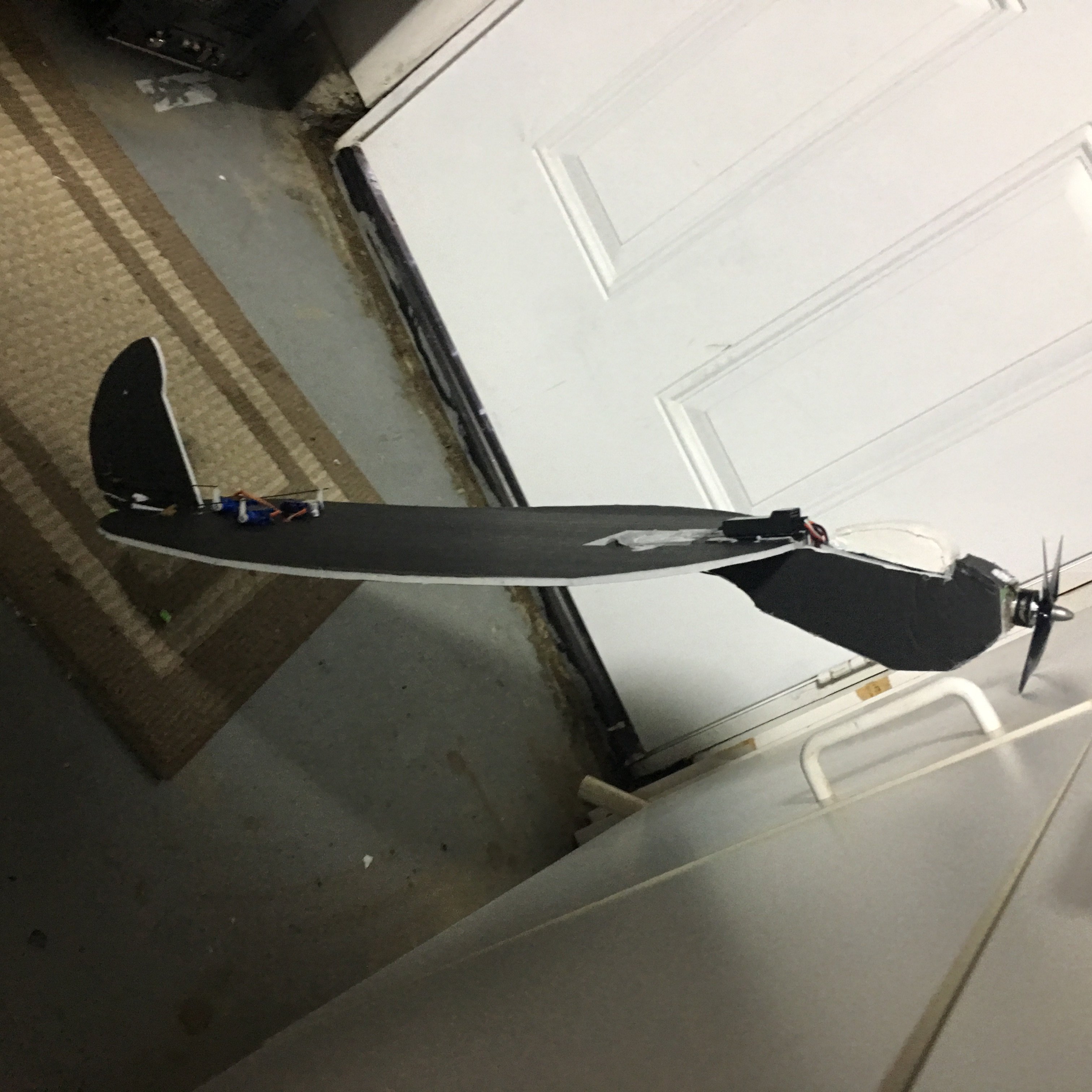
I will need some proper pics of the newest version, but prototype 2 will not be the 1.0 release. The new third prototype is a full 4ch plane with elevons and rudder, and matches the profile of the original glider almost perfectly. It also features a sleeker B fold nose box. The most recent flight footage of the v3/1.o is up in the video section, although it has already been posted on another thread.
I have recently crashed the v3/1.0 and busted the motor mount, which is an easy fix. This seems to be my inexperience combining rudder with elevons rather than a design flaw. This 4ch version is a bit more challenging, but ultimately more capable and rewarding platform that more closely mirrors the original glider. The glide ratio is still exactly the same as previous versions if not better than ever, and axial rolls and cleaner banks are now possible with elevons, though dihedral wingtips have been dialed down to a very shallow angle, so there is less auto leveling. High alpha capability is still the same, and rudder is still there to provide the same level of control as RET, but more precise with elevons too.
This is an awesome plane, and Nutball and Flyer fans won't be disappointed in in a lot of familiar characteristics, but with a jump to elevons and 4ch for full roll capability and the design's extraordinary glide ratio will be a big plus too.


Similar threads
- Replies
- 98
- Views
- 13K
- Replies
- 5
- Views
- 1K
- Replies
- 10
- Views
- 2K
- Replies
- 26
- Views
- 3K