Great Planes J3 Cub

speedbirdted

Legendary member
Went over with the plug with 3 coats of finishing resin, sanded in between. Last coat was wet sanded, just to see how ridiculously smooth I could get it for giggles. Here it is, but I forgot to clean the residue off, so it still looks kinda dull, and not good for the camera :cautious:

P_20200906_231408.jpg


I wanted to kind of paint it in plaster to make the female mold but I quickly determined it didn't dry fast enough and would all just drip off. So, I made this little container to put the plaster in and then put the plug in the plaster.

P_20200907_000851.jpg


Unfortunately I did not have enough plaster to put the whole plug all the way in. It came up about 1/2 an inch short, which theoretically should not be a problem as I cut the plug a little long anyway. However if it is a problem I can reuse the plug as a negative mold instead - that way I would put the glass cloth directly on the plug using release wax to prevent it from just sticking to the plug permanently. Now to wait for the plaster to dry out...

P_20200907_003258 (1).jpg
 

speedbirdted

Legendary member
In conclusion: The plaster didn't work. It turns out being 1/2 inch short is much larger of a problem than I anticipated. So I guess I have to do this the other way...

Started by putting a few coats of release wax on the plug itself. You can just use as much as you possibly can - any area where the resin can directly contact the plug will ruin both the glass and the plug. I don't want that, obviously. Then I waited for the wax to dry then went over it with a coating of resin. I used less hardener as I wanted as much cure time as possible, for reasons that will become clear shortly.

I wanted to cover the whole cowl with one piece of glass; however, even though the fabric is pretty stretchable, it isn't quite enough to be able to contour to the cowling perfectly. So, I did it with five pieces of glass instead. This is my first time doing a fiberglass layup by hand in several years, so it's pretty rough, but it's not really hard.

P_20200908_164337.jpg


All pieces installed, now waiting to cure. I will go over it with three, maybe four more layers of glass. That should make it more than strong enough.

P_20200908_165113.jpg
 

speedbirdted

Legendary member
Coats 2 and 3 of glass applied today. No reason for pictures, it looks exactly the same anyway. I think I'll do 4 total...

I've got a slight dilemma now... from the few test plugs I glassed to determine whether applying glass to the plug directly would even work, I had to cut the glass to get it off without breaking it into random shards or causing huge cracks. This can actually be done in a way that doesn't require the cowl to be glued back together afterwards as I want to make a 2 piece cowling. However - this means I need to know exactly where to cut the cowling, before I have either an engine to figure out where to cut the holes or the ability to even put the cowling on the plane at all. This is obviously kinda difficult. The other option is I just cut it in some random location. This is good because I can cut it in such a way that the cowling will come off the mold better. Sure I would have to glue it back together after but if I do it right it shouldn't look any different externally.
 

speedbirdted

Legendary member
Cut the cowl and popped it off the mold today. Overall I'm very happy with how this came out. Hell, the plug even survived intact! So if I end up smashing this one I can build another ;) It's a little bit light on resin in a few areas resulting in some flimsiness but I will add some reinforcement on the interior and some extra resin on the outside. You can see a small tear in the bottom half - I probably should have cut it down the middle but it was too lazy. Shouldn't be a hard fix anyhow. I'm going to go over it with a coat of primer and then spot putty to get it really smooth for painting. The edges are still pretty rough - this is not the final cut, it's just to get the excess glass off.

P_20200909_224925.jpg


I'm quite happy with the fit and shape. I thought it would be a little wide but it's actually fine. I will add the tabs on the inside to screw the cowling together at some point. Either that or little pegs to use clips.

P_20200909_225624.jpg
 
Last edited:

speedbirdted

Legendary member
Not by that much. It still needs to overlap to a degree to be attached to the fuselage. The two cowl halves will not overlap with one another; that's why tabs are being added.
 
Last edited:

speedbirdted

Legendary member
Added a couple more layers of glass on the inside of the nose of both pieces. Most of the weak area is here. I believe it was caused by the resin running downhill as the glass was laid up with the cowl pointed upwards, causing a lack of resin in that area of the cowl. I let it cure with the pieces in this position to keep the resin in this area.

P_20200911_001235.jpg
 

speedbirdted

Legendary member
This has lay dormant long enough....

PXL_20210619_003706818.jpg


New engine time. My hope of getting a twin for this airplane didn't quite work out (they're a little difficult to find, who'da thunk it, and if I'm spending the money for one of those I might as well build a whole new airplane for it from the ground up) so a single it is. At least it's a significantly better single than I had on it initially. I considered cheaping out again and getting another Magnum/ASP but I decided I just didn't feel like screwing with the weird carbs they sometimes have and just bought a genuine OS 70 Surpass instead. It runs a billion times better with power to spare. I especially like the fact that I don't think this plane requires nose weight any longer, as the new engine weighs almost 2x what the old one did :p

Another weird tidbit is that this engine also runs perfectly happily inverted unlike the ASP which I spent a whole page of this thread screwing with in the hopes of getting it to do that. Unfortunately it doesn't fit in the cowl as the whole cylinder would stick out the bottom. Just gonna suck it up and go back to side-mounting. At least then it gets a lot better cooling.

I've just got a temporary throttle linkage set up right now, just to see how happy this engine was installed here (it is very much so) but for the first time in nearly a year I got this thing taxiing around under its own power:


I thought the ground clearance with a 14" prop might be a little tight, but it's actually just fine. I really shouldn't be running a 70-size 4 cycle on such a propeller, but this engine is a strong little bugger - my Saito 91 spins the same prop and only does it about 600 rpm faster. If I just leave it a bit rich it shouldn't overheat.

Now I just need a cowling. The cowling I built earlier in this thread won't be used, because it would require loads of work to get it to a usable state. 4 layers of 1.5oz cloth is also not exactly up to snuff in terms of strength (I've got a bunch of 6oz cloth to play with now) so next task in line is to gear up to bag a new one.

Other than that, it's airworthy, if the CG checks out. If the weather cooperates, I might test fly tomorrow.
 

bracesport

Legendary member
I made the jump recently to 3D printed female moulds - I did not even sand the moulds, just using PVA release agent it all works well - could be an option for you in the future - here is the link to what I am up to with this process - https://forum.flitetest.com/index.php?threads/dlg-homage-to-flyboa.57439/page-32#post-657117

IMG_2428.JPG IMG_2429.JPG IMG_2430.JPG IMG_2448.JPG IMG_2449.JPG IMG_2450.JPG IMG_2451.JPG

Cut the cowl and popped it off the mold today. Overall I'm very happy with how this came out. Hell, the plug even survived intact! So if I end up smashing this one I can build another ;) It's a little bit light on resin in a few areas resulting in some flimsiness but I will add some reinforcement on the interior and some extra resin on the outside. You can see a small tear in the bottom half - I probably should have cut it down the middle but it was too lazy. Shouldn't be a hard fix anyhow. I'm going to go over it with a coat of primer and then spot putty to get it really smooth for painting. The edges are still pretty rough - this is not the final cut, it's just to get the excess glass off.

View attachment 178775

I'm quite happy with the fit and shape. I thought it would be a little wide but it's actually fine. I will add the tabs on the inside to screw the cowling together at some point. Either that or little pegs to use clips.

View attachment 178776
 

speedbirdted

Legendary member
That's a good idea for a process to use but sadly my non-access to a 3D printer kind of flushes that idea down the toilet. The technique I will use is to make a plug out of foam, cast that in Ultracal and then use a vacuum bag to do the layup. I used this process on my Senior Kadet and it worked beautifully. It'll be even easier here actually as there is no sharp transition into the spinner which requires mirroring the backplate exactly.

PXL_20210614_060147900 (2).jpg


With some touching up I might be able to actually re-use the wooden cowl plug I made originally, but it will have to be cut in half and mounted to some plates.

The Kadet's wheel pants need to be done, but after that, I will start on the cowl for this.
 

speedbirdted

Legendary member
Admittedly I have slacked off a bit in terms of keeping this thread updated lately:

PXL_20210711_003252175.jpg


So, cowl is made. I used the exact same process that was used to make the Kadet cowl except this time I used six layers of 6oz cloth, and used the previously made wooden cowl plug, which involved cutting it in half. If you want more info on that process go look at that thread cause it's all there and I ain't duplicating it again. I figured this thing needs nose weight so I might as well help reduce that need by incorporating some into the cowl. This cowl is so strong that I can stand on top of it and it doesn't even bend. You can see how thick it is a little around the holes under the prop driver - close to 1/16 thick in a few places, which doesn't sound like a lot but it is.

I also started on the dummy engine. I bought this kit from Top Notch products - they make one for every size from 1/3 to 1/6. I used the 1/5 kit.

However this kit is anything from top notch. The laser cutting is poor, many of the parts are charred and don't come out of the sheet easily, but the main annoyance is the pegs that the cylinder sheets slide onto are FAR too large and must be sanded down or replaced with something else if you want to slide the cylinder sheets on without breaking them. But, once you get all that done you get a really nice looking little baby Continental A65, or at least half of one in my case:

PXL_20210711_022026846.jpg


Most A65s have black cylinders, however I have always preferred the rare few that have silver cylinders. I think it ought to also match better with the real engine on the other side.
 

Jackson T

Elite member
Went over with the plug with 3 coats of finishing resin, sanded in between. Last coat was wet sanded, just to see how ridiculously smooth I could get it for giggles. Here it is, but I forgot to clean the residue off, so it still looks kinda dull, and not good for the camera :cautious:
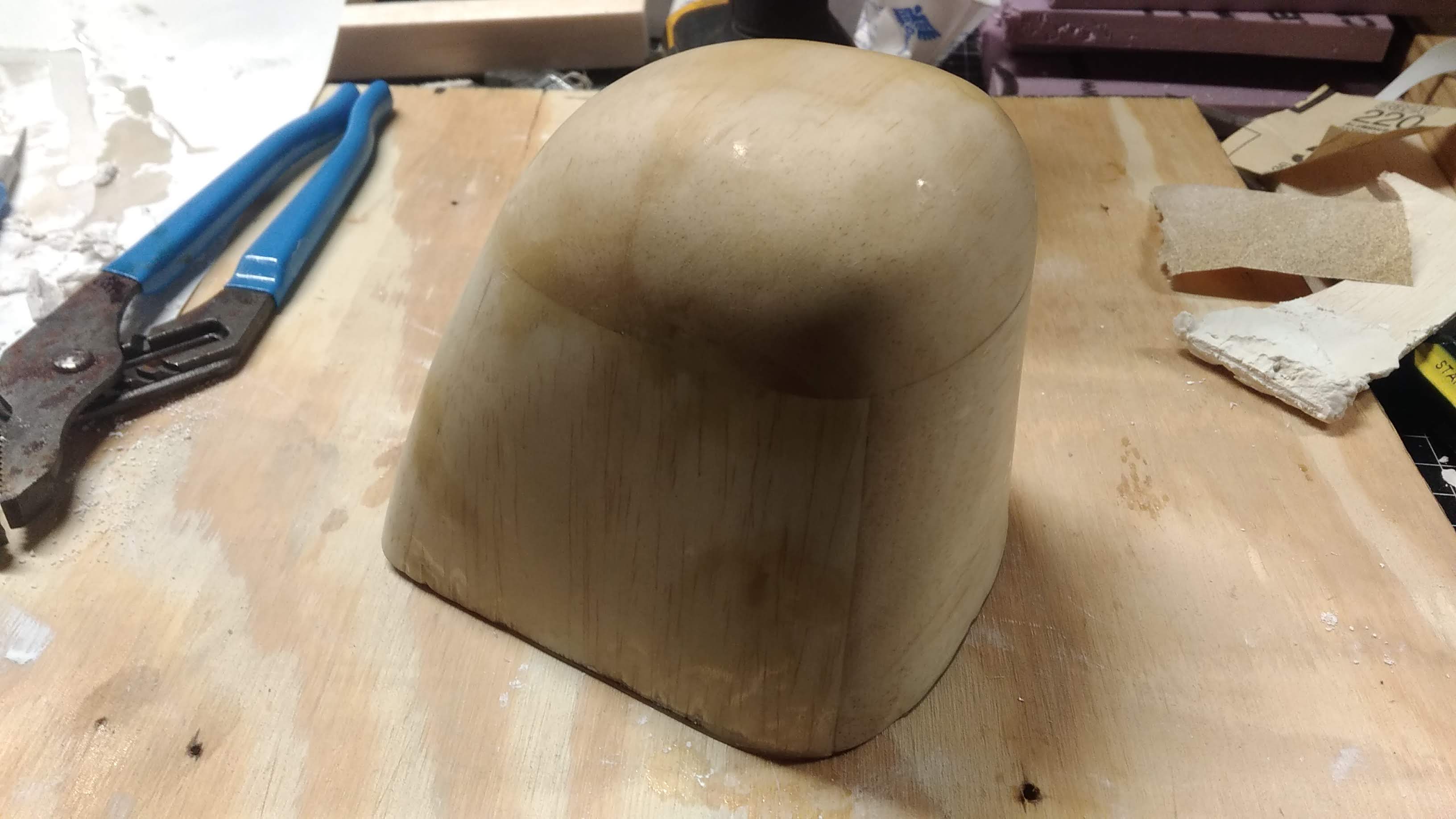
View attachment 178602

I wanted to kind of paint it in plaster to make the female mold but I quickly determined it didn't dry fast enough and would all just drip off. So, I made this little container to put the plaster in and then put the plug in the plaster.
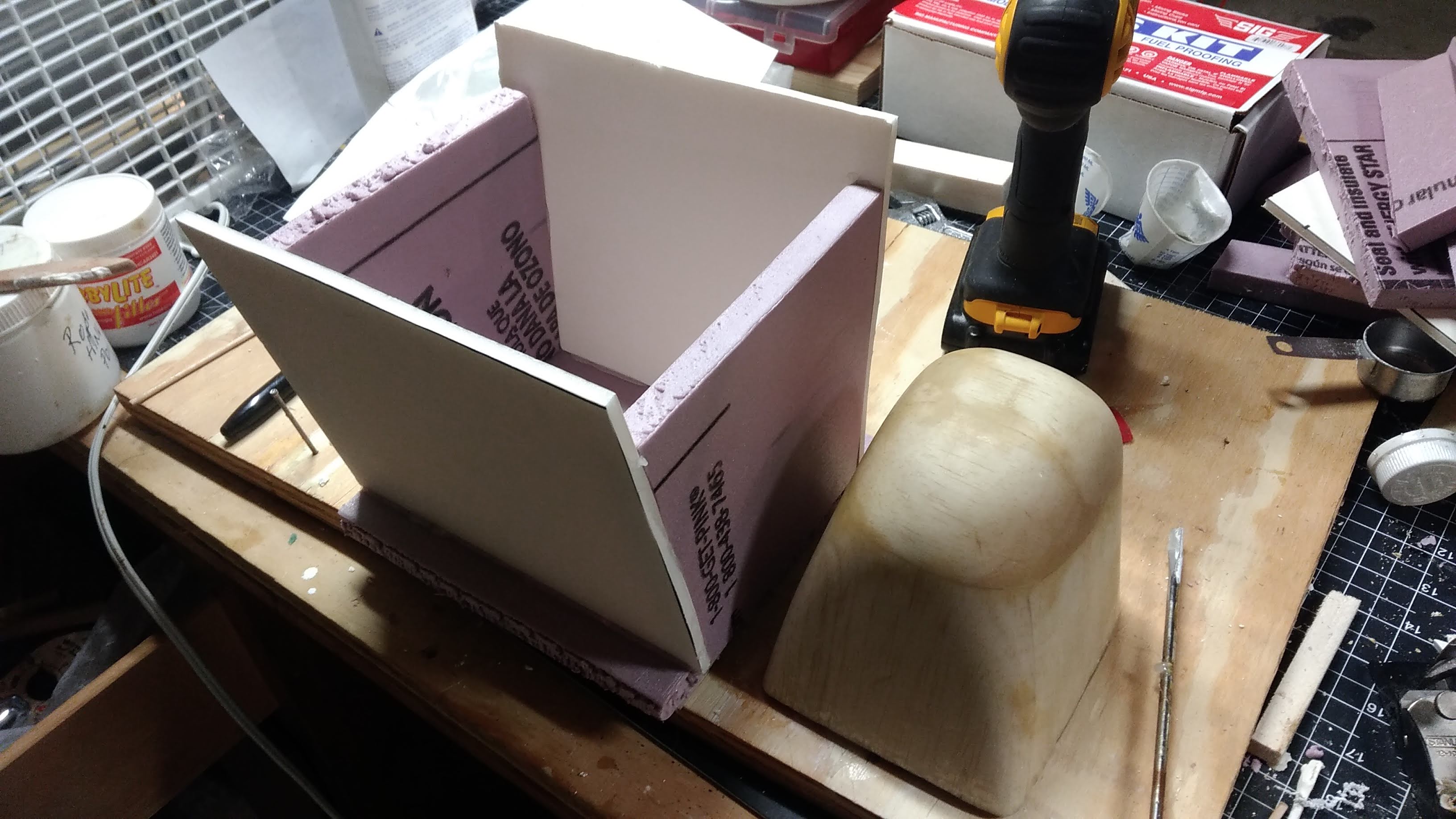
View attachment 178603

Unfortunately I did not have enough plaster to put the whole plug all the way in. It came up about 1/2 an inch short, which theoretically should not be a problem as I cut the plug a little long anyway. However if it is a problem I can reuse the plug as a negative mold instead - that way I would put the glass cloth directly on the plug using release wax to prevent it from just sticking to the plug permanently. Now to wait for the plaster to dry out...
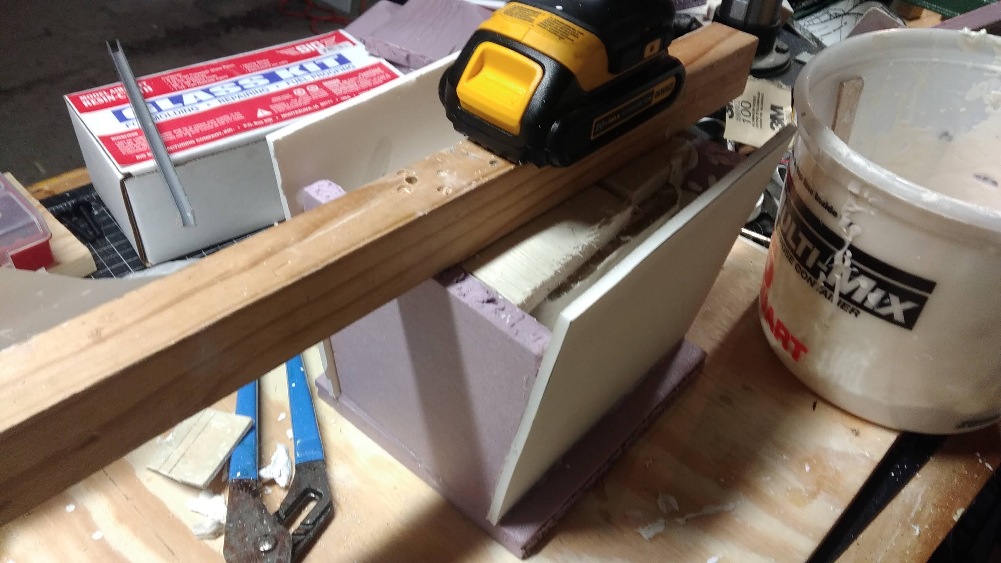
View attachment 178604
I've been thinking of doing something similar for a while, using scrap construction timber for plugs and cornice cement for the mold. What sort of release agent do you use on the plaster when making the fibreglass part?
 

speedbirdted

Legendary member
I've been thinking of doing something similar for a while, using scrap construction timber for plugs and cornice cement for the mold. What sort of release agent do you use on the plaster when making the fibreglass part?

If anythings for sure don't do the method that I described in the quoted post :p it ended up being a waste of time. Vacuum bagging is really the way to go as it gives you very smooth parts needing minimal extra work to finish as well as giving you very good adhesion between layers.

I make all my molds out of Ultracal. I'm not sure if you can get it in Australia without incurring some ridiculous shipping fees but if you want to try using cornice cement I would test it on a small scale for minimal material waste. Building type cements tend to be a poor choice as they're usually meant to plug gaps and not adhere to fine details of a given surface as mold making materials are, and they also tend to be more porous, which will affect the quality of the finished part significantly. You can also use plaster of Paris which takes up detail better but the molds tend to be very fragile and generally don't survive making more than one or two sets of parts.

I used to use dedicated release compound supplied by Sig for molds but upon running out of that and discovering that another tiny container of it cost like $10, I tried carnauba wax (the stuff you polish car bodies with) and it works just as well and can be bought locally pretty much anywhere.