speedbirdted
Legendary member
So, this is a bit unusual as I'm posting about this airplane after it's not only been built but had a successful few flights. A bit of background though for the uninitiated: I built this plane from a long-discontinued Great Planes kit I got for cheap, from October 2019 to about January of this year. Slow progress I know but I had personal issues to tend to at the time. I decided it was best to wait for good weather until I maidened it, which I finally got around to doing on June 28.
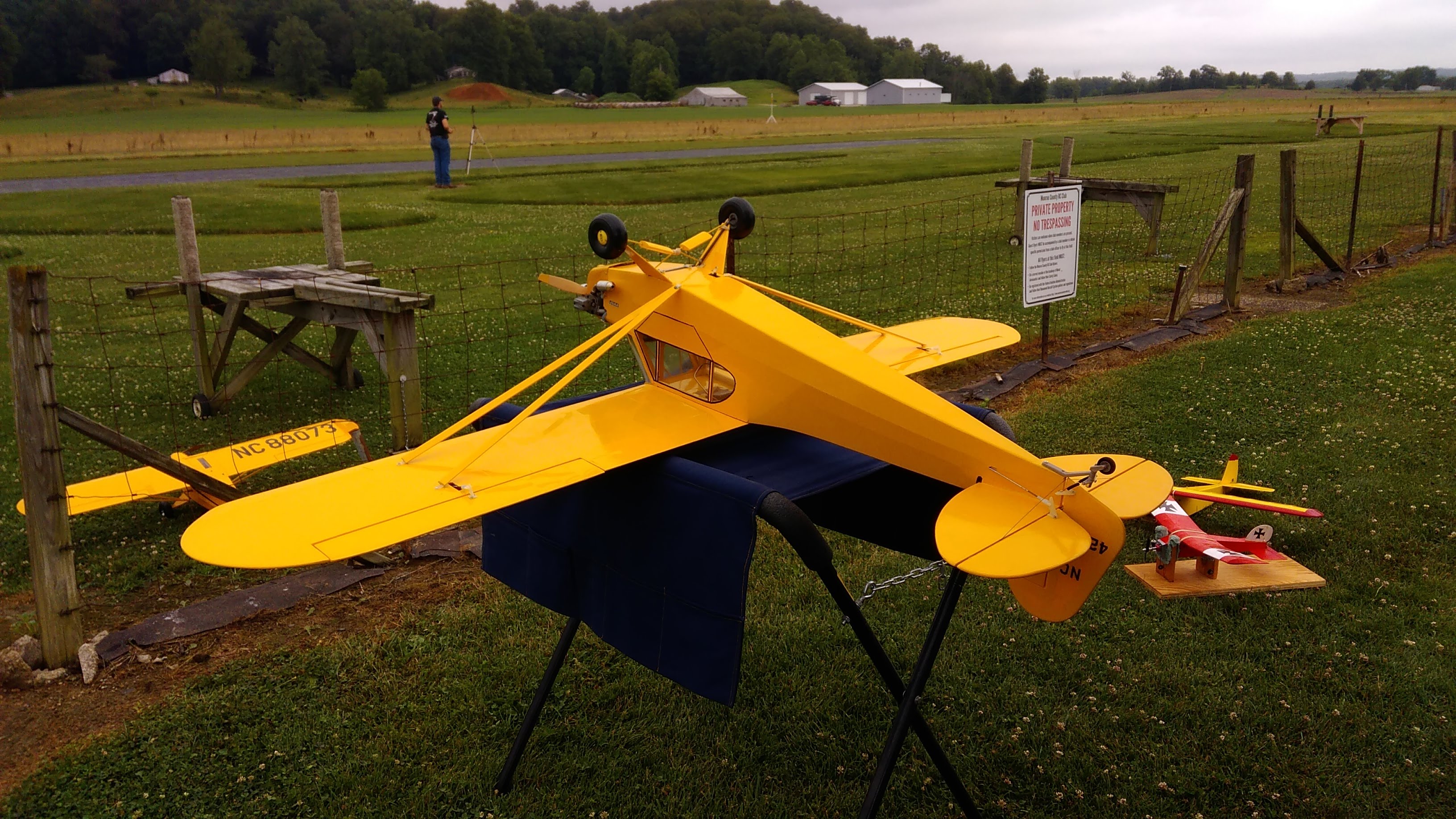
After that I had to do some changes because there were... issues. Most severely, the ailerons. This has on the plans the old style of driving both ailerons from one centrally mounted servo using bellcranks; nowadays there's no real need to do this as servos come pretty cheap. The wing struts also fluttered severely and one of them actually failed in flight, but luckily it just fell away harmlessly and they serve no structural purpose so it's not like there was any problem with it not being there. I found it later in the bean field and some damage to the nylon strap that holds it on was the only harm. This is entirely caused by there not being any jury struts, which is stupid from both a structural and a visual standpoint. A cub just looks wrong without them honestly. Other less severe problems included a crappy CG requiring a bit more than the 1 ounce of nose weight I'd already stuck on and the sad excuse for tail rigging I set up fluttering horribly. Use cables, not music wire kids! The landing gear suspension also popped out of place. I'll bind and solder that, since zip ties clearly don't work...
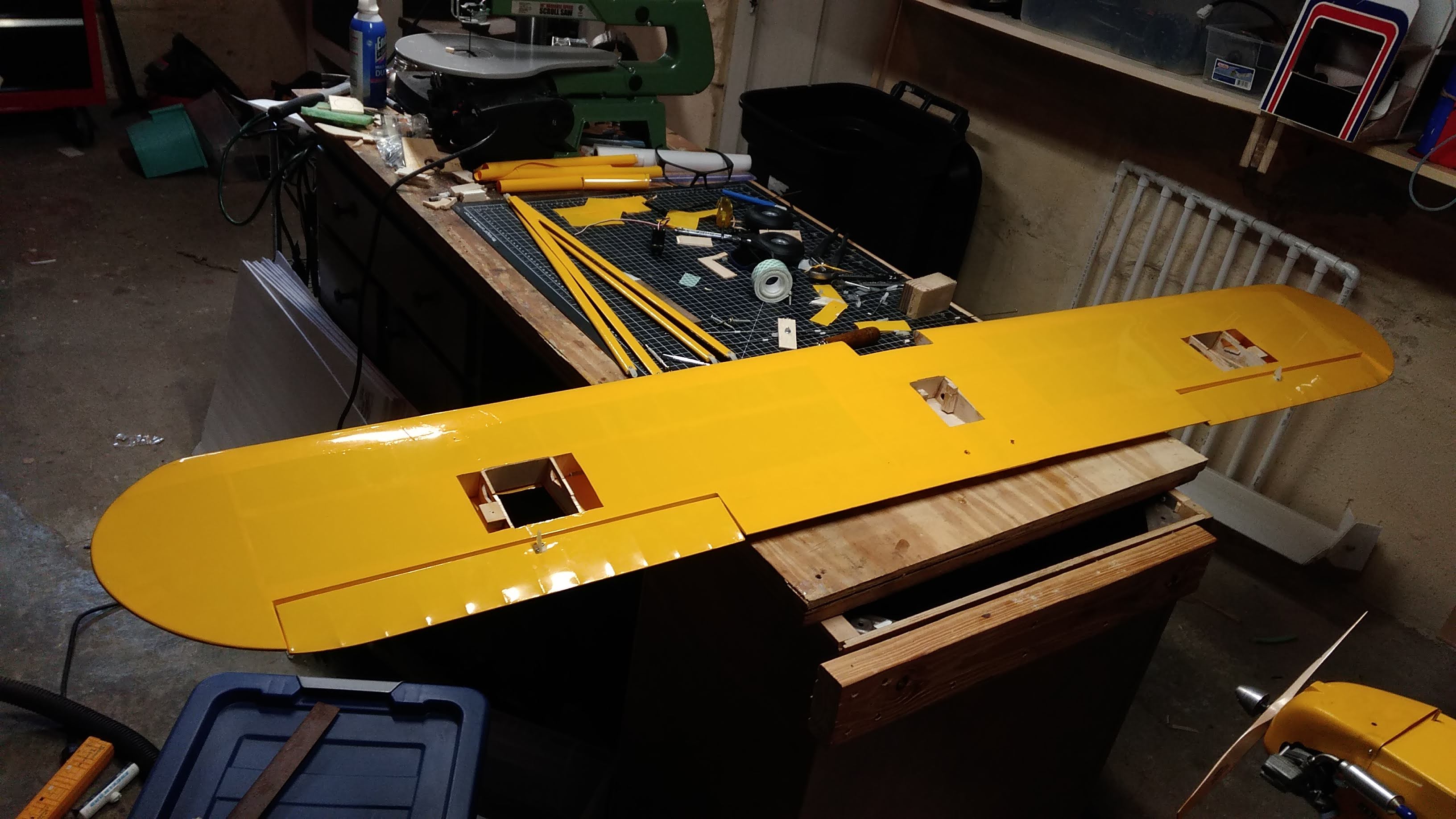
So the day after I tore the wing apart to replace the cruddy servo system. Here's a picture of when I had prepped the wing for installation of the servo door mounting blocks. The way I did the servo mounting is they actually get mounted to the doors, that way they can be easily removed for repair or replacement.
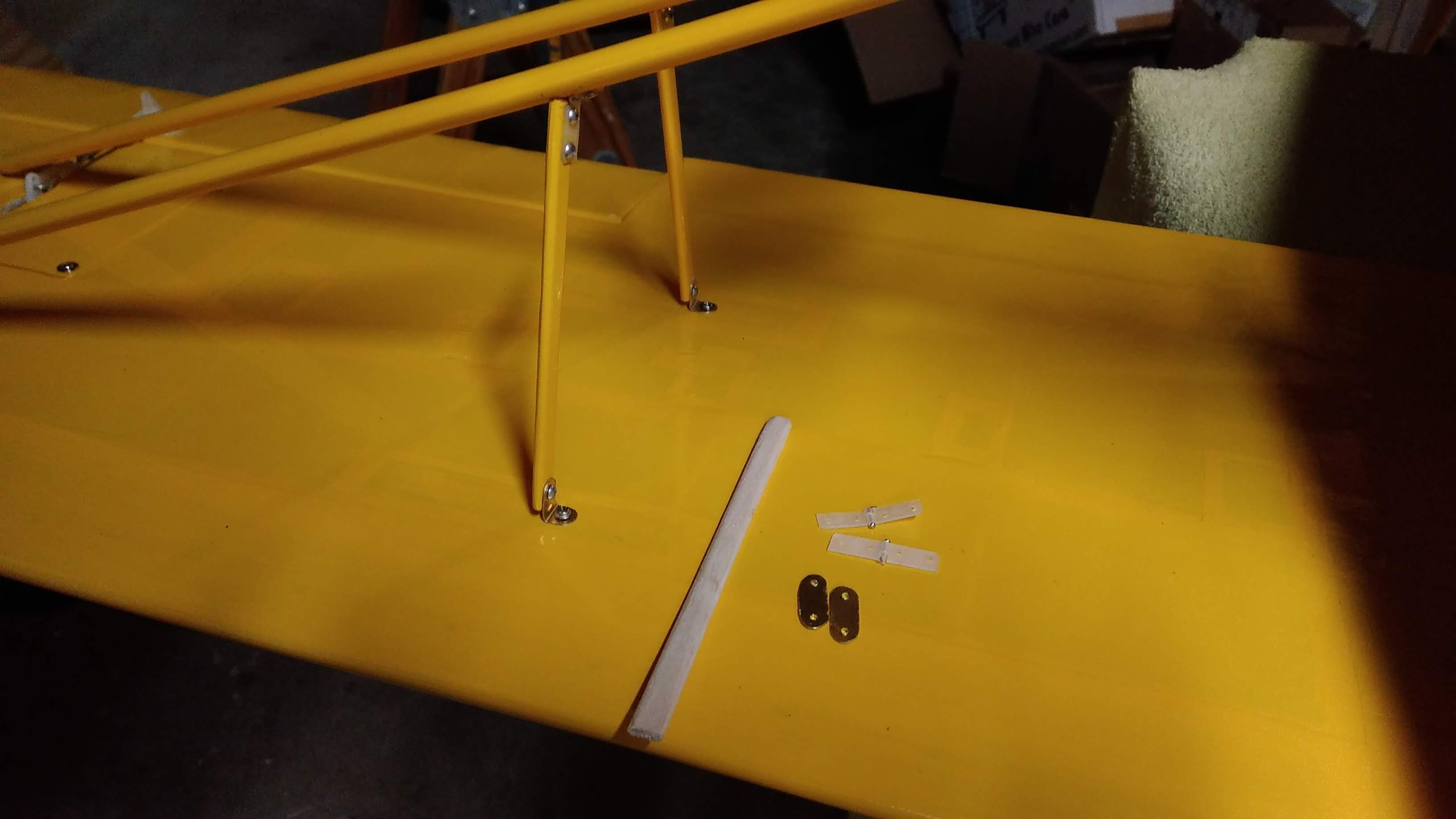
Next came the jury struts. These are made from 1/8 inch thick basswood cut down to size, and they are secured with handmade brass L-clamps to the wing, and a cut-down Dubro pinned hinge on each side to the struts. This way the jury struts, and the strut assembly as a whole, can be folded flat against the wing and it will fit in a wing bag. I had to cut up the wing covering more to add the plywood mountings for the jury struts and add another patch over it. Here is a completed strut, next to the parts used to build one.
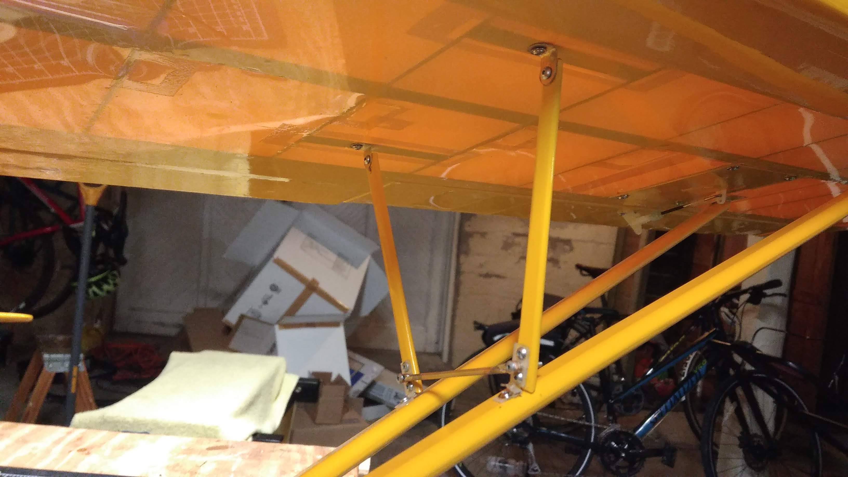
Now, for the component of the strut that runs across between the two struts, I did something a bit different. I considered just making another basswood cross member but instead I decided that it would look more realistic to use a brass tube. The problem with that is how to mount it. I considered at first flattening the tube on one side and then drilling through it into the strut, effectively using the plastic hinge material to make a locknut, but that would have been too weak. The problem was solved instead by again flattening the tube, but then wrapping the flattened section tightly around the tube and filling the hole with solder. I then drilled a hole slightly smaller in diameter than the screw through the solder. Solder is soft enough for the screw itself to act as its own tap, and the result is the mount is very resistant to coming off and is also very stiff. This was the result (yeah, this picture kind of sucks, but I spend too much money on planes to afford a good camera)
After I did all these modifications the plane was ready to fly again. I took it out earlier today. And it flew much, much better! Sadly though my dad's abilities with a camera are... questionable, and this was pretty much the best picture we got of it flying


After this flight though I still had a couple of things to fix, though they were pretty minor still. I went and loctite'd some screws that got unhappy from the engine vibration, and that was pretty much it. So, if the plane flies successfully as it is, and the build is complete, why make a thread?
Well, the build is not complete. A flyable plane doesn't mean I'm done with it, it just proves the concept. Now I wanna make it cooler
I've got some things I want to do, and some things I know I'll need to do in the near future, and I'll log them here. So here's a list for now.
We start at the front.
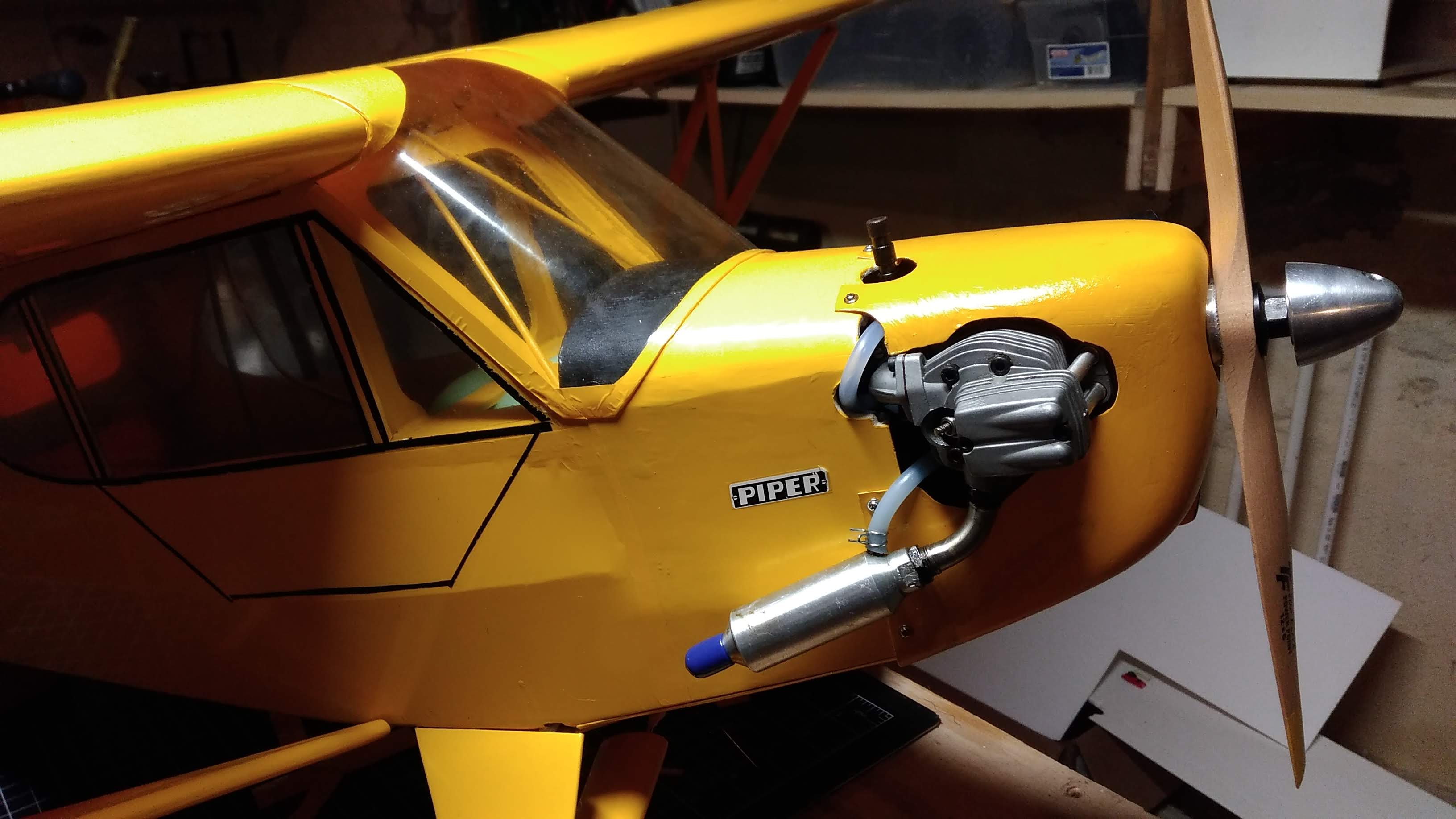
Oh boy, ain't that a circus and a half! So first and foremost, the cowling. It's the standard ABS cowling that came in the kit. I did not have much in the way of high hopes for it initially, and my sentiment remains unchanged now that it has some use on it (and by that I mean barely four flights...) I don't like it for a multitude of reasons. First and foremost, ABS is pathetically weak. When I removed the cowling yesterday to add extra ballast, I noticed the cowling had some visible fatigue around the bottom edges where it meets the fuselage underside and around literally every single screw hole (even though I was careful to avoid overtightening it!) Well, after today's flights, there appeared cracks a solid 1" long in the bottom corners of the cowling, and cracks extending to the edges from the screw holes. Dammit. This is why we don't make things out of ABS!!
So, needless to say, a new cowling is in order. Problem is - this kit was probably discontinued before I was even born. Spare parts are not an option here. Not like I would want the stock cowling anyway, as much of a chunk of garbage as it is. So, it's time for fiberglass. I have two ideas here - either, somehow, directly use the old cowling as a plug to form a new one, or make a plug out of foam using the cowling and firewall dimentions and coat it with release wax, and use that instead. Option two is better I think, because I want this cowl to have some extra features over the stock one, as well as being a slightly different shape - the (I think) pre-1940 Cub cowling has a more rounded underside and honestly I like it more. It'd also have the ability to separate into two pieces like fullscale Cubs do. This would be advantageous as it would prevent having to cut unnecessary holes in the cowling to get to things like the low speed adjustment.
Speaking of the engine, I have some plans for it too. The engine I selected, an ASP FS52AR, which is a clone of the relatively well-known OS 52 Surpass (and by clone, I mean clone. They have 100% parts cross-compatibity. Mine actually has a genuine OS piston and conrod installed

 ) actually has a perfectly adequate amount of juice for this plane, despite my worries. As much as I wanted to stick it on, I guess my Saito 56 will stay benched for now. However what I will be changing is the orientation of the engine. Initially, I thought the cylinder head poking out of the cowling side was pretty cool - overheating is certainly never a problem - but, now every time I have to fly the opposite leg of the pattern... I have to look at the stupid dummy engine on the other side. And boy is it disgusting. I tried to do as good a job making it sexy as possible but it's literally just two pieces of plastic CA'd together so there's not really a lot you can do with it. So, I think my only course of action here is to invert the engine. It should fit into the cowling fine, with the valve cover the only part protruding, and that's fine by me. Cooling I think will also be fine, given I open up the oil cooler hole at the bottom of the cowl to get some extra air in, and cut some extra holes in the bottom rear edge of the cowling to let cooling air escape. Remember, cooling air is useless if it has nowhere to go, and that's why you should cut your exit holes larger than your entrance ones. I might also make a custom exhaust system with either a smaller muffler or no muffler at all, so it can exit at a more scale location. In the case of no muffler, I'll have to put a pressure nipple onto the exhaust header.
Now with the engine out of the way this gives me both sides of the cowling to play with. I want to construct a much more scale, detailed dummy engine, identical on both sides. I remember seeing an engine kit for 1/4 scale cubs constructed out of stacked sheets of thin, laser cut balsa, and it honestly looked damned amazing. Problem is I was never able to find a 1/5 scale equivalent and the 1/4 kit would be much too large. So, I guess I'll have to design it myself. I have my own laser anyway and a decent amount of CAD knowledge, and cutting stuff with a laser is usually a strictly 2D activity so bumbleheads like me can do it just fine That or I can flash a few bucks at someone with a 3D printer and have them make me something instead, though I'm not sure how 3D printed parts would tolerate an engine spitting hot oil everywhere.
A more minor bit is the windshield. It actually looks okay in the above picture, but I assure you, it is far from that. Unfortunately when I got the kit, it had been sitting in a strange position in the box for so many years that it was severely warped and folded out of shape. Some careful heating and forceful bending got it to where it is in the picture, which is semi-presentable but still pretty crappy looking. Surprisingly - a Cub windshield actually contains no compound curves, and so making one from a sheet of thin plastic will not be terribly hard. I'm then going to hold it in place using screws, as that would look much nicer. This would also involve making some balsa blocks to secure against the interior edges of what was previously the outer edge of the windshield - see the places where there is covering film on the windshield? None of that will be plastic.
Now we get to the more drastic stuff...
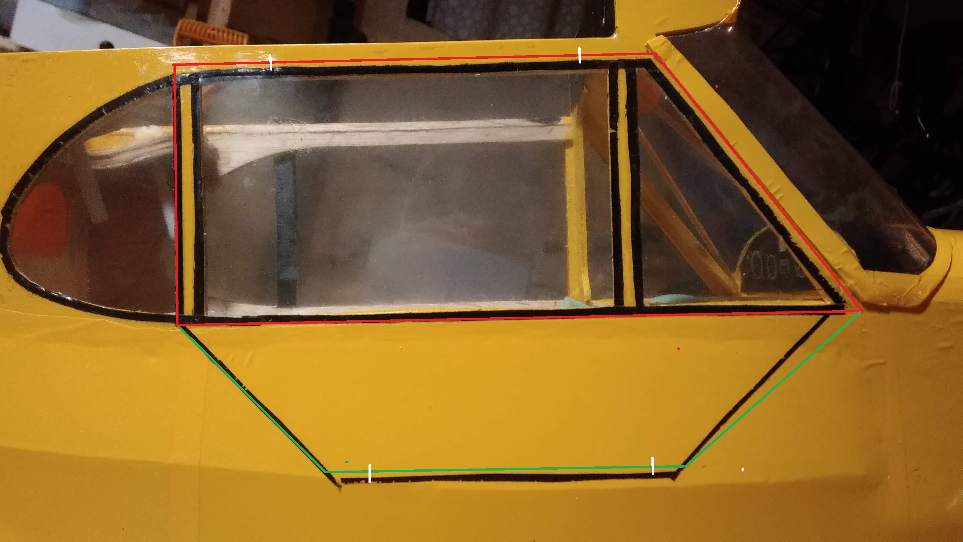
And, here's a feature I don't think enough cubs have. Functional door! And now please excuse me as I use this outstandingly poor MSPaint drawing to explain what I'm about to do. This is a pretty standard door setup for a Cub, but it will be complicated by goings on inside the fuselage which I'll explain in a bit. The red outline is the window, and the green is the door. The white lines are the intended hinge placement, which allows the window to hinge upwards against the wing and the door to hinge downwards against the fuselage. You may notice that the door outline is not aligned with the door decal currently there and this is completely intentional - it has to do with the location of the servo tray, and I'll elaborate on that in a bit. I think I'll use line hinges angled at 90 degrees, 45 in each surface, so that the hinge line is outside the fuselage and allows the door to fully open and rest against the fuselage flatly when opened. I'm not sure how I'll keep the windows and doors open in flight (because it's illegal to fly a Cub with the doors closed ) maybe I'll use some neodymium magnets hidden in the fuselage and wing.
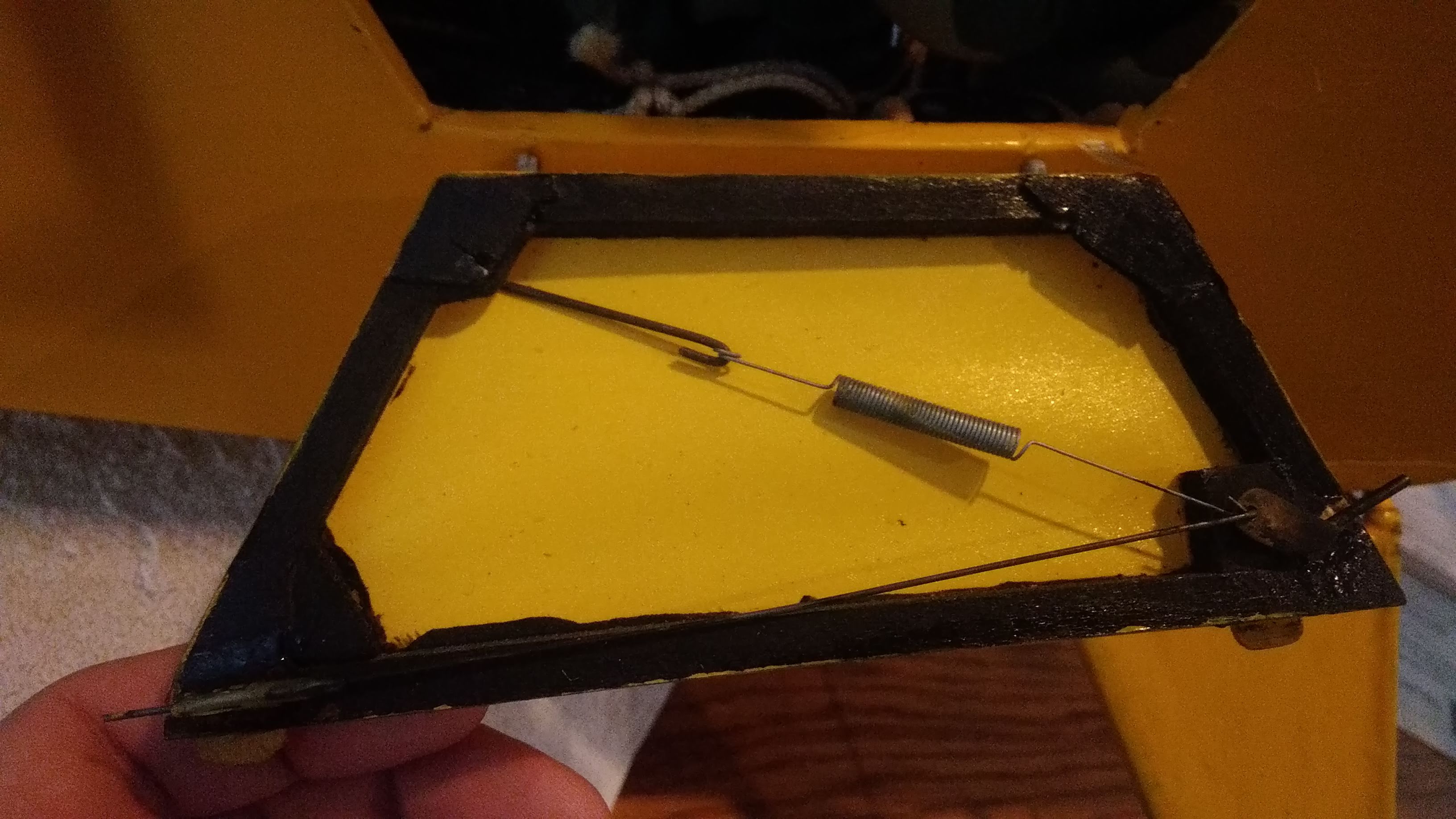
Here's how I intend to do the door latching when closed. The bottom of the door will be notched in such a way that it holds the window closed as well. I honestly don't remember who's airplane this was on - but if you happen to know the guy that owns it, don't tell him I'm stealing it As you can see the latch running through the brass tube on the left is actuated by the handle, which is held closed by the spring. Pretty easy to make...
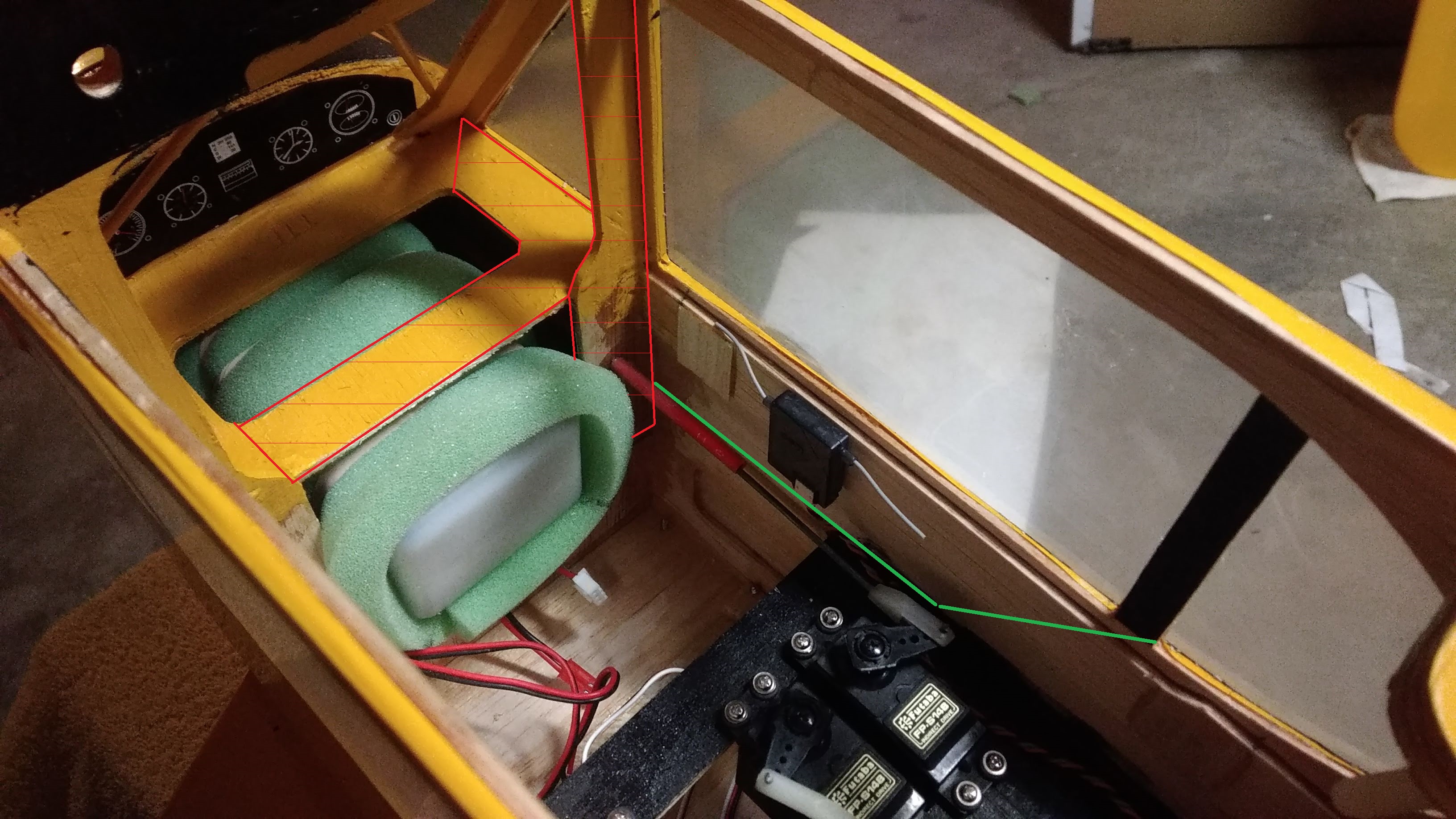
And now here is where things get ugly. Yeah, the inside of this airplane was clearly not designed with the intent of adding a door. All the parts outlined in red with slashes through them will be removed entirely. The green is about where I think the door outline will go - yeah, it looks kind of weird because of perspective. Notice the depth of the door is limited by the servo tray - I could make something lower profile, but that's tons of work, and that servo tray is incredibly hard to get to. Having a big gaping hole in the side of the plane will also let me finish off the interior paint job some more.
The removal of those side pieces will cause some things. Namely, I have to move the throttle servo. No biggie, I think what I'm gonna do is replace the standard size one with a 9 gram and move it forward, next to the fuel tank. Speaking of the fuel tank - the only reason it sits as far back as it does here is because the hoses didn't line up with the holes in the firewall perfectly, so this is the farthest forward it can go without causing kinking. Previously I couldn't solve this problem by drilling correctly placed holes because the engine was in the way, but I'm going to yank it off. I think I'm gonna just drill a big hole in the firewall the diameter of the bung, structure allowing, which will allow the tank to move forward nearly 2 inches, pretty much getting it out of the way of the door entirely.
My current concern with this is cutting out that much material might sacrifice a bit of strength. But, this plane will never do precision aerobatics so I don't think it'll ever see enough G-load for that to really be an issue...
I already know that all this will take forever to do. Be patient! I think I'll start with the cowling...

After that I had to do some changes because there were... issues. Most severely, the ailerons. This has on the plans the old style of driving both ailerons from one centrally mounted servo using bellcranks; nowadays there's no real need to do this as servos come pretty cheap. The wing struts also fluttered severely and one of them actually failed in flight, but luckily it just fell away harmlessly and they serve no structural purpose so it's not like there was any problem with it not being there. I found it later in the bean field and some damage to the nylon strap that holds it on was the only harm. This is entirely caused by there not being any jury struts, which is stupid from both a structural and a visual standpoint. A cub just looks wrong without them honestly. Other less severe problems included a crappy CG requiring a bit more than the 1 ounce of nose weight I'd already stuck on and the sad excuse for tail rigging I set up fluttering horribly. Use cables, not music wire kids! The landing gear suspension also popped out of place. I'll bind and solder that, since zip ties clearly don't work...
So the day after I tore the wing apart to replace the cruddy servo system. Here's a picture of when I had prepped the wing for installation of the servo door mounting blocks. The way I did the servo mounting is they actually get mounted to the doors, that way they can be easily removed for repair or replacement.

Next came the jury struts. These are made from 1/8 inch thick basswood cut down to size, and they are secured with handmade brass L-clamps to the wing, and a cut-down Dubro pinned hinge on each side to the struts. This way the jury struts, and the strut assembly as a whole, can be folded flat against the wing and it will fit in a wing bag. I had to cut up the wing covering more to add the plywood mountings for the jury struts and add another patch over it. Here is a completed strut, next to the parts used to build one.

Now, for the component of the strut that runs across between the two struts, I did something a bit different. I considered just making another basswood cross member but instead I decided that it would look more realistic to use a brass tube. The problem with that is how to mount it. I considered at first flattening the tube on one side and then drilling through it into the strut, effectively using the plastic hinge material to make a locknut, but that would have been too weak. The problem was solved instead by again flattening the tube, but then wrapping the flattened section tightly around the tube and filling the hole with solder. I then drilled a hole slightly smaller in diameter than the screw through the solder. Solder is soft enough for the screw itself to act as its own tap, and the result is the mount is very resistant to coming off and is also very stiff. This was the result (yeah, this picture kind of sucks, but I spend too much money on planes to afford a good camera)

After I did all these modifications the plane was ready to fly again. I took it out earlier today. And it flew much, much better! Sadly though my dad's abilities with a camera are... questionable, and this was pretty much the best picture we got of it flying

After this flight though I still had a couple of things to fix, though they were pretty minor still. I went and loctite'd some screws that got unhappy from the engine vibration, and that was pretty much it. So, if the plane flies successfully as it is, and the build is complete, why make a thread?
Well, the build is not complete. A flyable plane doesn't mean I'm done with it, it just proves the concept. Now I wanna make it cooler
I've got some things I want to do, and some things I know I'll need to do in the near future, and I'll log them here. So here's a list for now.
We start at the front.

Oh boy, ain't that a circus and a half! So first and foremost, the cowling. It's the standard ABS cowling that came in the kit. I did not have much in the way of high hopes for it initially, and my sentiment remains unchanged now that it has some use on it (and by that I mean barely four flights...) I don't like it for a multitude of reasons. First and foremost, ABS is pathetically weak. When I removed the cowling yesterday to add extra ballast, I noticed the cowling had some visible fatigue around the bottom edges where it meets the fuselage underside and around literally every single screw hole (even though I was careful to avoid overtightening it!) Well, after today's flights, there appeared cracks a solid 1" long in the bottom corners of the cowling, and cracks extending to the edges from the screw holes. Dammit. This is why we don't make things out of ABS!!
So, needless to say, a new cowling is in order. Problem is - this kit was probably discontinued before I was even born. Spare parts are not an option here. Not like I would want the stock cowling anyway, as much of a chunk of garbage as it is. So, it's time for fiberglass. I have two ideas here - either, somehow, directly use the old cowling as a plug to form a new one, or make a plug out of foam using the cowling and firewall dimentions and coat it with release wax, and use that instead. Option two is better I think, because I want this cowl to have some extra features over the stock one, as well as being a slightly different shape - the (I think) pre-1940 Cub cowling has a more rounded underside and honestly I like it more. It'd also have the ability to separate into two pieces like fullscale Cubs do. This would be advantageous as it would prevent having to cut unnecessary holes in the cowling to get to things like the low speed adjustment.
Speaking of the engine, I have some plans for it too. The engine I selected, an ASP FS52AR, which is a clone of the relatively well-known OS 52 Surpass (and by clone, I mean clone. They have 100% parts cross-compatibity. Mine actually has a genuine OS piston and conrod installed
Now with the engine out of the way this gives me both sides of the cowling to play with. I want to construct a much more scale, detailed dummy engine, identical on both sides. I remember seeing an engine kit for 1/4 scale cubs constructed out of stacked sheets of thin, laser cut balsa, and it honestly looked damned amazing. Problem is I was never able to find a 1/5 scale equivalent and the 1/4 kit would be much too large. So, I guess I'll have to design it myself. I have my own laser anyway and a decent amount of CAD knowledge, and cutting stuff with a laser is usually a strictly 2D activity so bumbleheads like me can do it just fine
A more minor bit is the windshield. It actually looks okay in the above picture, but I assure you, it is far from that. Unfortunately when I got the kit, it had been sitting in a strange position in the box for so many years that it was severely warped and folded out of shape. Some careful heating and forceful bending got it to where it is in the picture, which is semi-presentable but still pretty crappy looking. Surprisingly - a Cub windshield actually contains no compound curves, and so making one from a sheet of thin plastic will not be terribly hard. I'm then going to hold it in place using screws, as that would look much nicer. This would also involve making some balsa blocks to secure against the interior edges of what was previously the outer edge of the windshield - see the places where there is covering film on the windshield? None of that will be plastic.
Now we get to the more drastic stuff...

And, here's a feature I don't think enough cubs have. Functional door! And now please excuse me as I use this outstandingly poor MSPaint drawing to explain what I'm about to do. This is a pretty standard door setup for a Cub, but it will be complicated by goings on inside the fuselage which I'll explain in a bit. The red outline is the window, and the green is the door. The white lines are the intended hinge placement, which allows the window to hinge upwards against the wing and the door to hinge downwards against the fuselage. You may notice that the door outline is not aligned with the door decal currently there and this is completely intentional - it has to do with the location of the servo tray, and I'll elaborate on that in a bit. I think I'll use line hinges angled at 90 degrees, 45 in each surface, so that the hinge line is outside the fuselage and allows the door to fully open and rest against the fuselage flatly when opened. I'm not sure how I'll keep the windows and doors open in flight (because it's illegal to fly a Cub with the doors closed
Here's how I intend to do the door latching when closed. The bottom of the door will be notched in such a way that it holds the window closed as well. I honestly don't remember who's airplane this was on - but if you happen to know the guy that owns it, don't tell him I'm stealing it

And now here is where things get ugly. Yeah, the inside of this airplane was clearly not designed with the intent of adding a door. All the parts outlined in red with slashes through them will be removed entirely. The green is about where I think the door outline will go - yeah, it looks kind of weird because of perspective. Notice the depth of the door is limited by the servo tray - I could make something lower profile, but that's tons of work, and that servo tray is incredibly hard to get to. Having a big gaping hole in the side of the plane will also let me finish off the interior paint job some more.
The removal of those side pieces will cause some things. Namely, I have to move the throttle servo. No biggie, I think what I'm gonna do is replace the standard size one with a 9 gram and move it forward, next to the fuel tank. Speaking of the fuel tank - the only reason it sits as far back as it does here is because the hoses didn't line up with the holes in the firewall perfectly, so this is the farthest forward it can go without causing kinking. Previously I couldn't solve this problem by drilling correctly placed holes because the engine was in the way, but I'm going to yank it off. I think I'm gonna just drill a big hole in the firewall the diameter of the bung, structure allowing, which will allow the tank to move forward nearly 2 inches, pretty much getting it out of the way of the door entirely.
My current concern with this is cutting out that much material might sacrifice a bit of strength. But, this plane will never do precision aerobatics so I don't think it'll ever see enough G-load for that to really be an issue...

I already know that all this will take forever to do. Be patient!
Last edited:


