It's been a while, but its time for a quick update:
I tested the cyclocopter and got 100g thrust at full throttle. The problem is that the motor weighs 80g, and the rest of the rotor weighs ~60g. I *think* that I can put hook up two rotors to one motor, so that's what I'm going to do when I actually try to build a cyclocopter. Along with the other changes that I've made, which should net me around 150g thrust per rotor and an 80-90g rotor weight, it should be able to hover. (Although it would have to be on a tether because the lightest battery I have is an 80g 3s 850mAh)
Along with only using one motor for two rotors, I'm also increasing the "wingspan" of the blades by a good 50%, which should be structurally manageable because I am also going to a symmetrical airfoil (should be much stronger). I don't have a picture from my slicer, but it's basically like this picture that
@quorneng posted earlier.
View attachment 204471
The problem with this is that I have to do 1 wall on the print for it (then 3 on the bottom to serve as the spar) to be light enough, but then there's sometimes rough/patchy spots because my 3D printer isn't good enough to put down a decent 1 wall print. I also tried printing it in 1 piece oriented with a 0 degree AoA on the bed, but that also didn't turn out so well. I also tried another way with airfoils, a spar, and a covering of plastic wrap, but that was kinda complicated and a bit heavy. I'm not quite sure what I'm going to try next, I might order some carbon fiber tubes for spars and 3d print airfoils to try to make a lightweight wing that way.
View attachment 204472
I also worked a lot with the struts and such that hold the airfoils in place, and I've gotten them lighter and more aerodynamic.
Here's the overall machine so far:
View attachment 204474
View attachment 204478
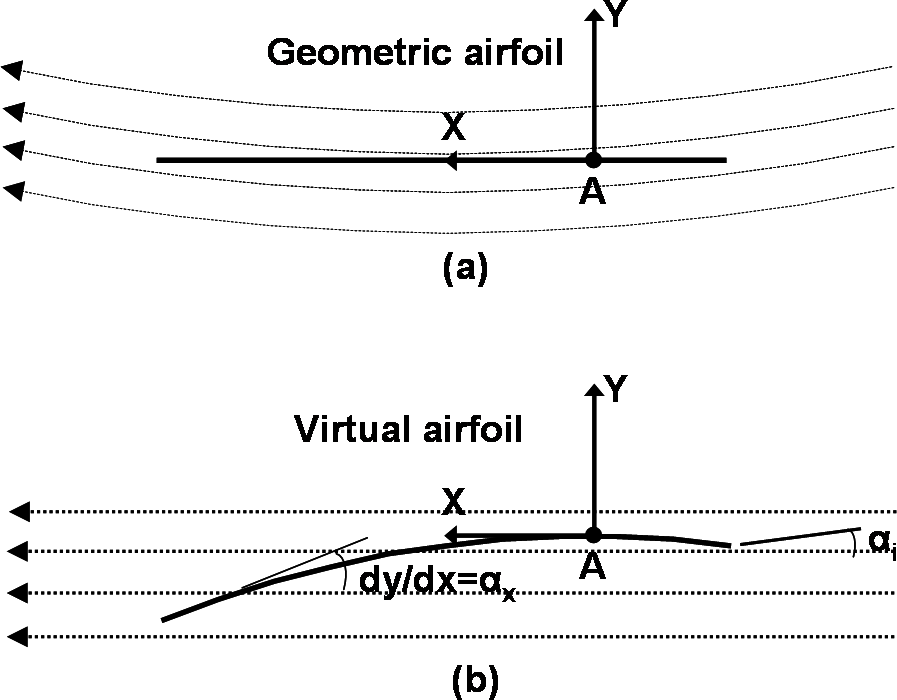
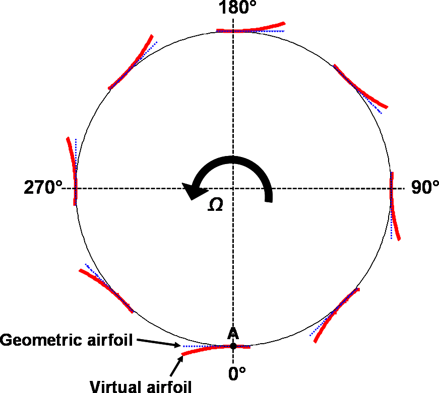
Oh, and here's the airfoil I've been going with. It's the NACA 0020, which was determined in a pretty long and interesting
research paper from Texas A&M to be the most efficient.
View attachment 204473