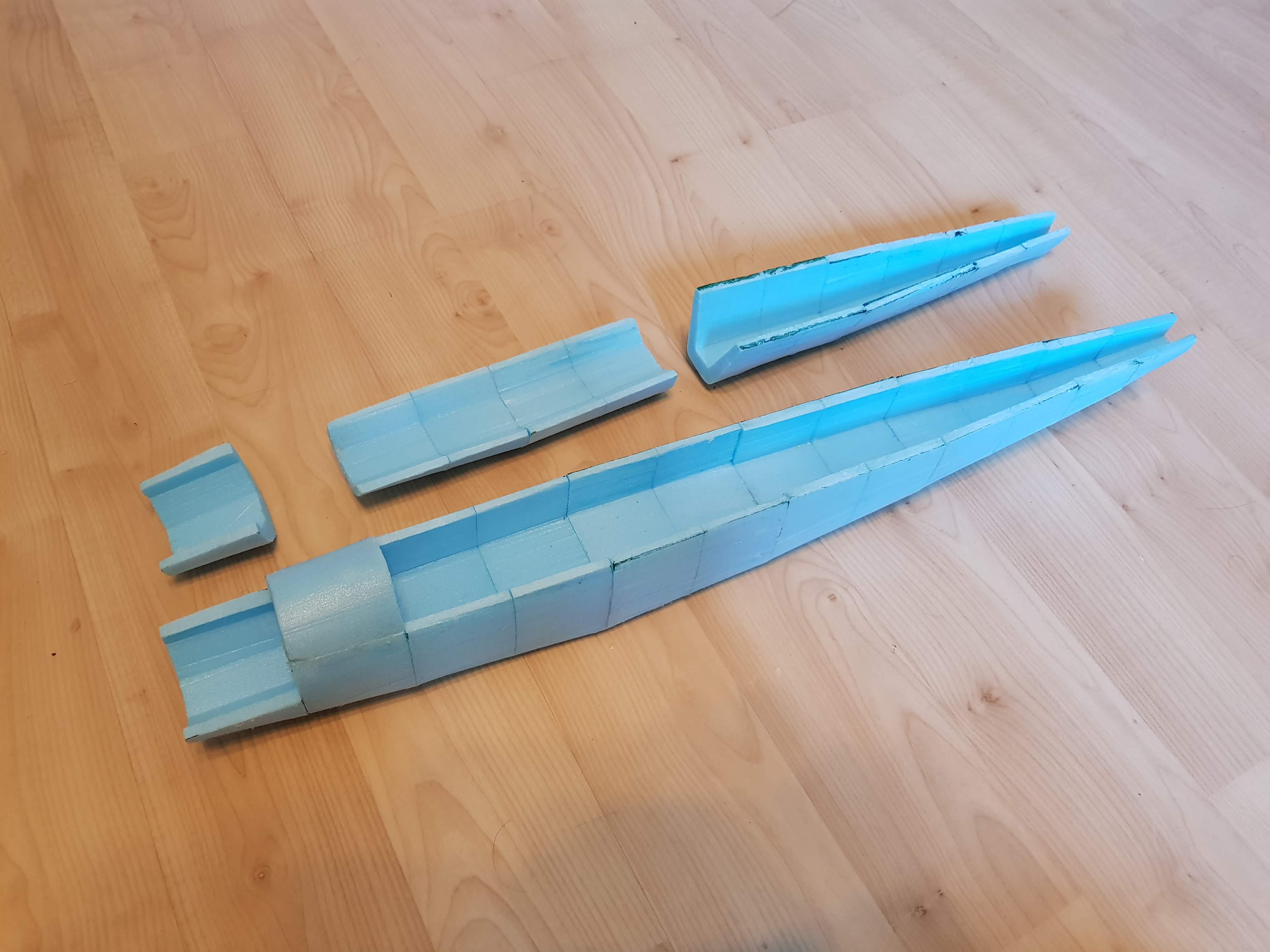
Man, life got busy quickly.... (Also a 1:10 BF 109 build.)

robobob

Member
So, it's been a hell of a long time since I've done anything RC/fliteTest related, and it's entirely because of the bane of existance well known to everyone between the ages of 16 and 25: Exams. The past couple of months have been absolute hell, but I'm pleased to say I've finally finished all of my exams, and am ready to reach for the skies. The other bit of good news that has arisen, is that I'm now officially taking a gap year. Some of the reasons for this decision are a little complicated, but the main one is because I want to pursue all of the crazy projects that I never really had time for while I was at school. Of course, included in these "projects" are all of my RC related endeavors. It was a little unfortunate that the moment I was actually getting somewhere with this wonderful hobby, my A level exams and coursework hit me like a freight train. The gap year, and other university related developments that have come into effect mean there is a high probability I will attend a flite fest in the next few years. If not next year, hopefully in three years time, as the university where I have chosen to study offers a one year study abroad scheme, with places available in three different american universities. This would be idea for me in terms of establishing connections, as living and working in America has long been a well cemented plan of mine and why not attend a flite fest along the way?

But what good would this post be in the Mad Builder's Corner, if I was only going to spend the entire time rambling on about my extremely boring life developments, that franctly matter not to the flite test community.
No, instead I also want to present a 1:10 Bf 109 Build. I've been working on this for a while, and before my entire life was overrun with education, I managed to complete the foam cut fuselage, as well as ordering some the electronics.
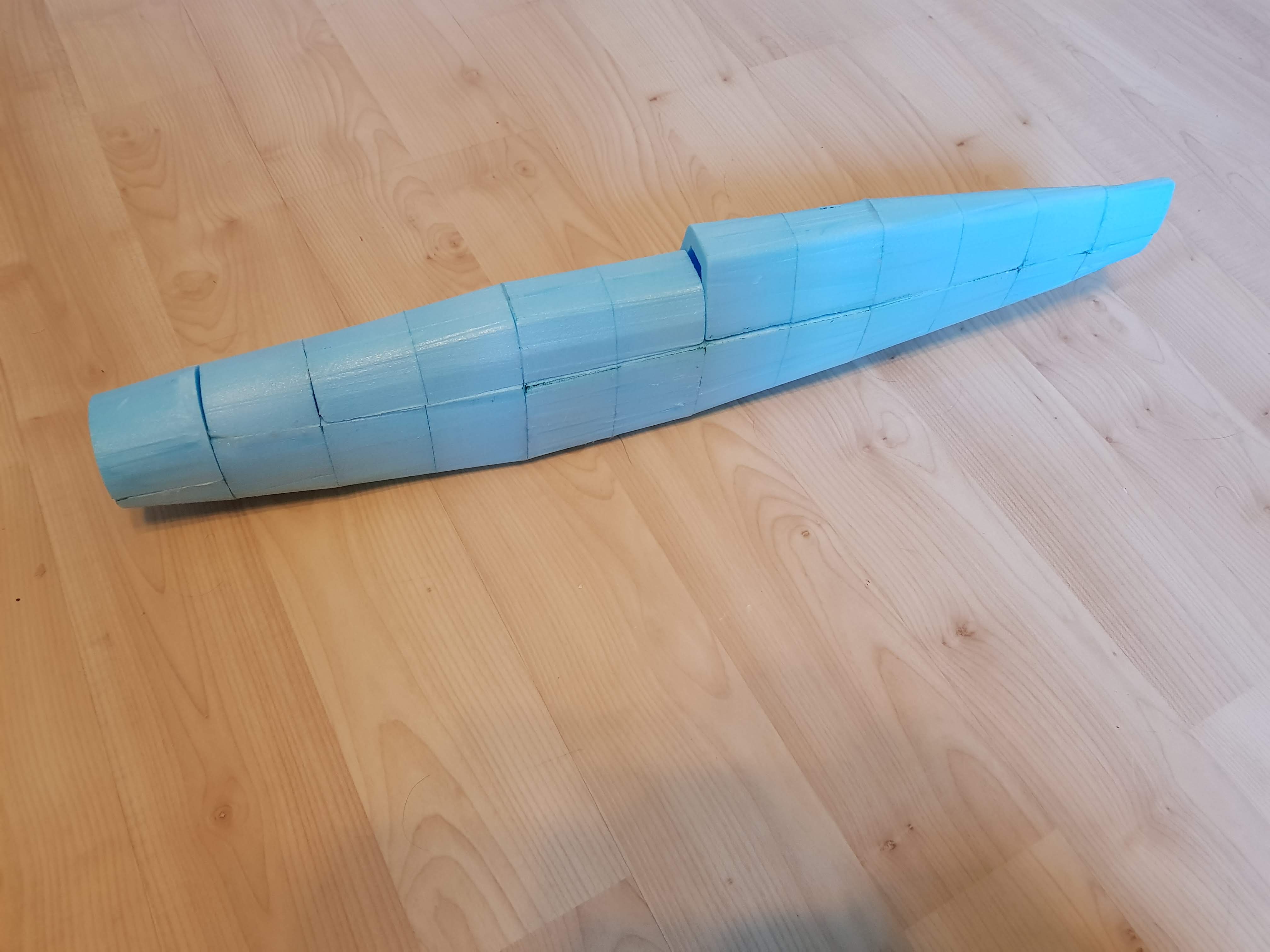
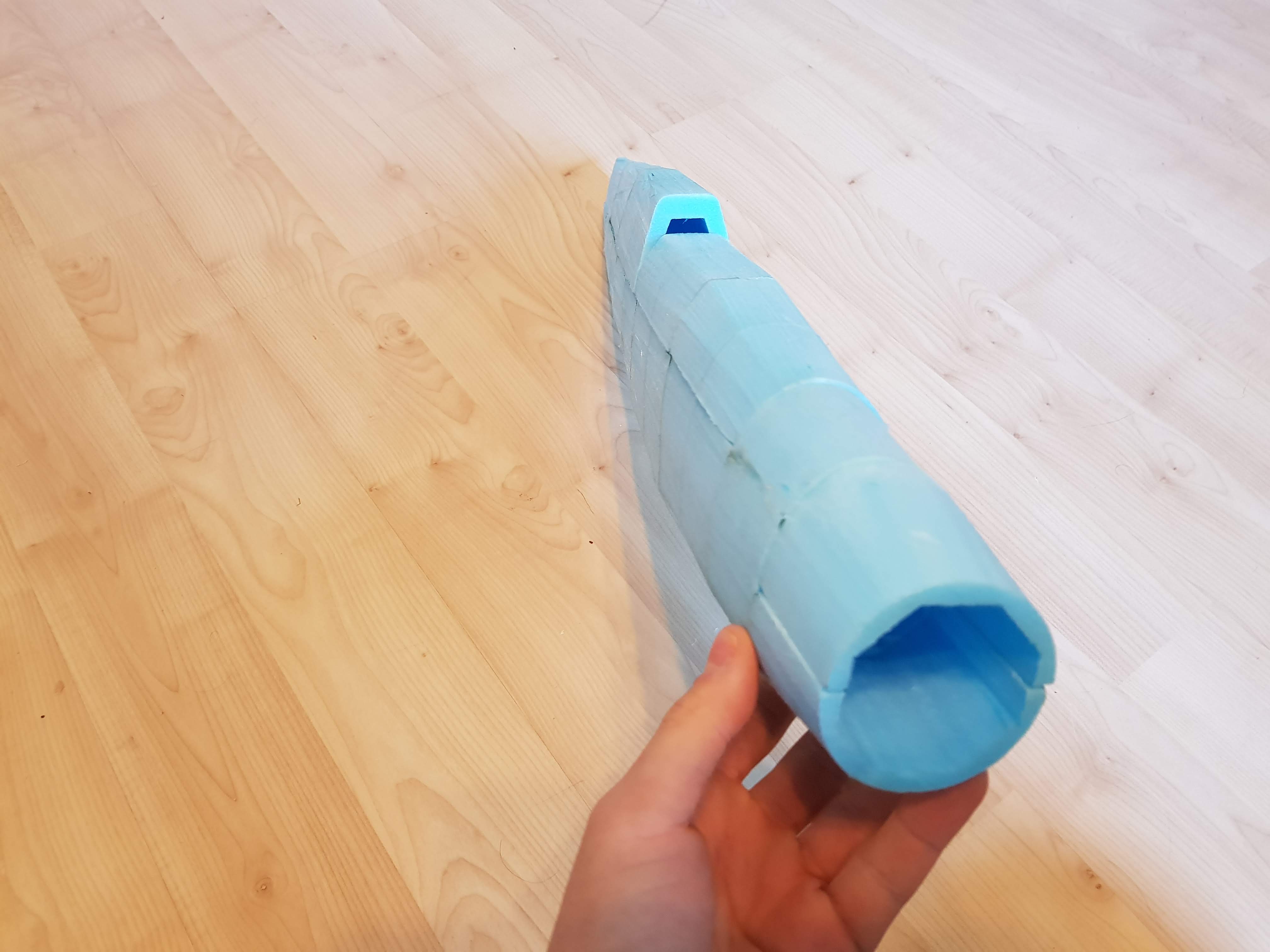
20180622_145623.jpg

20180622_145636.jpg
20180622_145656.jpg


On the list for the next week is hopefully getting the wing spars laser cut from 3mm plywood, and cutting the rest of the foam wing ribs, to hopefully have a finished framework before I leave to travel for three weeks.
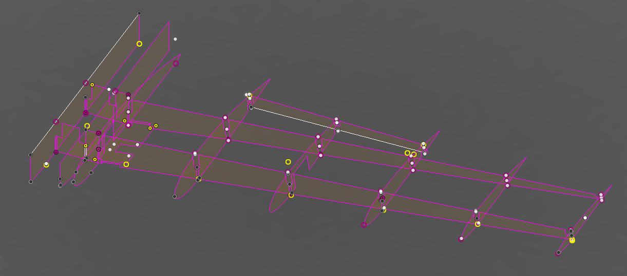
BF 109 wing 1.PNG


When I return I intend to cover this framework with a skin of 2mm depron, and additionally I should hopefully have access to my own 3D printer, allowing me to create 3d printed wing tips, tail section and cockpit.
The final stages of the build should comprise of applying a lightweight filler to the fuselage, to fill in all the ugly lips and gaps in the hot wire cut foam. Sanding it down to make it all nice, neat and symmetrical. Adding a single layer of ultra lightweight fiberglass for some added rigidity and to create a very smooth surface. And finally, weight allowing, painting the thing to make it look like the real deal.

I do hope that everyone has some good plans for summer, as well as the coming year.
 

Attachments

  • 1529677635864.png
    1529677635864.png
    167.3 KB · Views: 0

robobob

Member
So, I tried cutting out a few of the wing ribs by hand on some scrap foamboard, and the results were.... interesting. This might be my sheer inexperience at making foamboard aircraft, but I'm really struggling to create accurate, vertical cut lines through the foam board. While this may be fine for larger models and parts, these wing ribs are very intricate, and require perfectly vertical cuts so that they will fit onto the spars.
20180625_130137.jpg
20180625_130227.jpg
20180625_130408.jpg

My options now are more along the lines of:
  • Just say "what the hell" and bodge it together anyway.
    or
  • Laser cut the foam ribs as well, but be forced to re-draw the parts optimised for laser cutting. (A large pain in the nether regions)
    or
  • Build some wacky contraption, similar to the reciprocating needle cnc, except manually operated.
The last option has been something I considered for quite a while... In effect a miniature foam-dedicated fret saw, powered by an emax rs2205, a servo tester, and the cheapest 30A esc and lipo batteries available. This would of course, two main problems, the first being that it would require a whole load of 3D printing and fabrication to produce the damn thing, albeit, a rather useful tool it would be. And the second, that it would likely be extremely dangerous. While not really beyond a sewing machine or any workshop saw, I would rather not end up with a needle through my finger any time soon.

*Edit* It just suddenly hit me I could use a jeweller's saw blade, which goes down to a tiny 0.21mm in diameter. This would be even more precise, and theoretically allow me to make the machine much safer. There would not be any risk of a blade being driven downwards into my finger, only that my finger could collide with it laterally, which I would like to think is less dangerous, and easier to avoid.

All that said, the answer to the level of danger it would pose, would simply be, BE CAREFUL! It's effectively a reciprocating saw, don't treat it differently to anything else.
I would of course, love to learn if anyone else has faced this problem, and how they managed to overcome it.

I intend on heading to the local community workshop to use the laser cutters at 3:00pm this afternoon. I should hopefully at least have the first prototype spar done today. However, I discovered that they have a laser cutter large enough to do one huge spar across the whole wingspan. This would massively increase the strength of the whole design, and generally increase ease of construction, however, since they do not currently have the larger plywood sheets around, I would either have to get them to order it, or order it myself, either way delaying the build.
 
Last edited:

robobob

Member
Laser cutting success!

20180626_175628.gif


After two initial failures, one yesterday, the with the tolerances too tight, and one this morning with the tolerances too narrow, I managed to get a successful laser cut of all of the plywood wing parts this afternoon. The fit is a little loose, however slotting a scrap piece of foamboard into the gaps in the spars produced an extremely tight fit. My hope is that the foamboard wing ribs should create a good fit to hold everything square... *my cutting ability permitting*

20180626_132032.jpg
20180626_134052.jpg

As the space inside the wing is extremely limited, I need to achieve the slimmest profile for the gear retract possible. I decided to remove the mounting plate that came with the retract, and laser cut my own mounting plate, that could be integrated as a part of the wing, effectively removing an unnecessary thickness.


20180626_134443.jpg


My only worry is that the separate wing halves could be prone to split apart in any slightly acrobatic manoeuvres. I would love to cut the wing spars as two pieces rather than four, however this was not feasibly possible this week for two reasons.
  1. I would have needed to order a larger sheet of plywood to be able to fit both spars as one piece, which would not have arrived before I leave to go on holiday.
  2. The only laser cutter able to cut the wing spars at the size I needed, broke this morning.
With any luck after I return in three and a bit weeks' time, the large laser cutter will be working, and I will have time to order a large enough sheet of plywood, to cut the spars as one piece.

However, in a worst case scenario, and for some reason I end up deciding to use the two separste halves, I woukd like to think it will be okay.
The two halves of the wings will be glued to the underside of the plane, there will be a skin of 2mm depron covering the join on the underside, and on top of that, there will be a single layer of fibreglass reinforcement.

In addition to this I managed to start work on a decorative stand for the plane, because, why not?
20180626_195354.jpg


I intend on engraving some text and artwork onto this plaque on the side of the stand, giving a few details about the original BF 109 F4.
20180626_195412.jpg


As you might be able to see, the stand is currently missing a base. I stupidly designed the stand to attach to a base made from a scrap piece of 4mm thick plastic I had found lying in the scraps. When I tried to laser cut the base, it quickly arose that it was not made from acrylic, as the plastic was evidently not cutting correctly. I then found out that the plastic was infact polycarbonate, and there was no 4mm acrylic around. I decided to order some from amazon, and it is due to arrive on Thursday.

All in all, an extremely productive day, however I am still having doubts about cutting the foamboard ribs by hand. Also available in the same workshop is a flatbed CNC, which I could also potentially look into using to cut out the foam ribs. Plenty of options available, but I still fear that the final iterations will come after I return from holiday.
 

robobob

Member
Looking good, how big is this going to be?
It's a 1:10 scale, so approximately a 1m wingspan. There will be additional 3D printed wingtips, and an entire 3D printed tail section added on to what I currently have. The reason for the 3D printed tail section is so that I can fit all of the control rods and servos inside the body of the plane, using internal mechanisms to control the tail surfaces.

Additionally, I just finished up the artwork to be laser engraved onto the plaque on the side of the stand. It's simple, but should look really good on the clear acrylic, as it will lose its transparency where the laser cuts into the surface.
BF 109 F4 Art.png
 

robobob

Member
At last, something airworthy!

20180627_203635.jpg


So, this afternoon I decided I would give cutting the foam ribs one last try before I resorted to automation.
It occurred to me that my problems mentioned two posts back did not necessarily stem from an inability to cut straight. Yes this was a byproduct, but I realised the source of my problems was infact an inability to provide my undivided attention to cutting around the patterns.
Previously I was trying to hold the paper pattern to the surface of the foamboard, and use the other hand to cut around the outside, which meant I could only half concentrate on making sure my cuts were accurate.
My secret weapon to combat this came in the form of:

20180627_204647.jpg


Sewing pins.

Of course, I cannot claim the credit for this idea, as many members of this forum probably know. It should have occurred to me sooner, but I decided to consult the wisdom of the flite test community, and boy did it deliver. I found several threads from people asking how to fix flite test patterns to foamboard, and one regular recurring answer was to use pins.
I decided to give it a try, and it worked a treat!

20180627_203616.jpg
20180627_204402.jpg
20180627_204208.jpg


I have however, decided to deem this wing as a prototype, and wait till I return from holiday to manufacture the final version. Instead will use this half to test out things, such as covering the wing with depron, before moving to the final version. The new wing will use full length laser cut spars, that encompass what was two wing halves, as one piece. In addition to the greatly increased strength that this will provide, using some extra 3D printed parts, I can turn this into a detachable wing that screws in from the underside.
The perks provided by the single piece wing greatly outweigh the time and effort required to make it.

Tomorrow I will be going to engrave the plaque on the side of the stand, and if my acrylic arrives in time, also cut the base. This should at least mean, while there will not be any progress on the plane for some time, I will have a nice pretty stand to look at.
 

robobob

Member
Completed plane stand.

20180628_203409.jpg


So this morning I headed back to the local fablab armed with some extra 4mm thick acrylic, and adjusted laser cutting files with an additional thickness around the outside to accommodate for the kerf left by the laser. After cutting the first two parts, it was clear that the fit was absolutely perfect, and then I moved onto the remaining parts and the engraving. I'm really happy with how the stand came out.

20180628_203341.jpg
20180628_203045.jpg


Unfortunately, as mentioned previously there will not be any progress on the plane for the next three weeks...
However when I return home, the plan is to recut the plywood wing spars to create a, single, rather than split, wing construction, and push on with the rest of the build.

20180628_203951.jpg
 

robobob

Member
Testing testing testing... (pt 1.)

20180629_092531.jpg


This is just a quick update since I decided to test covering the wing this morning, and I feel I discovered a few important things for the future of this build. The depron covering is very rough and ready, but this is just a test, and the final version should be much neater.

20180629_092541.jpg


While the depron is nice and flexible, and formed a fantastic trailing edge, as you can see in the photo below, the leading edge left a lot to be desired.

20180629_092514.jpg


I ended up bending the depron to a curve by hand after it was glued down, which still looks messy and unpleasent, even though it's much improved compared to how it was just after I had glued it.

20180629_092800.jpg


But it is at least not all bad news. The electronics fit really well are not at all lacking space, and I was really quite happy with the general feel of the wing. The overall result was nice and light, and generally the depron conformed well to the aerofoil shape.
However it still lacks some torsional rigidity (Though the fiberglass might solve this), and after some closer inspection, the wing construction is not really square.
I'm also considering painting this wing just for a little fun...

Returning to the issues that I encountered, and things that I learned:
  • I need a glue with a much longer or much shorter working time, and thinner consistency. The glue I used this time was plain old stuff from a hot glue gun, however it's medium length working time and thick consistency left me with a situation where I needed about 5 pairs of hands to glue the depron in place. Though not really visible in the photo above, there are lots of gaps above the ribs, where I was unable to press the depron fully against the rib before the glue started to cool and became too thick to move.

  • I should not place all of the wing ribs in before gluing on the top depron sheet. As you can see, the last two ribs are not covered by the depron sheet. This is because here the wing is in contact with the underside of the fuselage, unfortunately, they actually ended up prohibiting my ability to roll the wing around the aerofoil while trying to glue the depron sheet in place.

  • I need a better way of forming the leading edge. Yeah, this is a big one... As I already explained, the leading edge on this test is total trash. I've currently got four main ideas, and I may end up using them all.
    1. I could use a solid leading edge or leading edge spar, made either from stock balsa leading edge section, or as a custom 3D printed leading edge. The latter is more likely, since as far as I know, the balsa section is only available in uniform profiles, which would leave me with a lot of effort shaping it down to size. I suppose one thing to bear in mind though, is that the balsa would be much lighter.

    2. I should experiment with heat to form the depron around the leading edge. I don't really know how this depron behaves with the addition of some heat, however all research that I have done, would point to the idea that it becomes much more pliable when heated. I've come up with two options, either using a heat gun to apply a general longer distance, ambient heat, or buying a covering iron normally used for laminating balsa wings with covering film, to apply a really specific heat directly to the depron.
      Again, here the latter is a more likely option, since I can get one that has attachments used to apply a very specific heat, and can control the temperature much more precisely.

    3. I should try a different layout of depron pieces to cover the wing. Instead of using two pieces of depron, one for the top and one for the bottom, I should consider using three. One for the leading edge up to the front spar on either side, and two pieces for the middle of the wing to the trailing edge on either side.

    4. I should build a former to press the leading edge of the wing into, and leave to glue overnight. Combined with some of the other modifications this would probably be a huge improvement, and I reckon would give me the best leading edge shape possible, provided there was something solid underneath.
I would love to hear any other suggestions that this wonderful community could put forward to aid my pursuit of a better leading edge.
More testing to follow!