Mustang7302's Polakium SSHQuad v3 Build Log

Mustang7302

Senior Member
After the last build for a Bat Bone and having purposed my F330 quad for my FPV flying, I decided I wanted to build a small and light acro quad. When Hobby King announced the Spec FPV250 kit I jumped on it because it was a killer deal and ideal for what I had in mind. Seven weeks after ordering the kit I still have not received it, HK customer service has been worthless, and even calling them out on social media (Forums, Facebook, Twitter, YouTube) got no attention. So despite 16 successful orders over ten months with them, I swore off HK because I refuse to support such terrible service. I am still waiting on the PayPal dispute to settle, but that wasn't going to stop me from finding something to build.

That left me with a challenge to find US based suppliers that had selection, decent price, and most importantly service. To be clear on service, I expect orders to be out the door within two business days and use a means of shipping which is reliable and quick. This might sound impossible to some, but there have been many companies which have exceeded my expectation. Altitude Hobbies (Colorado based), Ready Made RC (Ohio Based), Multirotor Super Store (California Based), and X Hover (California Based) have all exceeded my expectations for orders. Other US companies, that I know of, which I have not done business with to date is Get FPV and Buddy RC. So there are options out there.

In my list of US suppliers I had left out Ready To Fly Quads because I haven't had acceptable service with them. My first order from them for a Flip 2.5 controller didn't ship after two weeks and I ended up going to a PayPal dispute to get my money back. I swore off RTFQ as a vendor I would do business with because this experience was so poor. Then I started looking around for small higher KV motors for mini builds and they're nearly impossible to find in stock. I lucked into finding RTFQ having stock of one of the two options I was looking for, held my breath, and ordered from them again. Order went in Thursday night, Monday the packing label was printed, and Wednesday morning the package is moving through the mail. While this experience is infinitely better than the first time, I still hesitate to recommend unless it is a last solution.

Now that was a bit of ranting, but it sets the stage for this build. The goal of a small, light, durable, acro quad sourced from US suppliers that wasn't super expensive because I still have money tied up with HK and I splurged on a whim by getting a FrSky Taranis.

Build Specs:

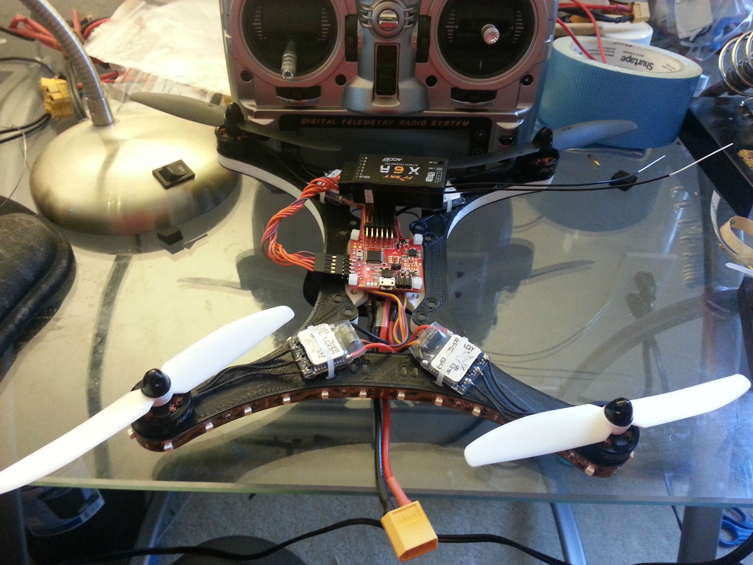
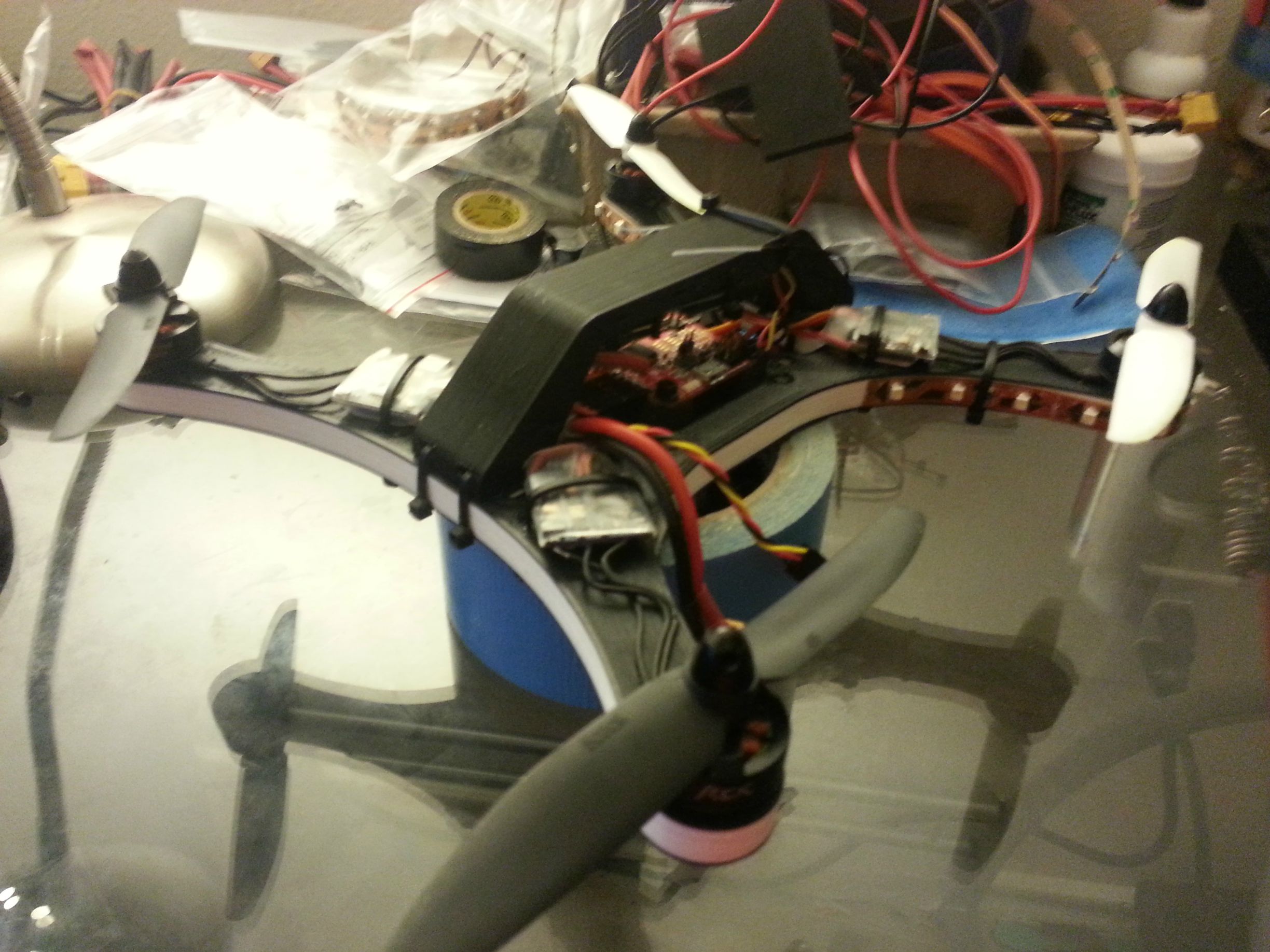
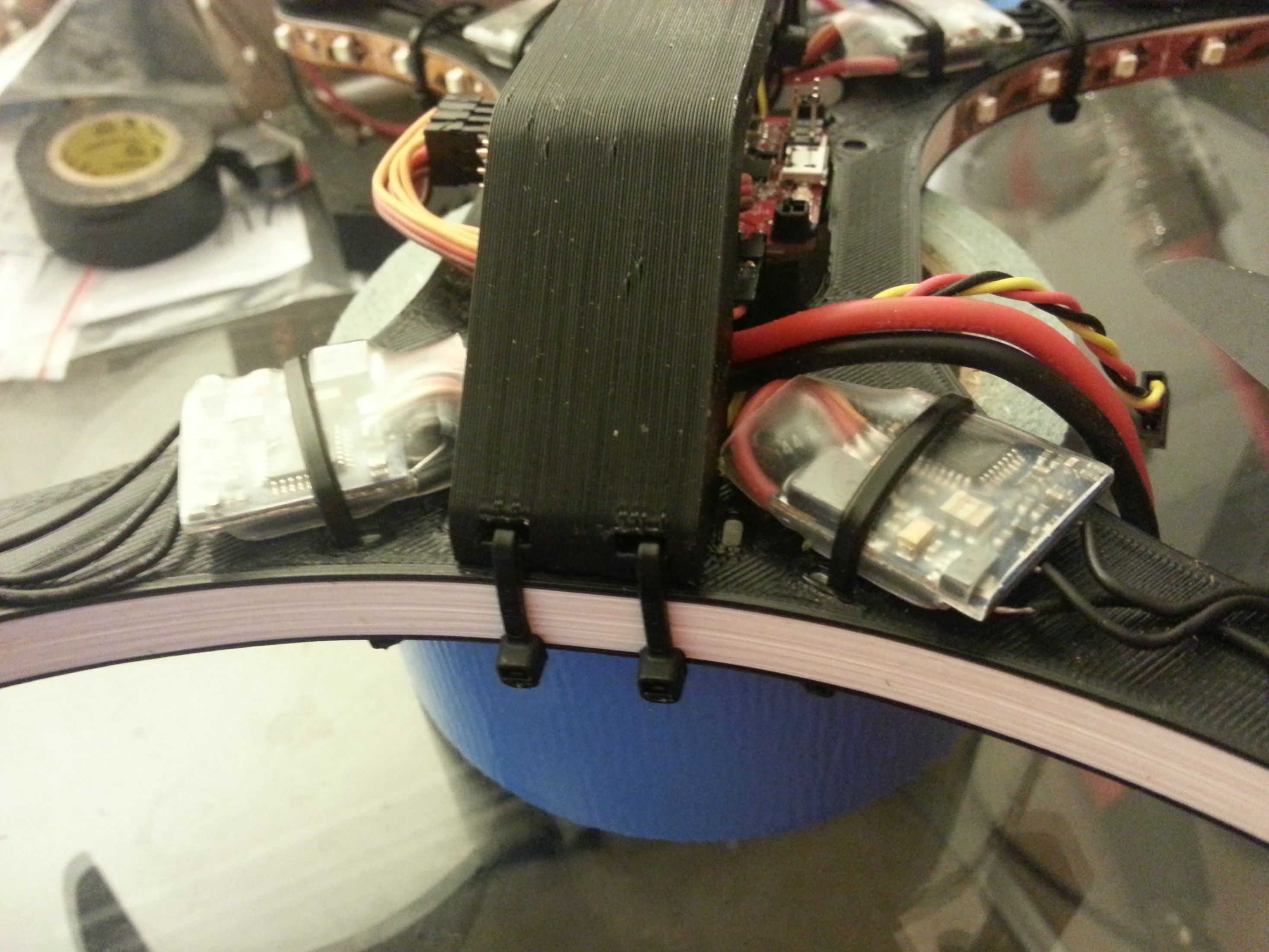
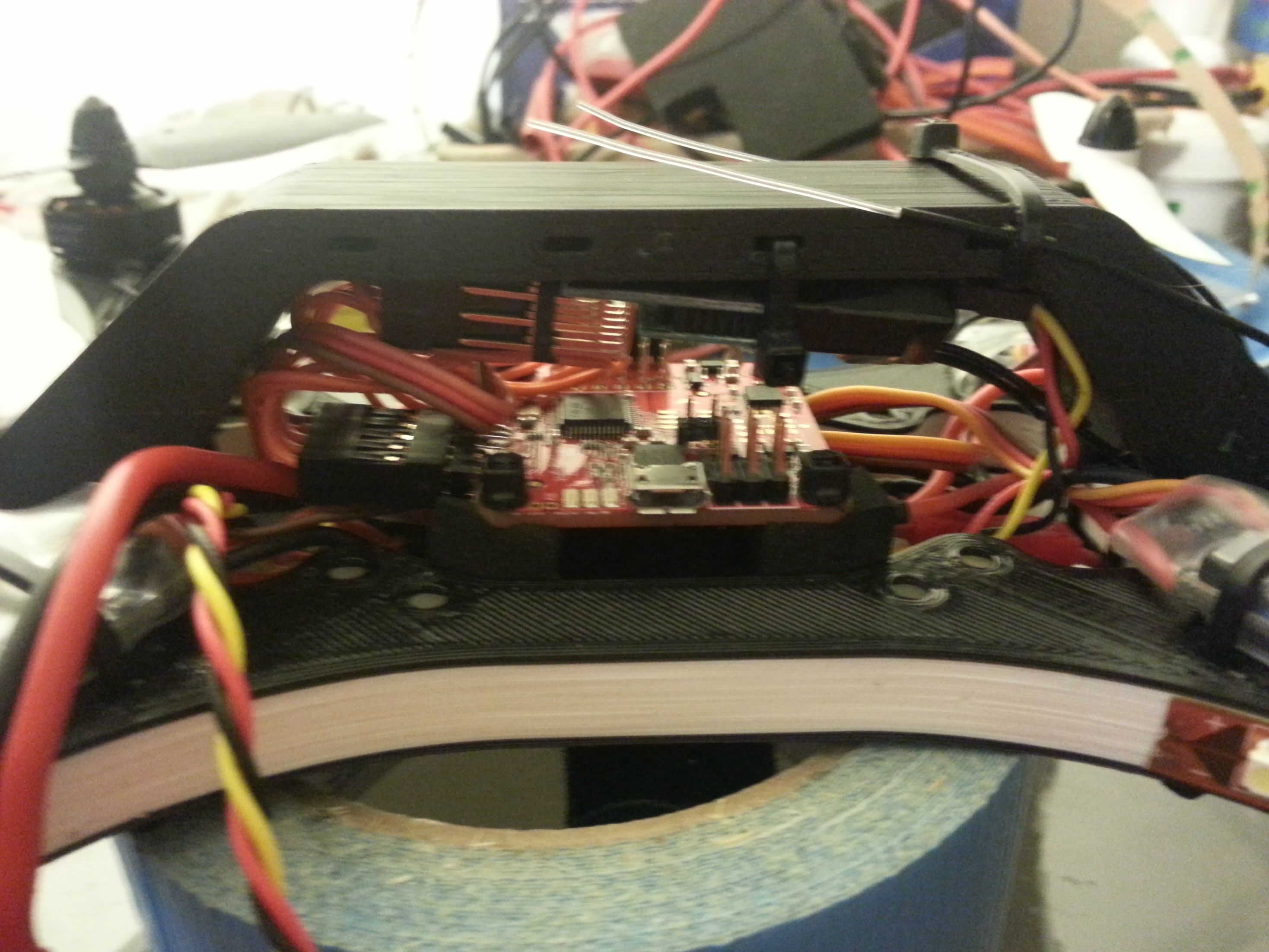
Flight Controller: Acro Naze32 (Sourced from MRSS)
Motors: RCX 1804 2400KV 7A (Sourced from RTFQ)
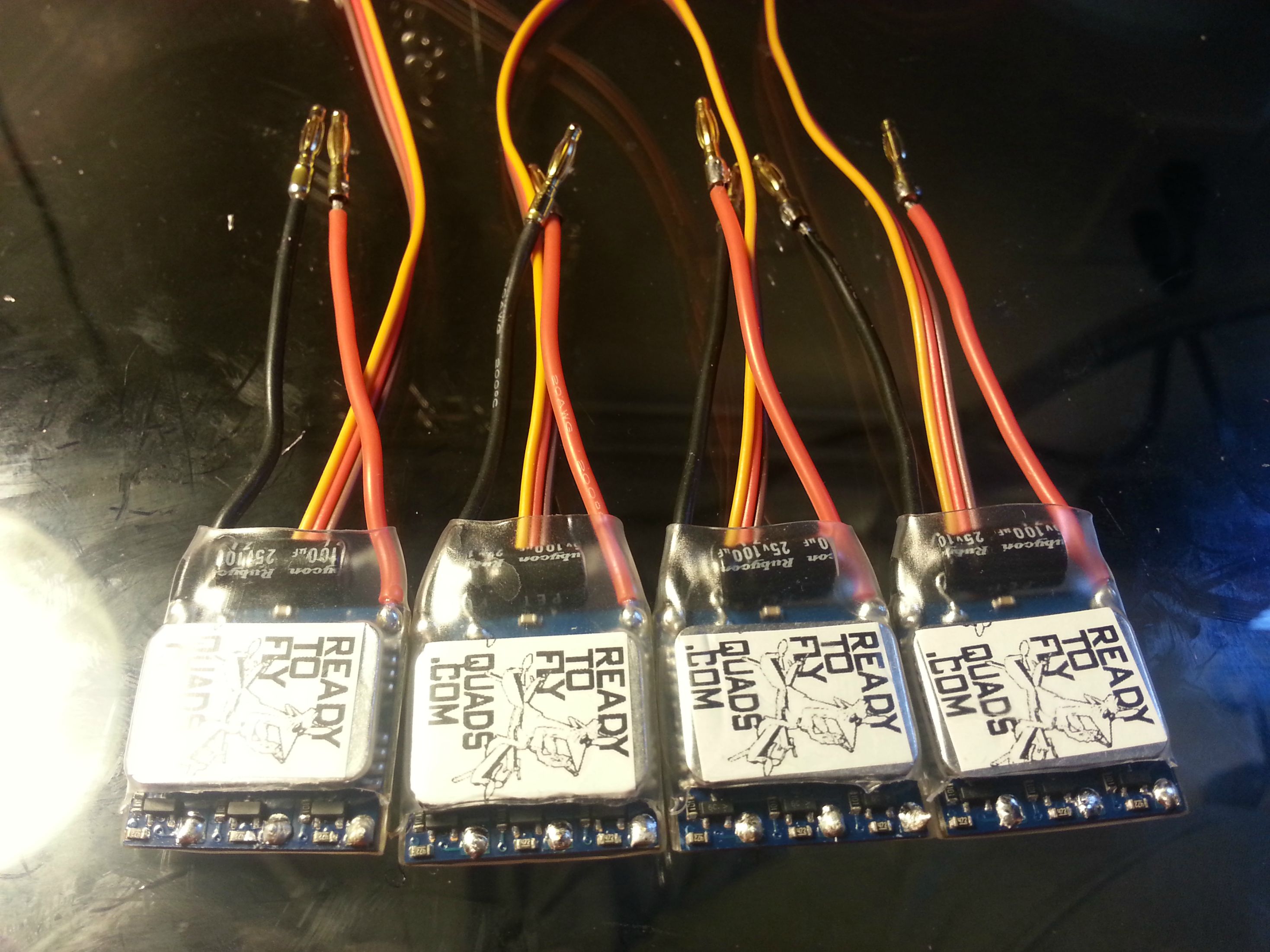
ESCs: B-12A Ice Blue Series with SimonK (Sourced from RTFQ)
Props: 5030 Two Blade Nylon CW & CCW Pairs (Sourced from X Hover)
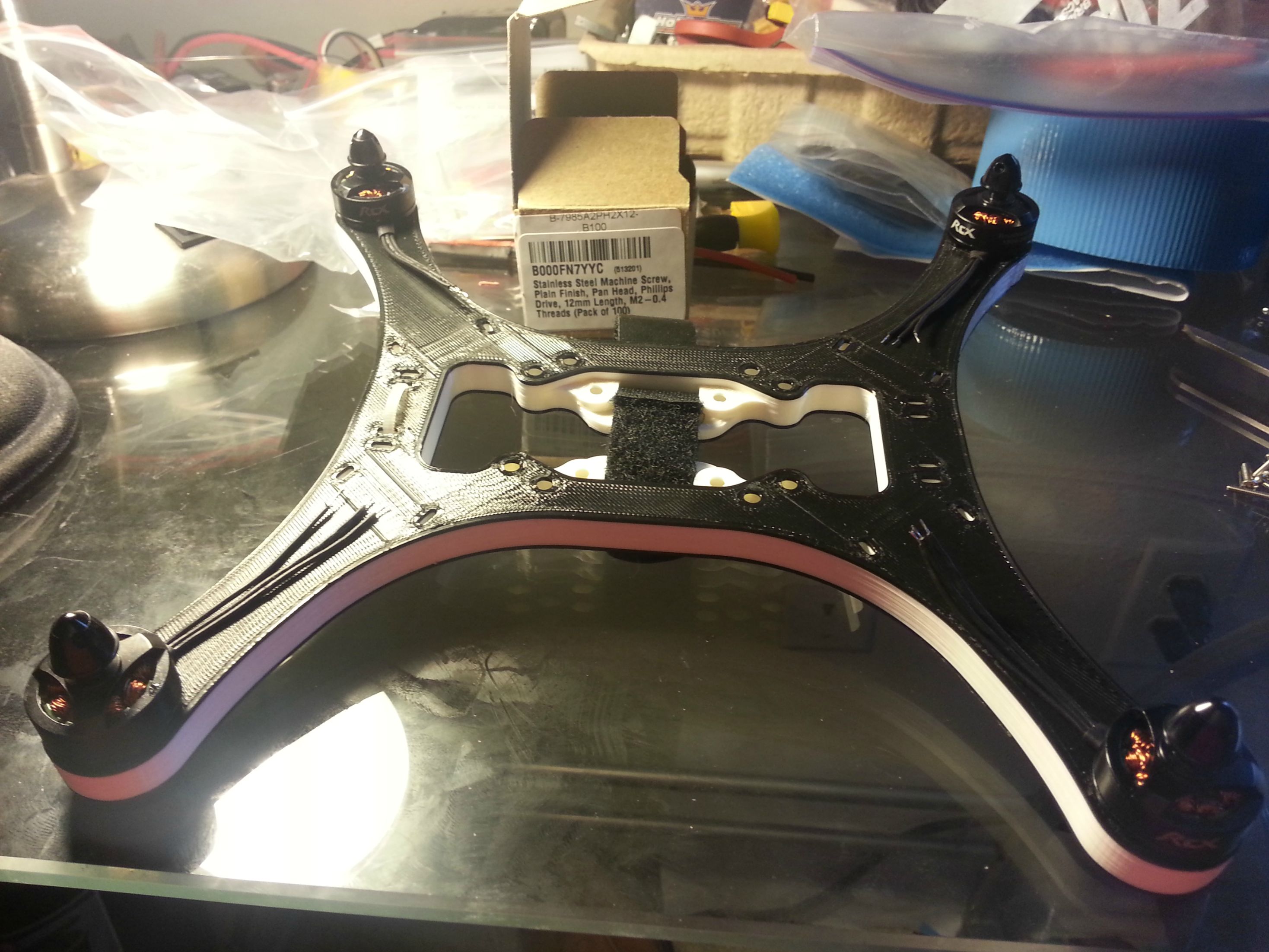
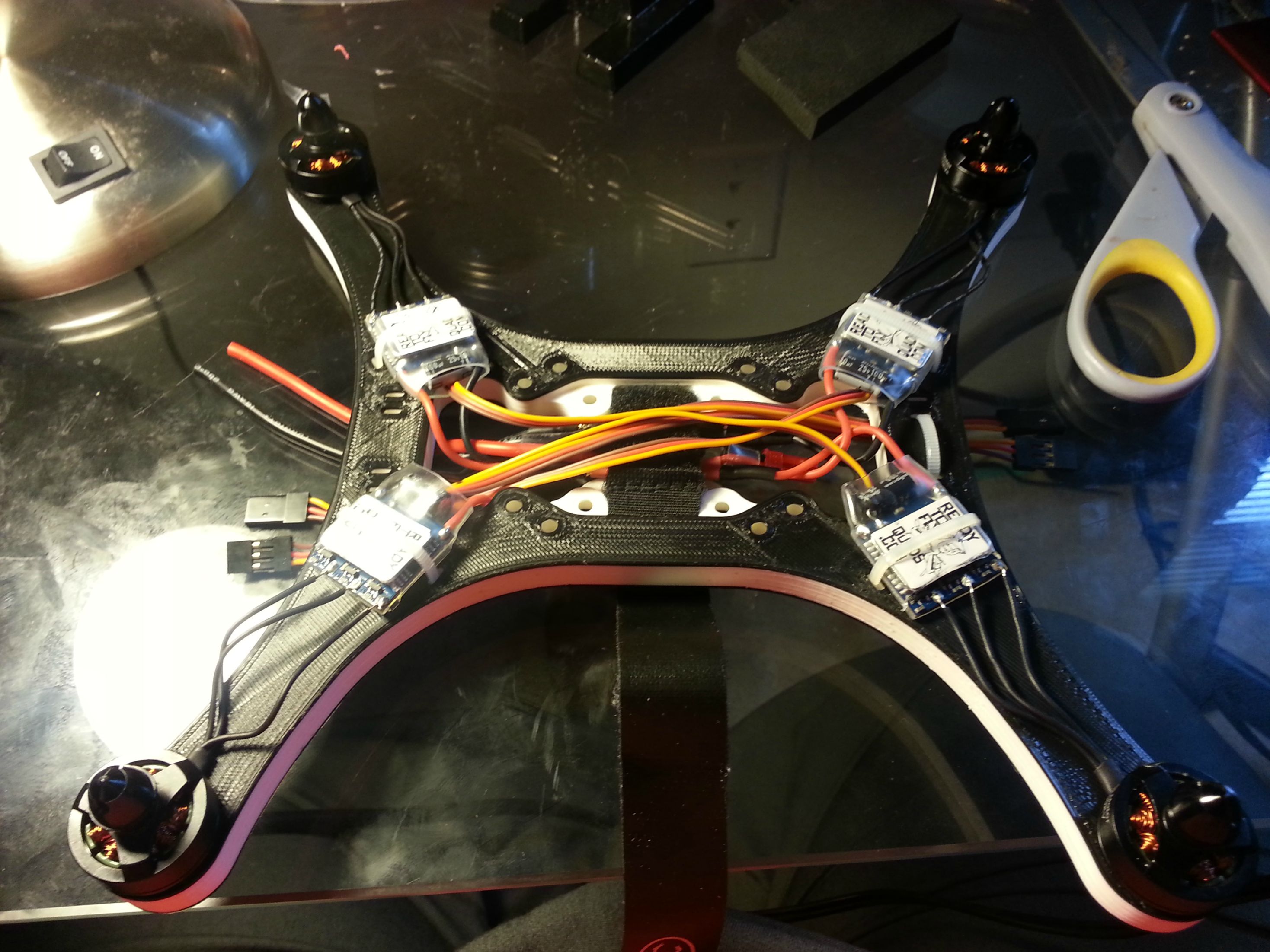
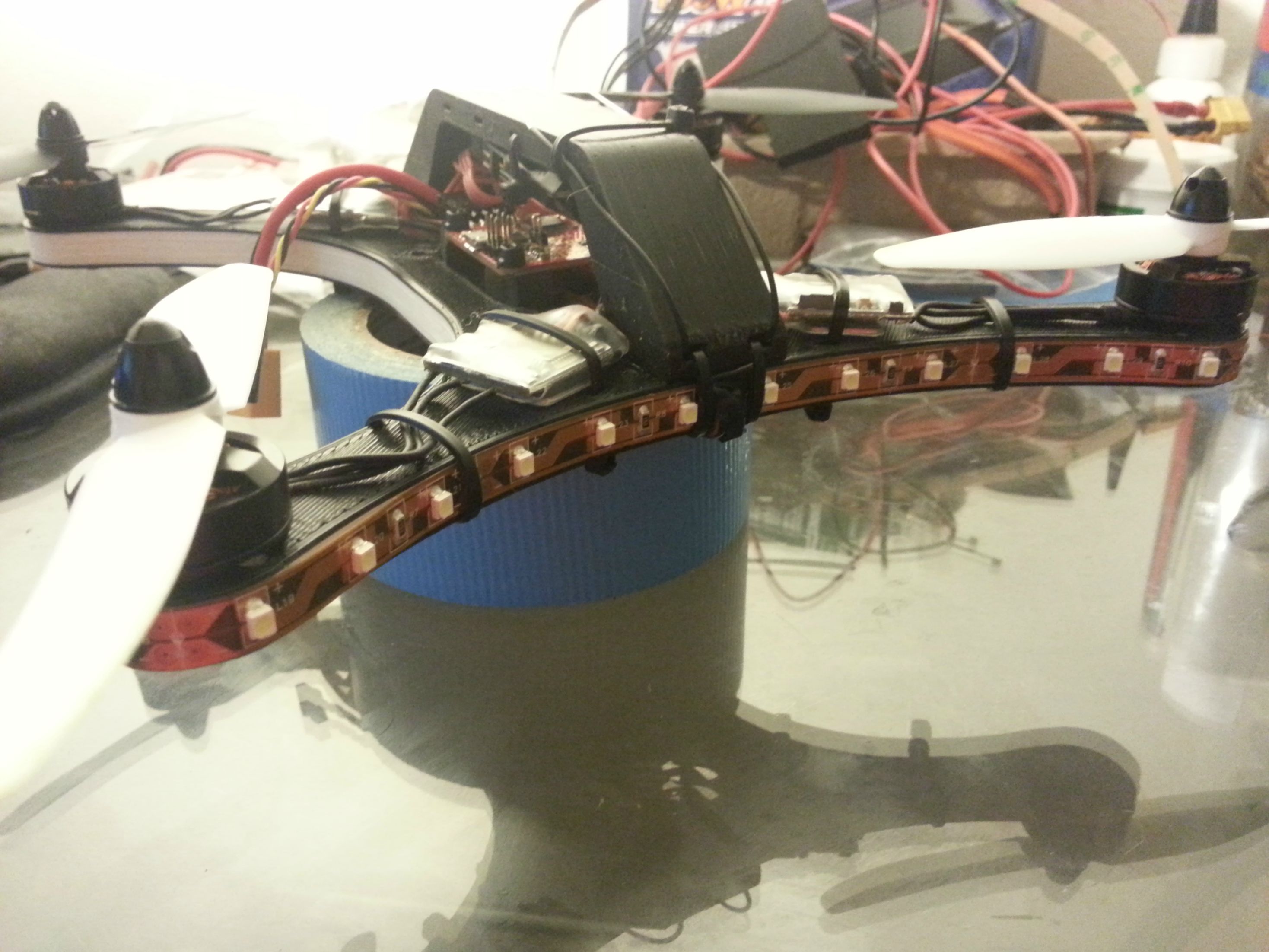
Frame: Polakium Engineering SSHQuad v3 with Roll Bar and Landing Feet
Receiver: FrSky X6R with Voltage and Current Telemetry Sensors (Sourced from RMRC)
Battery: 1300mAh 3S 35C LiPo (Sourced from MRSS)

Since Cranial let the cat out of the bag in one of the other threads, I thought I would go ahead and get this started. I expect everything should arrive on Friday, so I hope to spend most of Saturday building and Sunday flying the new little guy. I will take pictures along the way and expand on little things which differ from building larger FT multis.
 
Last edited:

FinalGlideAus

terrorizing squirrels
Let us know how the battery goes. I know the cheap HK batteries around that c rating can't handle being flown hard on that kind of setup so it will be interesting to compare. I'm running a 30c dualSky on my WQ which is holding up well where as a nanotech at that rating would dead by now. You may pay more elsewhere buy a lot of the time it lasts for much longer.
 

DDSFlyer

Senior Member
Probably a good thing you didn't get the HK racing quad, a friend of mine just got one and is having all kinds of problems getting it to fly stable. Looks like it's the crap Multistar ESC's that are the issue so he's getting some RTFQ SimonK ESC's and trying to get it to work...
 

Mustang7302

Senior Member
Let us know how the battery goes. I know the cheap HK batteries around that c rating can't handle being flown hard on that kind of setup so it will be interesting to compare. I'm running a 30c dualSky on my WQ which is holding up well where as a nanotech at that rating would dead by now. You may pay more elsewhere buy a lot of the time it lasts for much longer.

Tinkering around with my F330 this evening I flew one of the new 1300's on it, just for the sake of the shorter run time while I was testing the voltage and current telemetry sensors. On a fresh pack I saw about 10.5 amps of current to hover, then towards the end after 1100mAh was consumed the quad was pulling a little over 12 amps of current to hover. Once I set it down the voltage climbed back up .5 volts after about 30 seconds. This is on a 330mm size quad, running Turnigy SK3 1275 KV motors, 8045 nylon props, and an all up flying weight in the neighborhood of 650 to 700 grams. So we can assume there was on average 3 amps of current per motor to hover the craft. Once you start doing aggressive climbs or moderate to aggressive swooping about, the current consumption will go up. However I more or less think it the pilot would be hard pressed to make the average current consumption over the course of the flight be greater than four amps per motor for this scenario (rig).

I have been a fan of the Zippy Compact 2200mAh 3S 25C batteries from HK. They're cheap (<$10), do what I expect them to do, and I have yet to have one become unbalanced of the course of six or so months. The two Turnigy Nano Tech 1800mAh 3S batteries I flew did not last nearly as long without puffing (my fault, ran too long without alarm) or becoming unbalanced from cell to cell. I don't think the shorter life span on these batteries has anything to do with the C rating, it has to do with quality and enduring mild abuse.

It will take a while to see how these MRSS 1300's will perform over the long run. With any luck they'll be as reliable as the Zippy Compacts I still run. On the Polak Quad there will be even less current in the power plant, so these 35C batteries are plenty safe. They are more expensive though ($16), but it keeps me from giving my money to Hobby King. I will say though, the discharge leads and the balance plug leads are too short by at least two inches (5cm). You can work with them just fine, but I am spoiled to the generous wire lengths on the Zippy Compacts.

Probably a good thing you didn't get the HK racing quad, a friend of mine just got one and is having all kinds of problems getting it to fly stable. Looks like it's the crap Multistar ESC's that are the issue so he's getting some RTFQ SimonK ESC's and trying to get it to work...

I was going to try the kit out of the box as specified. If I wasn't happy with the stability or manueverability, I was already expecting to toss the 10A Multistar ESCs. The Blue Series from RTFQ is what I will be running on this Polak build. I expect I wont have any issues out of them and will pair well with the Naze32.
 
Last edited:

FinalGlideAus

terrorizing squirrels
Yeah it sounds like they'll be a good battery for you. I only brought it up because some of these mini motors can really draw the amps. My Warpquad draws 3a total during hover but between 60-70 peak amps at WOT. You could put a Zippy Compact on there and putt around all day without a problem but with the flying I do they wouldn't last more than a couple of flights before puffing. The nanotechs hold out a bit longer. The Blackout pilots are finding that even though they don't puff the zippy's (because they're only using 5x3 props) the voltage drop is too extreme at the end of the pack and all performance disappears. It's all down to how you fly as well as the copter their in. When pushing the packs, c rating counts. A 1000mah 3cell would be perfect for the WQ but try finding 60c 1000 3s.

I'm really keen to see how your little quad performs. It should fly!
 
Last edited:

jhitesma

Some guy in the desert
Mentor
Glad to hear the zippy compacts have worked well for you. I haven't had such luck with my zippy 2200 40c's (not the compacts.) They were great for a month or two but then started having cells get out of balance. I never ran them low and have treated them exquisitely but after just a few months of being flown every other day or so they're just not very happy anymore. I thought about trying a few of the compacts but after how these have performed I was kind of glad to see the compacts out of stock when I was battery shopping so they wouldn't temp me ;)
 

Mustang7302

Senior Member
Yeah it sounds like they'll be a good battery for you. I only brought it up because some of these mini motors can really draw the amps. My Warpquad draws 3a total during hover but between 60-70 peak amps at WOT. You could put a Zippy Compact on there and putt around all day without a problem but with the flying I do they wouldn't last more than a couple of flights before puffing. The nanotechs hold out a bit longer. The Blackout pilots are finding that even though they don't puff the zippy's (because they're only using 5x3 props) the voltage drop is too extreme at the end of the pack and all performance disappears. It's all down to how you fly as well as the copter their in. When pushing the packs, c rating counts. A 1000mah 3cell would be perfect for the WQ but try finding 60c 1000 3s.

I'm really keen to see how your little quad performs. It should fly!

60 to 70 amps out of a 1000mAh battery is just too much to ask, period. A sustained current for even 30 seconds would exhaust the battery's capacity, if it didn't burn up or other wise alter the chemistry of the cells.

I don't plan on this quad to be as outrageous as a WQ running SS X2204S motors with 6030 props on a 3S battery. But I think it will still be plenty peppy to diddle around with flips, rolls, and high speed passes.
 

Mustang7302

Senior Member
My order for 5030 props and 2mm bullet connectors from X Hover came in today. Ordered Tuesday morning, they were delivered Thursday afternoon. Only reason I ordered with them is because they had the color combination of props I wanted in stock; but they also had great service! So I thought I might get a jump on a little soldering by making the power manifold.

So you have to get power from one wire lead to three, four, six, and eight sources of load. This doesn't even consider auxiliary leads to power things like FPV equipment, LED lights, or even monitor voltage. There are printed circuit distribution boards are that easy enough to use for this, but they limit what you can put where and space is sometimes a consideration. The more DIY route is to build a wire harness with enough leads to fit your needs, but sometimes these can get pretty bulky. I took inspiration from looking at the parts included in the HK Spec FPV250 ARF kit and noticed that they provided what I best label as a power manifold. This manifold had eight 2mm bullet connectors joined together in a small and simple package; this would allow the ESC wires to plug into the manifold and still had open slots for auxiliary use.

However, I didn't order enough bullet pairs for a total of 16 ports. I only ordered 10 pairs, so got a little creative on how to best utilize this limitation. I decided I would do four ports, plus a fifth which would sit on top and allow the battery lead to come in on one side and on the other side would be a JST lead for auxiliary sources.

First up was joining the bottom layer together. I got a piece of double sided carpet tape (think duct table, but double sided) and stuck it to my desk. I then arranged the female bullets so the backs were facing each other and had a left and right side.

1OvyYiF.jpg


I slowly warmed up the bullets till they would take solder. I made sure to use enough solder so there was enough to join both left and right pairs together, but also join the two sides together. Then I went ahead and laid the top bullet in the middle-ish and did the same thing and making sure there was good solder connections to all four bottom bullets. I then went ahead and soldered a battery lead and the JST lead to the top bullet.

ucu4xqP.jpg


Wrap with heat shrink when done and you have a very compact power manifold you can tuck into anywhere.

HQx00mF.jpg


The FrSky current sensor goes in line between the battery and the power distribution to monitor amperage draw and calculate battery consumption during the course of the flight. Only draw back is that it is a bit bulky for small rigs, so I left the leads long so I can decide where I am going stick it and have access to plugging in and disconnecting the battery. Conveniently though it does have XT60 connectors built in it, so no DIY hacking needed.

Also pictured is a very simple little FrSky analog voltage divider which will report back real time battery voltage. I will wire it into the XT60 connectors which join the current sensor to the power distribution on the quad to keep from making a specific power source for it.

The props in the background also provide a glaring hint of the color theme of this build, which compliments the Polak frame I ordered. Since Cranial likes to name his builds, I have decided this build will be named "Mini Panda."
 

jhitesma

Some guy in the desert
Mentor
That's the basic idea I used on my power harness: http://forum.flitetest.com/showthread.php?6236-Ultra-budget-quad-build&p=70978&viewfull=1#post70978 I didn't take any photos of it going together though :( It's worked really well and hasn't given me any issues. I do wish I had thought ahead and provided a few extra connections though. I added up just tacking in some wires for my LED's and battery sensor later.

I did later re-position mine from the booms to the plate once I put a plate in: http://forum.flitetest.com/showthread.php?6236-Ultra-budget-quad-build&p=71780&viewfull=1#post71780 And better photos of it here after I added the tap wires for the LED's and voltage sensor: http://forum.flitetest.com/showthread.php?6236-Ultra-budget-quad-build&p=75469&viewfull=1#post75469

It's worked out really well and hasn't given me any problems. The only catch was building it in the first place was kind of a pain. That's a lot of metal to heat up and while my iron is great for small stuff...it's not very good at big stuff. I almost grabbed the big iron I use for stained glass but eventually got it with the little iron. If I build one like that again I think I may try heating the pieces in an oven or hitting them with a torch to pre-heat them. The other issue is just holding them in position while soldering them. I didn't try tape because I figured it would just melt from the heat. I tried clamping them in a vice but there was enough variance in size between them that the vice couldn't hold them well. So I ended up just doing it freehand with a lot of patience and a steady hand.

Hmm...wonder if HK has read my thread (they haven't given me any credit for the links to their products in it!)
 

Tritium

Amateur Extra Class K5TWM
My last power harness was built in Hobby King Fashion, 2 wires in, 8 wires out but rather than fighting with soldering the connection of 10 wires (5+ and 5-) by wrapping with a thin strand of wire as David W. does, I cut some small copper tube about 1/2 inch long then crimped each + and - connection of 5 wires (1 from battery and 4 to esc's) before soldering. What a joy to make it this way.

Thurmond
 

Mustang7302

Senior Member
That's the basic idea I used on my power harness: http://forum.flitetest.com/showthread.php?6236-Ultra-budget-quad-build&p=70978&viewfull=1#post70978 I didn't take any photos of it going together though :( It's worked really well and hasn't given me any issues. I do wish I had thought ahead and provided a few extra connections though. I added up just tacking in some wires for my LED's and battery sensor later.

I did later re-position mine from the booms to the plate once I put a plate in: http://forum.flitetest.com/showthread.php?6236-Ultra-budget-quad-build&p=71780&viewfull=1#post71780 And better photos of it here after I added the tap wires for the LED's and voltage sensor: http://forum.flitetest.com/showthread.php?6236-Ultra-budget-quad-build&p=75469&viewfull=1#post75469

It's worked out really well and hasn't given me any problems. The only catch was building it in the first place was kind of a pain. That's a lot of metal to heat up and while my iron is great for small stuff...it's not very good at big stuff. I almost grabbed the big iron I use for stained glass but eventually got it with the little iron. If I build one like that again I think I may try heating the pieces in an oven or hitting them with a torch to pre-heat them. The other issue is just holding them in position while soldering them. I didn't try tape because I figured it would just melt from the heat. I tried clamping them in a vice but there was enough variance in size between them that the vice couldn't hold them well. So I ended up just doing it freehand with a lot of patience and a steady hand.

Hmm...wonder if HK has read my thread (they haven't given me any credit for the links to their products in it!)

Oh cool. Didn't even notice that in your build thread; there was a lot of content and didn't read it all :(. Do you use an intermediate wire between the "manifold" and the connectors to the ESCs, or did you just lengthen the wires from the ESCs with out the intermediate disconnect bullets?

I was mostly drawn to this idea for the size of quad it is going on. If it was for a bigger 330mm or 450mm frame, I don't know if I would use this manifold method; it depends on how much wire the ESCs had I guess. I am all for simplicity.

I use a Weller SP80L 80W iron with a big wide chisel tip. Plenty of power, and good surface area to help penetrate heat for wire soldering. I've been known to do delicate soldering with it too using one of the corners with a lot of care and if I have enough room to get the iron in where it needs to be.

Oh, and the double sided tape idea was a stroke of brilliance when I started thinking of how I was going to keep things together while they were being soldered. I wasn't looking forward to chasing rolling connectors around or making some kind of jog to hold things for something that should be more than 10 minutes of soldering.


My last power harness was built in Hobby King Fashion, 2 wires in, 8 wires out but rather than fighting with soldering the connection of 10 wires (5+ and 5-) by wrapping with a thin strand of wire as David W. does, I cut some small copper tube about 1/2 inch long then crimped each + and - connection of 5 wires (1 from battery and 4 to esc's) before soldering. What a joy to make it this way.

Thurmond

I greatly dislike the four into one Y style power harnesses. They're too bulky and hard to finagle in small spaces to keep things tidy. I either do a daisy chain between bullets or cut out the insulation from the center from two long wires and join them in the center with a third lead going to the battery. These make for less bulk and more flexibility to conceal wiring.

"What a joy to make it this way." ... Was this meaning the manifold method is easier, or just using the pre-built Y style harness?
 

Mustang7302

Senior Member
I also tinkered with the telemetry on the Taranis this evening. Flew the F330 in a hover just to get a base line of what the data would look like. Data samples every half second or so created 700 data points in 5 minutes and 45 seconds. Fun fact, Excel only plots 255 points of data in a chart; ended up removing two thirds of the data to get the charts.

DJI F330 Frame
Turnigy SK3 1275KV Motors
DJI 18A Opto ESCs
8045 Nylon Props
DJI Naza M-Lite with GPS
1300mAh 35C 3S Battery
FPV hardware on board, Not plugged in
750 grams of all up flying weight

iL86jJK.png


I think it will be more interesting to see how these graphs look when actually flying around and not hovering in a small space. Here is a link to the the raw data in an Excel file if anyone is interested in seeing the raw numbers.
 

jhitesma

Some guy in the desert
Mentor
Oh cool. Didn't even notice that in your build thread; there was a lot of content and didn't read it all :(. Do you use an intermediate wire between the "manifold" and the connectors to the ESCs, or did you just lengthen the wires from the ESCs with out the intermediate disconnect bullets?

The curse of being long winded :D The wires on the 10a multistars I used originally were long enough to just work without me adding any extra length anywhere. It was a bit of a stretch and there was no extra length to spare...but it worked on my stock knuckle frame. When I switched to the blue series I found that their power wires were a little shorter. So I ended up desoldering the power wires from the multistars and just adding them to the blue's for extra length. It was an ugly solution since the wires from the multistars were much high gauge and rated for considerably less current. But I figured with my little 24g motors there's no way I'd be drawing enough to matter. When I upgrade to bigger motors I'll swap to thicker wires as well. In fact my HK order that went through customs hell finally arrived yesterday (almost a month after I ordered totally destroying my faith in swiss post and the 7 days from HK delivery I had come to expect from them.) and it has a few meters of suitable wire I ordered in anticipation of stepping up to bigger motors.

I was mostly drawn to this idea for the size of quad it is going on. If it was for a bigger 330mm or 450mm frame, I don't know if I would use this manifold method; it depends on how much wire the ESCs had I guess. I am all for simplicity.

Yeah, I came up with it without having seen it done anywhere else by trying to figure out the smallest cleanest wire to build a wiring harness for the knuckle due to the limited space. Really works well for smaller setups.

I use a Weller SP80L 80W iron with a big wide chisel tip. Plenty of power, and good surface area to help penetrate heat for wire soldering. I've been known to do delicate soldering with it too using one of the corners with a lot of care and if I have enough room to get the iron in where it needs to be.

I have a Hakko clone similar to the one hobbyking sells but I got mine from a place here in AZ about 12 years ago:
http://www.dunephotos.com/Electronics/MB-Projects/461393_FXGR3b#!i=18649511&k=pfBKQ6f

I do a lot of fine surface mount soldering so I usually have a fairly fine tip on it - but even for larger surface mount I enjoy a somewhat larger tip. Unfortunately 2 or 3 years ago I picked up a new genuine hakko tip and put it on but the heating element got wedged on it really tight and I haven't been able to get it off out of fear of breaking the heating element. I finally found my spare element so now even if I break it I'm just out the element and the tip...but I'm still in no great hurry to swap back to my larger tip since for most things the tip I have now works great. I have some magnified photos of the various tips I use next to the size of pads I use them on here:
http://www.dunephotos.com/Electronics/SDR/Janus-Construction/2946190_RfJmwN#!i=159355056&k=bSsVcLF

Oh, and the double sided tape idea was a stroke of brilliance when I started thinking of how I was going to keep things together while they were being soldered. I wasn't looking forward to chasing rolling connectors around or making some kind of jog to hold things for something that should be more than 10 minutes of soldering.

So it didn't become a melty sticky mess? That was what scared me off from trying it. I could just picture the tape and adhesive melting and making a huge mess.

I like the idea of using a small copper pipe crushed around them though...that could hold them in place and give good surface for the solder to get some capillary action going and really wick in there and make sure things are well connected electrically and mechanically. I may have to try that next time I build a power harness.
 

Mustang7302

Senior Member
So the order from Polakium Engineering came in today, ordered this past Tuesday morning. The order of motors, ESCs, and LEDs from RTFQ also came in today, ordered last Thursday night of last week. I spent a few hours putting things together and have already flown three batteries on the little guy. Build notes coming up here shortly.

So it didn't become a melty sticky mess? That was what scared me off from trying it. I could just picture the tape and adhesive melting and making a huge mess.

The tape did get a little soft and some of the adhesive did stick to the bullets when I pulled them up, but it wasn't messy by any means. I didn't even bother cleaning the junk off because it was going to be covered by the heat shrink.
 

Mustang7302

Senior Member
First order of business was making sure the motor mount holes in the frame lined up with the holes in the base of the motor; no issues there. Used two M2x12mm screws and M2 flat washers (sourced from Amazon) to affix the motors to the frame. Also went ahead and put in the battery strap so it wouldn't be forgotten later (Cranial).

Fx1461M.jpg


Next steps were to prepare the ESCs by soldering on the male 2mm bullet connectors to the battery side of the ESCs and removing the motor leads which came pre-attached. Oh, and don't forget to heat shrink the bullets (not pictured below).

XPbqDUE.jpg


I mocked up the ESCs to the mounting slots in the frame for the zip ties and made sure all the wires were going to be long enough; luckily everything was just the perfect lengths. After making note of motor spin direction I then proceeded to soldering the motor leads to the ESCs.

Tip: more times than not, if you keep the wires from the motor to the ESC parallel the motor will spin CCW; crossing any two from all being parallel will spin the motor CW. This takes some of the guess out of the process.

vnHqhMA.jpg


The power distribution manifold fits better than I could have hoped between the frame rails and just below the battery strap. Sometimes, you get lucky. Note: the power wires are not pushed in all the way just for the sake of mock up.

There is a piece of foam between the positive and negative manifolds for two reasons. One, it helps keep the parts from wanting to fall below the frame rails. And two, more importantly, a little extra security to keep them from shorting out.

tUj81Ce.jpg


I went a head and temporarily mounted and wired up the flight controller to the frame so I could connect it to the PC and go through the few setup steps. White 4" zip ties were used for mocking things up; they don't end up hanging around for too long.

First thing I do with Baseflight Configurator (the Naze's PC utility) is enable a feature called Motor_Stop, this keeps the motors from spinning while armed. Next I went ahead and calibrated the throttle range for the ESCs by using the MinCommand; high limit set to 1950, low limit set to 1075, and operating MinCommand set to 1050. At this point I use the motor output tab in Baseflight to manually check the motors are on the right corner and are spinning the right direction. Then I went on to checking the receiver output to ensure each channel corresponds to the correct input on the Naze and alter the channel mapping as needed to ensure they're in alignment. Lastly I ensured the min and max range for the Pitch, Roll, Yaw, and Throttle channels were dialed in close to 1050 and 1950.

At this point the quad was ready to fly, but I killed a little time by attaching the LED strip while waiting for my kind wife to come home with some black 4" zip ties that I had asked for.

rF3vAh4.jpg


She wasn't home in time so I cheated and gave it a quick maiden to check things out. Strapped the receiver and battery into the batter strap, set it down in some open floor space, and eased into the throttle. It went up smooth as glass without any drama on the first attempt. Flew it around for six minutes and called it quits there because I didn't hook up a voltage alarm or the telemetry sensors yet. Battery wasn't even warm yet.
 

Mustang7302

Senior Member
The work wasn't done just yet there, there was a lot of tidying up to do. First order of business was to flip the ESCs over so the labels were face down; this was to remove the branding from view and give a flat surface for the ESCs to sit on against the top of the frame. Next I remounted the Naze32 with foam cubes (1cm x 1cm x 1cm), cut up from an old KK2 foam box, under each corner of the board and used Cranial's zip tie method for securing to the frame. ESC signal wires are tucked up under the flight controller keeping all of the wiring nice and tidy.

I attached the roll bar at this point with the hope that the receiver would fit under the roll bar with just enough clearance above the Naze32. But alas it did not. I ended up taking the receiver out of its plastic case which gave me just enough clearance. The roll bar conveniently has little slots in it to make it nicer to zip tie components to the bottom or top sides. I should also note that at this point I did not yet realize I mounted the Naze32 in such a way that I couldn't get to the USB port; later I ended up taking the top half aparts and remounting the board so that it was rotated 90* to the right. This change in orientation can be accounted for by setting the attribute align_board_yaw = 90. The FrSky X6R receiver I am using has two antenna coming out of it, which fit nicely through the mounting slots of the roll bar to the frame; just route the rest of the wire so it isn't in the way of moving parts.

The last little bits of the puzzle was adding a female JST connector to the LED strip and connecting it to the power distribution male JST plug and then finally wiring up the FrSky Current Sensor inline from the battery. This is when I took it out to fly a battery with some changes to throttle expo, yaw rate, and RC rate. I found that the total power consumption to hover was 5.5A, ran for 12 minutes on the 1300mAh 3S battery with mild maneuvering, and the all up flying weight is 390 grams. Hover occurs at the tick mark just below 50% on the throttle throw.

The last thing I want to mention before providing some pictures showing more detail is the landing feet, or lack there of. I tried the feet Polakium offers with the frame (sold separately) but found that a minor brush against the grass popped one of the zip ties holding it on and the copter was flying with three legs. A few minutes walking around the back yard and I ended up finding the lost foot. I then attached some 40mm long aluminum M3 standoffs I got from RMRC with the holes meant to mount a 45mm by 45mm flight controller. I wasn't too happy with this solution either because the 1300 just barely fit between the feet, which left no room for the current sensor to be strapped in next to it. I used these stand off feet as a level platform to calibrate the accelerators, then off they came. I will just fly the little guy without feet; I prefer the lower profile look anyways.

On to more pictures!

4jrsd8s.jpg


LqiG7or.jpg


LcuKgUo.jpg


rc93jM6.jpg
 
Last edited:

Mustang7302

Senior Member
I data logged the last flight to monitor current consumption and voltage. During the flight there was mild maneuvering around the back yard and short throttle jabs to climb up 50 feet, drop throttle to let it come down quick-ish, and then catch it before hitting the ground; you can see this happening a number of times at two points in the logging.

uEXHNVG.png


Raw numbers in Excel are available for download.