Reduction of propeller diameter by using a short duct or shroud.

OwenN

Active member
https://www.google.com/url?sa=t&rct=j&q=&esrc=s&source=web&cd=&cad=rja&uact=8&ved=2ahUKEwjmjcynvPntAhXazjgGHVdqCdkQFjAFegQIBxAC&url=https://www.semanticscholar.org/paper/Quadcopter-thrust-optimization-with-Kuantama-Tarca/7e8efcd65702837b7883182b94489c6d16412437&usg=AOvVaw2nJKvlNXK5CGcT8NHD8Wid
These people show a thrust increase with a tapered duct outlet.

I don't agree that propeller shrouds are any good on quadcopters-you want to fly at an angle, and not interfere with propeller performance when airflow arrives at an angle , as with a helicopter.

the claim is +19 % on thrust and +17% on blade ejection velocity over unshrouded.

This sounds a little contrived, as generally blade performance is good with good tip shape, and relatively low velocity (20 m/s)
I have found that power varies directly with diameter for the same thrust.

1/2 diameter = 2x the power., Also, increasing diameter by 33 % drops power required for the same thrust on the same motor,
assuming torque remains the same over the rpm range, rpm drops by about 60 %
Ie: 54 amps becomes about 36 amps.
Find change in diameter to keep the same thrust?- use area effectiveness, as thrust depends directly on area.
area reduces by 19 %, so diameter reduces by about 10 %. Does this sound right?
example calc: 0.9 sq = 0.81, 1-.81 = 0.19
9 inch diameter becomes 8.18 inches. I need to cross-check these results elsewhere, as their measurement methodology may be suspect.
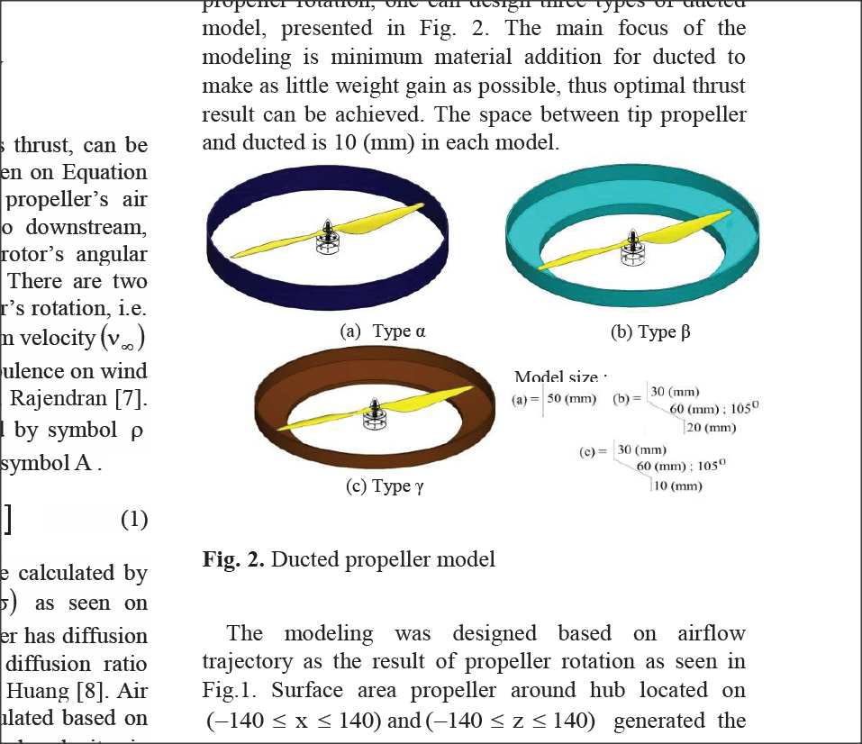
taper duct style.jpg
ve I I find it difficult to believe that constricting flow after the propeller improves efficiency. In free air, the flow naturally restricts to half the area and twice the velocity, anyway. Also, their tip clearance seems too great at 10mm over 400 mm prop diameter.
Also, they don't account for a curved inlet.
Other sources show that 10 % diameter reduction on inlet to the propeller diameter is desirable. for general flight.
Maybe a little outlet restriction matches into the free air conditions better.

The amount of restriction required reduces with increasing speed (V0, aircraft speed) , where V1 is the output velocity at the propeller.
Also, reducing the propeller diameter on a motor automatically increases rpm, until torque needed balances the engine torque again.
if A drops by 19%, V increases from 21 to 23 m/s for the same thrust,
power = TV = 1.1 times original, same torque, = 1.1 x rpm.
now 1.1x velocity also = 1.1 x rpm. If rpm was 8000, it will now be 8800, so we are now producing the same thrust plus an extra efficiency factor, which balances the power inefficiency factor.
Now this motor produces more thrust with less power by, one assumes, an 8 inch propeller? (the original motor table) - the table doesn't make sense- we need the original.
 
Last edited:

JasonK

Participation Award Recipient
@OwenN , with out reading the wall of text, how you get improved thrust with a shroud is 2 ways:
1 - by reducing 'tip spill'
2 - by increasing your effective 'airfoil' via the accelerated air over the top edge of the shroud.

this should be at least somewhat helpful:


as a secondary thing... have you built anything yet, I see lots of post about various theory stuff, some practical application of things can help learn the theory faster.
 

OwenN

Active member
Seen that. It basically says that ducts don't really do anything beneficial, that is worth making them in the first place.
You definitely shouldn't put then on drones. One of the tests seems to indicate some sort of thrust benefit, for a real weird cross-section profile, and I haven't found anything on "real world" inlet profiles yet. There is some indication that a 10 % lead-in by diameter is of benefit.
I am working on 9 inch vs 8 inch props at the moment, and whether I can trim the tips off a 9 inch, put it in a duct, and get the same thrust.
It looks like I get more thrust, more rpm, and more power consumption??-The motor just speeds up a bit.

At present the props are 9 inches, but I can trim them back to 8 inches (88%) in the duct.
The pointy tip doesn't do much, only reduces tip circulation.

He also said he would do some real world tests on number of prop blades. I haven't seen that yet. His explanation of multi-blade props was a bit suspect.

They only apply to engines that are maxed out, and you can't increase prop diameter, and you want to reduce prop pitch because your pitch speed is too high, or the blade loading is excessive - as per WW2 fighters.

Very high pitches are less efficient at static thrust.
I suppose a blade can only stand so much pitch-loading before flow starts misbehaving.
The same load can be spread over more, narrower blades, more efficiently, and at less pitch.

Also, fast -manoeuvring quad drones seem to get more "bite" out of 3-bladed props. 2-blade flow may be disrupted more by angled flow as in helicopters, or when rapidly swivelling the prop about-only one blade of 3 gets a decent "bite" at the air.

From the calcs I have done, props move over 75 % of the air predicted during static thrust, at 20-odd m/s (40 mph)
velocity ex the prop.

There is nothing to gain down low., for a particular pitch.

There may be more to be gained at maximum flight speed.

I see some planes with flattish-tipped scimitar 6-bladed props.

I really don't know what they were thinking, there.
The scimitar shape likely allows more blade width towards the tip.

It probably did something good in testing, and the rpms they run means they can't use a bigger prop diameter??
------
I need to clarify the prop specs for my motor. Does it need 8 inch or 9 inch props , 5 inch pitch, or something else??

I think it needs to make around 1N to run 9 inch, in the midrange. If it will pull 50-ish amps in mid range rpm , it should do that easily.
-see my motor spec thread - on the 2806.5 1800 KV, now 2808 1900 KIV.

For my model design,
I have a problem getting cog, thrust, and drag to line up. On that side, I may just go for curved inner wing panels, and
move the front and rear(third) wing up to suit.-somewhat further away from scale, though I don't think appearance will suffer.
Now to learn how to design a curved beam!

I have just been working out long wingtip cannons, like the x-wing fighter.
20mm leading into 10 mm carbon tube?
I can decorate with an x-wing-reminiscent paint scheme.

The whole layout looks a bit swoopy, semi-space-fantasy. - have you had a look? - there is a drawing in the wing loading thread.

I want red, white, black, yellow, but not as much white as the x-wing, though.
------
[quote/]
(Jason K)
as a secondary thing... have you built anything yet, I see lots of post about various theory stuff, some practical application of things can help learn the theory faster.
[/end quote]

I have brought the engines- I need to choose prop size, then I can start on the ducts.

I can also do engine mounts-just brought the aluminium.

I now have some further design revision and 'swot" to do on the wing. -this is all at 1/5 scale.

I have a vast amount of pattern-drawing to do before I cut any balsa-outside making bits for the motor pods and duct.

I could make some 1/16 balsa 2-ply, I suppose, using my 15 minute epoxy. I need to buy the slow stuff- $54 nz for 1.25 L-
should be tons!- motors are my last buy for this month, though. $114 nz.
 
Last edited:

leaded50

Legendary member
In general, 2-blade propellers are slightly more efficient. However, efficiency doesn’t propel an airplane, thrust does. Thrust is needed to overcome drag and weight, helping the aircraft climb.

Choosing the right number of propeller blades depends on certain parameters, including a given aircraft’s engine power, operating RPM for the propeller, diameter limitations, and performance requirements. If these factors are held constant, the efficiency of a propeller would decrease as more blades are added. However, as engine power increases, additional blades are generally required to efficiently utilize the increased power and produce thrust. Therefore, the most efficient number of propeller blades for an aircraft depends on the combination of these factors, which of course, will vary depending on the aircraft.
 

JasonK

Participation Award Recipient
if someone wants to put up the capitol to get the needed parts, I might be convinced to do something of the sort.
 

quorneng

Master member
OwenN
Don't forget full size reach a diameter limitation that is rare in most models. If the prop tips enter the transonic region the drag rises dramatically. In such a case power is absorbed but no extra thrust is created. To avoid this a reduction in diameter but multi blade to absorb the power becomes the only practical solution.
Multiblade props are not chosen for their efficiency but as a workable solution to a complex set of limitations.

A brushless motor is a 'constant speed' type. In other words for a given applied voltage it will reach a maximum rpm and go no faster. A load simply slows it down so it draws more amps. There is a maximum load (rpm) that the motor can handle before it over overheats and destroys itself.
The prop diameter & pitch (the load) has to be chosen to give the required aircraft performance but remain within the capabilities of the motor.
In general a brushless motor is limited by the amps it can handle not the voltage applied. Motor power is the product of the volts & amps.
It is not difficult to see that choosing a suitable (best?) motor/prop/battery voltage combination for a particular plane is quite a complex process.
Indeed there are so many variables at work that you can only get so far by using basic principles. Then it is down to simple trial and error.

Also remember a motor can overload for maybe a minute. The speed controller (ESC) being electronic is much more sensitive and is likely to fail almost instantly in a similar overload situation.
 

OwenN

Active member
I think performance gains are only at the envelope limit, with constant speed pitch-controlled propellers, not with model airplanes.
Maybe tiny props 6 inches and under might benefit at very high rpm??

Carbon fibre 2-blade 7s and 8s are the best in static thrust test results I have seen.
Nice pointy tips, optimised for speed.
Also some good glass composite ones.

Quadcopters use them for a different reason, because they are not so disturbed by very high angular rate turns.
if someone wants to put up the capitol to get the needed parts, I might be convinced to do something of the sort.

Bruce Simpson said he would do a report in 2016. I haven't seen anything so far. (rcmodelreviews you tube)

Possibly not so much up to fiddly manual work, nowdays. - he still does the "talking head" thing!
<edit>
I looked at one of his recent videos, and he is looking pretty good! The meds must be working!
 
Last edited:

OwenN

Active member
Just thought of another construction method: 1/16 balsa disks, spin and sand, frame, cover perimeter with 1/16 balsa,
add layer or 2 layers of fiberglass/resin, knock out center webs, keep the balsa ring!
This saves a finishing step and adding draw to the plug.
You have to do it twice, though.
Would it be an advantage to make 2-ply balsa for the disks? - They would sand more evenly?
Then just grain fill, sand, dope, sand, paint the insides of the ring.