Republic JB2 "Loon" An unusual EDF scratch build subject.

quorneng

Master member
The JB2 "Loon" was an almost exact copy of the Fieseler Fi 103 (better known as the V-1).
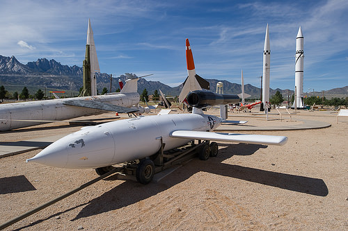
JB-2Loon2.jpg

40,000 were ordered to assist with the proposed invasion of Japan in 1945/6 but with the surrender after the atomic bombs the order was cancelled. Republic only headed the design team. The air frame was made by Willys and the pulse jet by Ford. About 1000 had been completed. Many were used experimentally in the years after the war.
It actually makes quite a good EDF. The air frame is simple but has low drag aerodynamics and the duct is both simple and completely external.:)

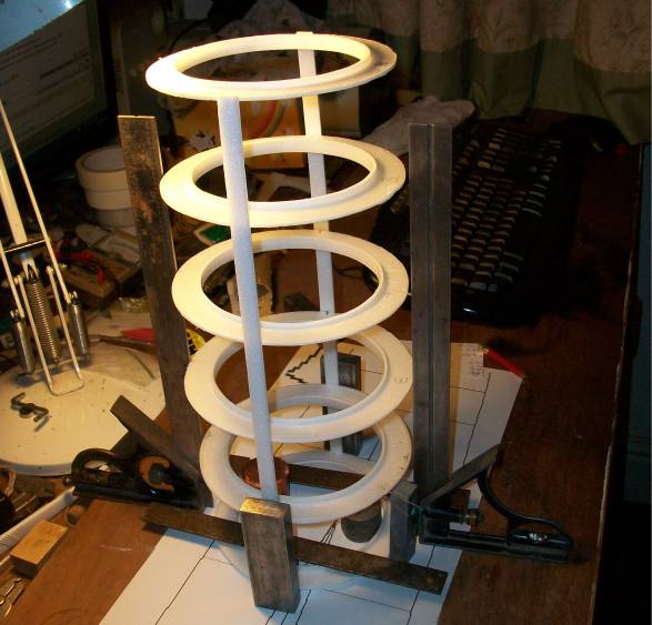
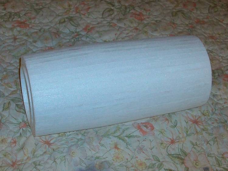
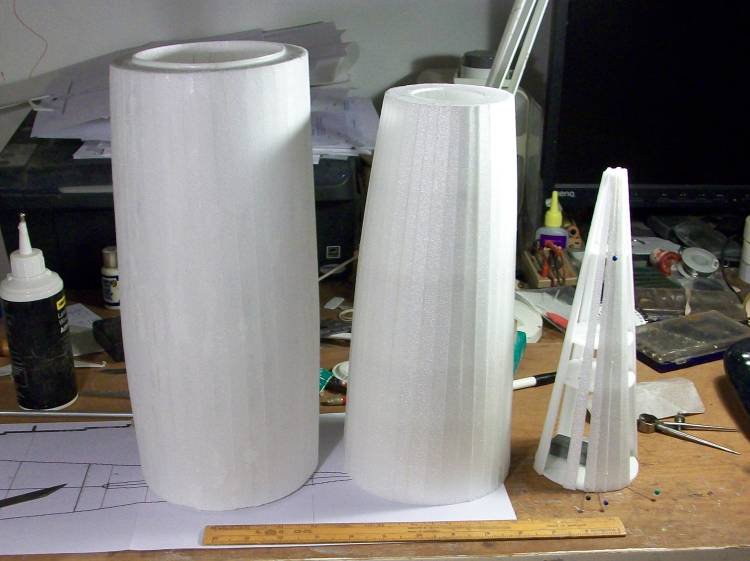
I decided on a 40" (1000 mm) span and to made almost entirely in 3 mm Depron with just a small amount of balsa in the wing, tail and fin which also supports the duct. A cheap AEO 55 mm EDF is positioned at the front of the pulse jet duct. A length of plastic gutter down pipe was used as "former" to build the duct around.
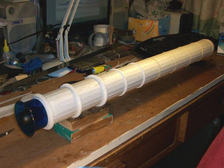
InnerDuct.JPG

Done like this means the exhaust portion of the duct is very long so was left a constant diameter to keep down the duct losses. I hoped that by retaining the EDF bell mouth a good static thrust figure could be achieved for what was hopefully going to be a fairly slow flying plane, for an EDF!
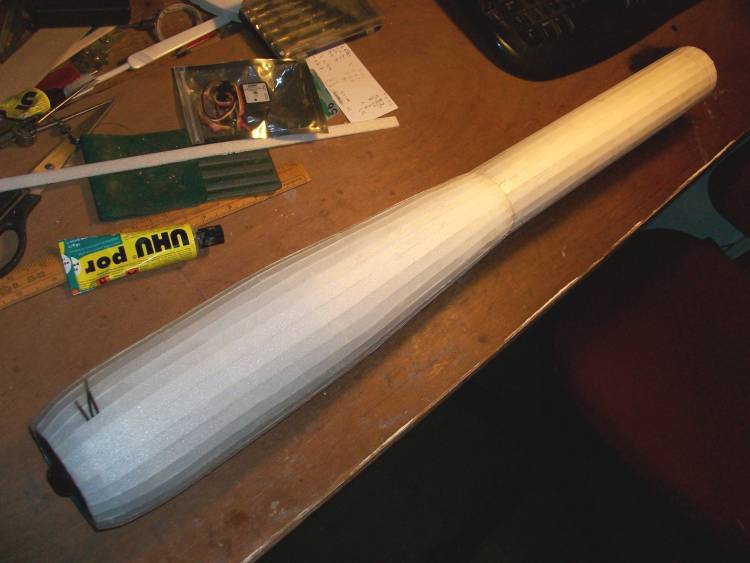
OutSkin3.JPG

With a completely separate duct meant the final thrust could be determined before even starting on the rest of the air frame.
It developed a bit over 16 oz thrust on a 3s. The aim was to keep the complete plane under 2 lbs all up.
To be continued.
 

leaded50

Legendary member
in scale by a plane length of 1000mm, you get approx. 644mm wingspan. and by the planned 50mm used EDF approx. 50% thrust in grams relative of the weight of plane, you gonna get trouble.. Gonna look great, but difficulty flying. A EDF needs min. thrust in grams as, or better than grams weight of plane.
I think also you gonna loose thrust by the long "thrusttube" at least after whats said .. recommended is around 3 -5 X edf.
Constant diameter im not agreeing on in my experience, though eg. 12blades are better, then eg. 5 blade EDF. Your drawing the air around a motor in middle, and after that with constant diameter thrust tube, you will still "uphold the place in airstream for motor" further on. Airstream cant do that much.. it increases velocity around the EDF motor, and if not taken in considetration at thrusttube by , you will loose that extra velocity not far after. You loose the increased accelerated speed of air after the EDF.
 
Last edited:

Pieliker96

Elite member
A EDF needs min. thrust in grams as, or better than grams weight of plane.
In my experience, this is most definitely not the case. The two EDF models I've built have had thrust-to-weight ratios of around 0.65 to 1. The first one flew fine and the second is slated for a maiden later today. Most full-scale aircraft have a thrust-to-weight of under 1 - they can't hover vertically, but can easily overcome the drag associated with lift in flight. While a higher thrust-to-weight would be certainly beneficial (especially for hand-launching, where immediate speed is needed), it can work fine if the flight speed of the plane is sufficiently low.

I think also you gonna loose thrust by the long "thrusttube" at least after whats said .. recommended is around 3 -5 X edf.
Thrust tubes are a complicated subject. I've always heard the "tube should be 3-4x fan diameter" rule but never found a source for it. In my own testing, omitting the thrust tube altogether was optimal for static thrust (This may not hold true for dynamic (in-air) thrust, which is much more difficult to measure). As far as geometry goes, I found the best (of the four tested) to be a cylindrical section up until the end of the motor bell with a constant taper to the exit area. I agree that some sort of taper - even just a short little nozzle at the back - would likely improve performance significantly.

eg. 12blades are better, then eg. 5 blade EDF.
From a theoretical standpoint, more blades reduces efficiency. That being said, the sound of a 12-blade is significantly more pleasing than a 5-blade. Thrust tubes can also help bring out the lower frequencies, adding to the "woosh" effect.
 

leaded50

Legendary member
From a theoretical standpoint, more blades reduces efficiency. That being said, the sound of a 12-blade is significantly more pleasing than a 5-blade. Thrust tubes can also help bring out the lower frequencies, adding to the "woosh" effect.

About 12 blade vs 5 blade... a 12 blade doesnt get as much interference on the thursttube type vs a %blade... foreg. 5blade its more critical, for best power.
 

quorneng

Master member
I am not sure I can accept that the number of blades makes any difference to the specific thrust tube losses (g/mm length) for a given air velocity. A 12 blade fan may be able to handle the back pressure better but it does use more power to do so but I do accept my parallel duct will loose a bit of efflux velocity and thrust but the fan will compensate a bit having a slightly larger mass flow so the dynamic thrust on a slow moving plane might be better than the small drop in static thrust might suggest.
The scale length for my 1000 mm span is very nearly 1500 mm. It will be a long plane.
The 2lb (900 g) all up weight at this stage is only a "guesstimation". Structures built using Depron as a stressed skin can be very light.
Foe example the complete 'pulse jet' body without the EDF weighs just 24 g. The 6 blade 55 mm AEO EDF is also pretty light at 62 g. It draws 24 A on a 3s so I hope to get away with using a modest 1800 mAh battery.
Construction of the fuselage gets under way. It is built in 4 sections (nose,centre and 2 for the tail) each as planked structure built vertically over Depron 'ring' formers. It is after all Mad (scratch) Builder's Corner.:eek:
Centre section first. Note the internal flange on the formers that in effect creates an "I" beam section as the skin goes on
FuseCntr1.JPG

To prevent generating a "banana" the planks are carefully added on alternate sides.
The Centre section complete
CntrFuseFin.JPG

There is not a lot inside!
CntrFuseInt.JPG

Not quick to do but it is very light and incredibly rigid.
Of course the full size used just a rudder and elevator but then it only had to fly in a straight line. ;)
However to be a practical RC plane it will have to have ailerons albeit quite small ones.
 

quorneng

Master member
The three fuselage sections, mid and 2 for the tail.
3FuseTail.JPG

Some of the tail end section will be left of to install the tail plane.
It makes life a bit easier that the fuselage as a simple circular cross section from nose to tail. :)
Construction of the nose section will be delayed until I have some idea of where the battery will have to be placed.
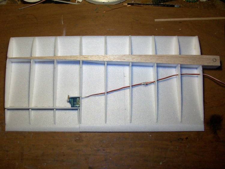
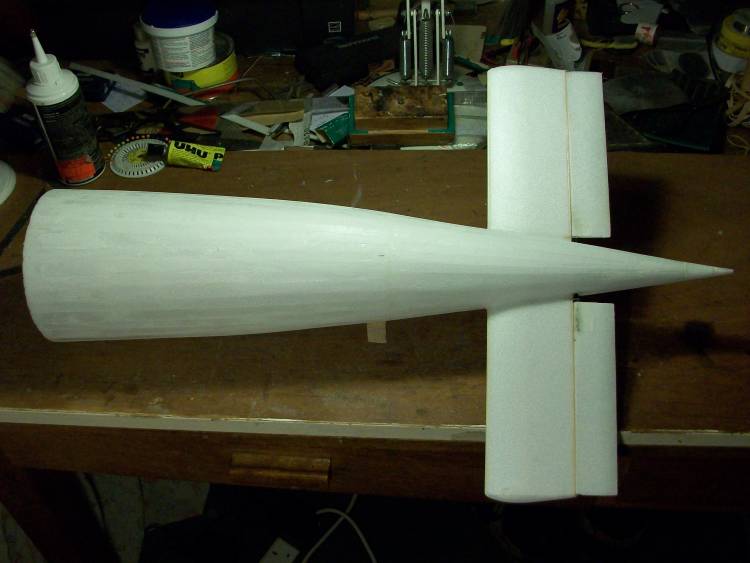
The wing has a substantial but tapered 'box' spar made up of thin balsa top and bottom flanges with 3 mm Depron sides.
LhAilServo.JPG

The small area ailerons allow a tiny and completely buried 3.7 g servo to be used.
Each wing half has a short spar root extension that plugs into a substantial hollow beam, built in the same fashion. that runs across the fuselage.
SparBoxA.JPG

The ability to get your hand into the fuselage made this operation much easier.
Ultimately the wing halves will be glued in place.
For strength and to save weight it will be a 'one piece' plane with I fear very limited crash resistance.;)
 

quorneng

Master member
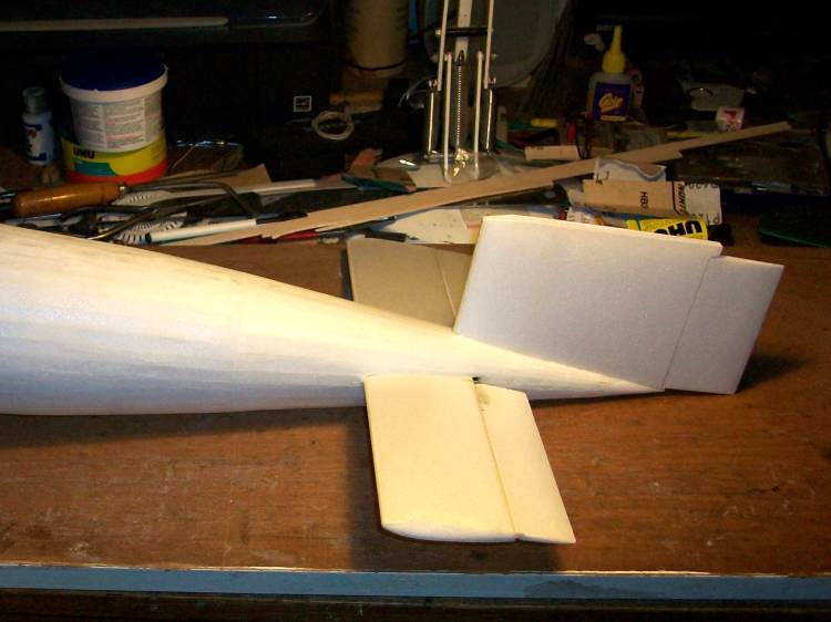
The two rear fuselage sections joined with the tail plane in place.
RearJoined.JPG

The halves of the elevator are joined by a section of glass fibre tube. The elevator will be operated by internal pull/pull wires about 36" long :eek: from a servo positioned in the nose. This will help to counter the weight of the EDF mounted so far behind the wing.
 

quorneng

Master member
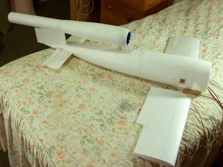
Its only when you come to mount the relatively heavy EDF that you realise the important role the front support and the fin play.
FinRudder.JPG

The rudder is purely 'decorative' and is fixed. If it flies at all it be 'bank and yank'.
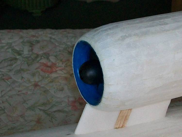
The front support carries the relatively heavy EDF so is treated as a 'wing' with a balsa spar.
InletEDF.JPG

That spar goes right across the fuselage.
Starting to look a bit more like a V-1.
3FuseJoin.JPG

As everything else will be in the nose there are lots of long wires, as well as a the elevator pull/pull lines.
 

quorneng

Master member
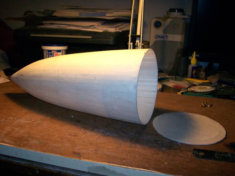
Finally the fuselage nose section. It was built vertically as before.
NoseCmplt.JPG

The idea is to stick it complete onto the front of the fuselage and then cut it open to give access to mount the battery, ESC and elevator servo.
CablesESC.JPG

Rather a severe operation but despite a big opening it still holds its shape.
The nose made good leaving a battery hatch just big enough to slide in the 1800 mAh 3s.
1800Battery.JPG

Done this way it meant the battery & box could be positioned to give a safe CofG at 28% wing chord.
If this proves to be nose heavy it will only take a tiny weight added to the end of the tail pipe (its 40" or 1010 mm behind the CofG!) to make a substantial difference.
Nearly there!
 

quorneng

Master member
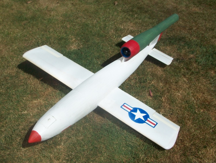
The completed JB2 "Loon" decorated in a scheme used for one at the White Sands testing grounds.
29May20.JPG

It weighs 595 g (21 oz) ready to go.
I then came across a problem. How to hold it for a hand launch?
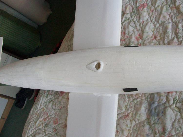
The fuselage is too big a diameter to grip firmly enough to give it any sort of throw so I added a reinforced finger hole on the under side.
FingerGrips.JPG

With fine grade sandpaper 'grips' on either side. So thumb and little finger either side, index finger in the hole to provide the 'impulse'.;)
With a wing area of 2.3 sq ft the wing loading is only 9.1 oz/sq ft which puts it at the upper end of the glider category! :D
It does fly - actually quite well.
 

Timmy

Legendary member
The completed JB2 "Loon" decorated in a scheme used for one at the White Sands testing grounds.
View attachment 177782
It weighs 595 g (21 oz) ready to go.
I then came across a problem. How to hold it for a hand launch?
The fuselage is too big a diameter to grip firmly enough to give it any sort of throw so I added a reinforced finger hole on the under side.
View attachment 177783
With fine grade sandpaper 'grips' on either side. So thumb and little finger either side, index finger in the hole to provide the 'impulse'.;)
With a wing area of 2.3 sq ft the wing loading is only 9.1 oz/sq ft which puts it at the upper end of the glider category! :D
It does fly - actually quite well.
looks weird but cool!