Sizing a foamboard airplane

Inq

Elite member
Please understand I'm not complaining. I just wonder what the thought process that drives a design. I'm just laid out the plans for an FT Mini Arrow. There is a whole lot of white space on the board. It seems to me that either the plane could be made just and inch or two shorter and could all fit on one sheet of foamboard. OR... it could be made a good deal bigger and still utilize only the two sheets it does now. I was wondering is there some "race" class that defines the dimensions this is meant to enter or is there some other aspect?

The couple of my own designs I've been playing with, I focus ether reducing the board count or maximizing the use of it.
 
Last edited:

Inq

Elite member
The question has nothing to do with expense... but why was that size picked? People usually make decisions based on some logic. Usually there is a driving dimension, goal or specification that must be met. By your logic we should put one piece on a fresh sheet and use twenty sheets and have 95% waste. I'm just trying to find out what was the driver here for my education into FT design methodology. It could have been made about 35% bigger and still fit on two sheets. It could have been make about 10% smaller and all would fit on one sheet. I'm just missing the logic of the size chosen on this plane.

236219
 

bisco

Elite member
i guessyou'd have to ask the designer, or model designers in general. i have no idea how they decide on size/weight/power
 

Tench745

Master member
A point worth noting; the plans are not formatted on a 20x30 sheet size. They're on a 34"x22" layout (some standard ANSI size). And the FT kits that are laser cut tend to hold-back from the edges of the foamboard so that damage to the edges of the sheet don't unnecessarily trash the cut parts.
No race classes or anything; just a lot of TLAR (That Looks About Right) engineering based on material size, motor selections, etc.
I believe the Arrow specifically was developed to be small enough to carry around on a backpack like other FPV quads were while still being large enough to carry the FPV equipment of the day and fly well.
I agree that even considering these factors, many of the FT designs are not optimized for minimal sheet usage. When I cut my planes I usually rearrange the pieces to get the most out of each sheet of foam.
 

SP0NZ

FT CAD Gremlin
Staff member
Admin
Moderator
Mentor
A point worth noting; the plans are not formatted on a 20x30 sheet size. They're on a 34"x22" layout (some standard ANSI size). And the FT kits that are laser cut tend to hold-back from the edges of the foamboard so that damage to the edges of the sheet don't unnecessarily trash the cut parts.
Plans are actually formatted for 30x20 sheets. The 34 x 22 sheet format is just to accommodate US print shops. All the part templates fit into the 30 x 20 area of the page. The tile are setup the same way, 7.5 x 10 tiles in a 4 x 2 array equal 30 x 20.
 

SP0NZ

FT CAD Gremlin
Staff member
Admin
Moderator
Mentor
The question has nothing to do with expense... but why was that size picked? People usually make decisions based on some logic. Usually there is a driving dimension, goal or specification that must be met. By your logic we should put one piece on a fresh sheet and use twenty sheets and have 95% waste. I'm just trying to find out what was the driver here for my education into FT design methodology. It could have been made about 35% bigger and still fit on two sheets. It could have been make about 10% smaller and all would fit on one sheet. I'm just missing the logic of the size chosen on this plane.

View attachment 236219

The plans are not optimized for yield per sheet of material. They are optimized for the people that build from plans to minimize the number of seams/tiles required per part.

As for how the size is determined, I suspect it has a little to do with the size of the raw materials, but a lot of other factors will come into play depending on the desired criteria for the model. I can't speak for any of the FT designs, but for some of mine, I have sized them for many different reasons. I don't think there is a one-size-fits-all rule that applies here (pun very much intended).
 

Inq

Elite member
I have sized them for many different reasons. I don't think there is a one-size-fits-all rule that applies here (pun very much intended).
:LOL: When I asked the question, I was sure your statement is correct. I can see that many of the FT designs are based on the 30" DTFB. They're ~14xx mm total. Just enough to account for any edge damage on the DTFB. Me... if the board isn't perfect in DT... it doesn't come home. I use the edges as a cut line.

I agree that even considering these factors, many of the FT designs are not optimized for minimal sheet usage. When I cut my planes I usually rearrange the pieces to get the most out of each sheet of foam.

It may be tough to see, one wing is already cut out, but I only print and cut out one wing template. And again... its an efficiency thing... not a penny pinching thing.
236236


I also can imagine that for Flight Test selling kits, they have a different set of criteria. They want to make sure that any slight shipping damage doesn't result in a customer having a bent corner that is in a part. And that makes sense for all of their planes I've looked at. Then there is this one, that I failed to rationalize a reason.

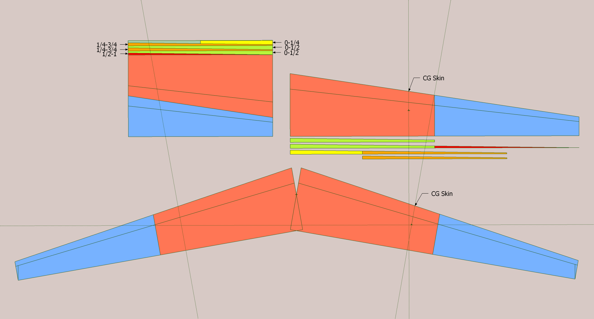
With critical placement, even this design can almost fit on one sheet. The little red portions are on the lower skin and not even visible. I don't know what affect they'd have on the flying characteristics if they were missing. If you are making one with the center pod by "REMOVE FOR OPTIONAL ELECTRONICS POD" you could squeeze the pieces together and get them fully on one sheet. The only thing missing is the spar. If you've even built one other plane you probably have enough foam board in a bin to fit the spare on... this becomes a one board plane with no size adjustment.

The point I'm reaching for wasn't so much trying cram this into one sheet, but why they didn't upscale the plane and use more of the two sheets. And...

No race classes or anything; just a lot of TLAR (That Looks About Right) engineering based on material size, motor selections, etc.
I believe the Arrow specifically was developed to be small enough to carry around on a backpack like other FPV quads were while still being large enough to carry the FPV equipment of the day and fly well.

... makes a lot of sense. Re-watching Josh's video, he mentioned racing. And I know those are usually very well defined what you can and can't do. I was suspecting that it was a race class hard specification.
 

Inq

Elite member
Almost 100% board utilization. Not because of saving money, but to build the biggest glider possible. 2 DTFB, 3 meter wingspan.
434737_aa8aa93d87532cfdb4a8331a25221ecd.png
 

SP0NZ

FT CAD Gremlin
Staff member
Admin
Moderator
Mentor
I was wondering is there some "race" class that defines the dimensions this is meant to enter or is there some other aspect?

I believe that the FT Mini Arrow (2016) pre-dates some of the FPV spec wing designs that have come along since. I while back I did some plans for the FPVWRA foam board spec wing. I'm not sure if the FPVWRA is still active or not, but I think you can get the plans from there website.
 

Foamforce

Well-known member
@Inq, this is the design you’re looking for. 😂

The OSG (one sheet glider).

But seriously, I do intend to build this eventually. It looks like a seriously good flyer.

Fwiw, I’ve definitely seen a few designs that could have been rearranged to use one fewer sheet. A lot of people who scratch build cut the pieces out of the printout and arrange those on the foam boards to optimize. I don’t though. I use a kids glue stick to tack the printout to the foam board and cut through it. That means I have more foam waste. It bothers me a little, but not enough to change my method.