L Edge
Master member
After looking at kilroy07 build thread that he was doing, it got me interested in doing my version of the SR-71. But what interested me was "what happens with inlet ducting and what is going to happen if a nose cone shaped like the SR-71 is added.
My design was to scale it with flat foam and use my cheap $10 "5 bladed 64mm fans at 3S" loaded with a 3300mah battery.


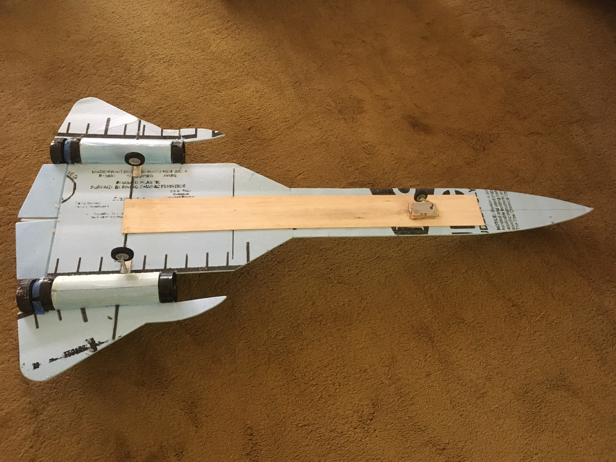
Overall dimensions are approximately 32" wide and 61" long. You will notice fans are placed so that I can add inlet ducts and nose cones in the future to see what info can be deducted. Notice that the main gear is placed over the carbon fiber rod and stearable nose gear by a servo. Since the heavy battery is place in forward area, ended up using a balsa plank(heated and then hot glued to foam) to strengthen the nose and yet be light in weight. Re-inforced neck with a second strip so it strengthen the nose and allowed me to hold for the launch. These pics were taken after flight and wrinkles were caused by the landing gear grabbing in the unmowed high grass.
CG was found by throwing it into a good strong wind and moving the battery.
"Covid" closed our paved runway at the field and it sat around in the cellar. So decided to go for it by just chucking it at the soccer field and see what happens. By watching videos like the XB-70 (pieliker96) and others, knew I needed a lot of space to fly this one and know that turns have to be wide and gentle due to the long nose.
Added these features to help flight control.
1) Made large control surfaces for roll and pitch. Used 30% expo.
2) I have gymbal 2 dimensional ball valves for fan exhaust and to give better stability for the nose.
3) For yaw, differential thrust came from using a "V-Tail mixer hooke to the fans. Why that? -- requires throttle and rudder channels only, no programming needed, and best of all, the throttle and rudder trims adjust the fans so that they start together and can be synced together while flying.
Flight didn't last long due to a small field and still a slight aft CG, so after I resolve the CG issue, will try the inlet ducts and nose cone.
[/MEDIA]
My design was to scale it with flat foam and use my cheap $10 "5 bladed 64mm fans at 3S" loaded with a 3300mah battery.


Overall dimensions are approximately 32" wide and 61" long. You will notice fans are placed so that I can add inlet ducts and nose cones in the future to see what info can be deducted. Notice that the main gear is placed over the carbon fiber rod and stearable nose gear by a servo. Since the heavy battery is place in forward area, ended up using a balsa plank(heated and then hot glued to foam) to strengthen the nose and yet be light in weight. Re-inforced neck with a second strip so it strengthen the nose and allowed me to hold for the launch. These pics were taken after flight and wrinkles were caused by the landing gear grabbing in the unmowed high grass.
CG was found by throwing it into a good strong wind and moving the battery.
"Covid" closed our paved runway at the field and it sat around in the cellar. So decided to go for it by just chucking it at the soccer field and see what happens. By watching videos like the XB-70 (pieliker96) and others, knew I needed a lot of space to fly this one and know that turns have to be wide and gentle due to the long nose.
Added these features to help flight control.
1) Made large control surfaces for roll and pitch. Used 30% expo.
2) I have gymbal 2 dimensional ball valves for fan exhaust and to give better stability for the nose.
3) For yaw, differential thrust came from using a "V-Tail mixer hooke to the fans. Why that? -- requires throttle and rudder channels only, no programming needed, and best of all, the throttle and rudder trims adjust the fans so that they start together and can be synced together while flying.
Flight didn't last long due to a small field and still a slight aft CG, so after I resolve the CG issue, will try the inlet ducts and nose cone.
[/MEDIA]
Last edited:
