Tough Tilt Tricopters!

fliteadmin

Administrator
Staff member
Admin
Moderator

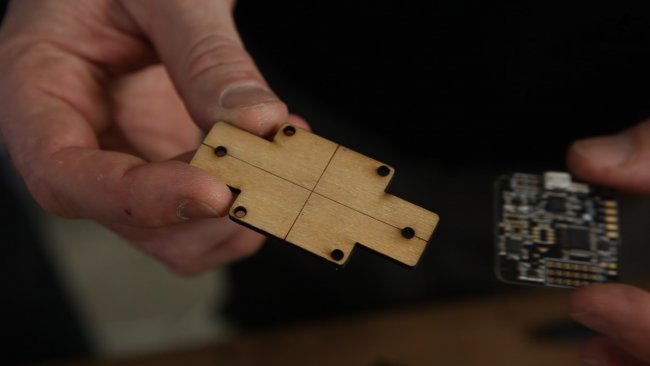
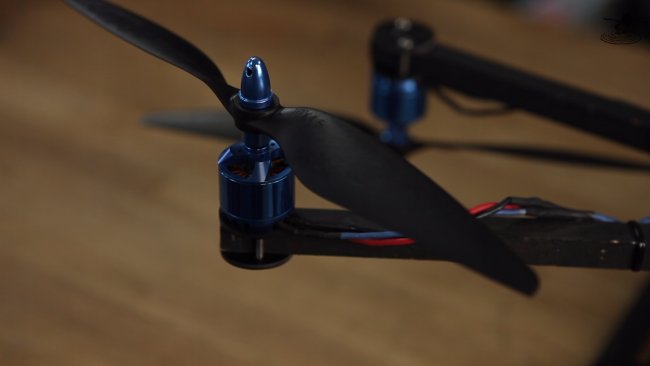
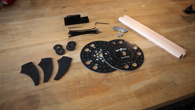
Introducing the Flite Test Tough Tilt! A rear motor mount system for your yaw-controlled mutli-rotor!


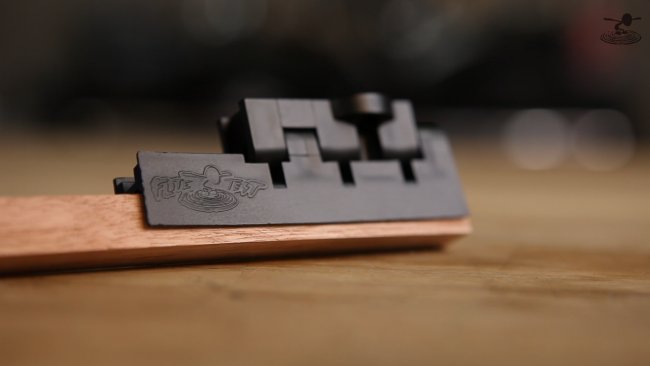
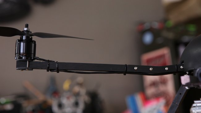
We listened to multi rotor pilots and read the feedback and we’ve answered your requests with the Tough Tilt, by delivering a durable, low-profile motor mount option that is designed around the ElectroHub and other Rotor Bone components!


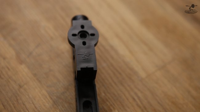
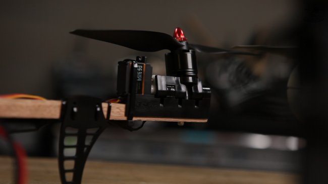
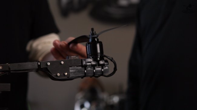
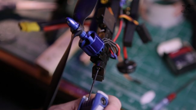
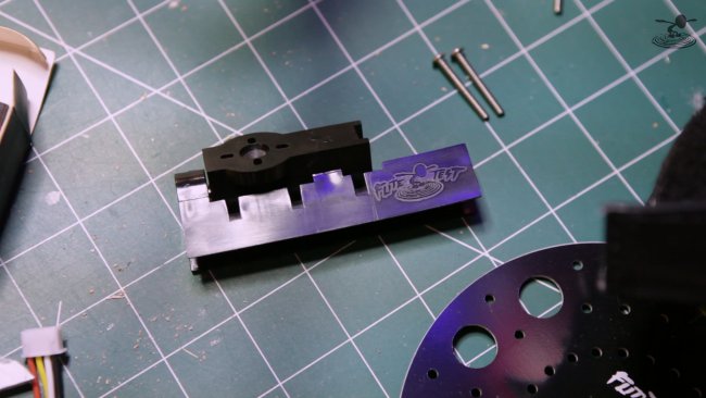
Although our ElectroHub has been around for awhile, the Tough Tilt tail/yaw mechanism is brand new.


ft-tough-tilt-edit-00-03-02-00-still007-png_1425422456.jpg


Unlike tradition homemade or 3D printed designs, the Flite Test Tough Tilt is injection molded, durable plastic yaw mechanism built to last.


ft-tough-tilt-edit-00-01-55-18-still004-png_1425425337.jpg


We've learned a lot over the years and we've been listening to what multirotor pilots were telling us.


mvi-9981-mov-00-01-23-04-still002-png_1425422382.jpg


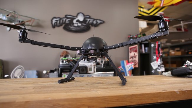
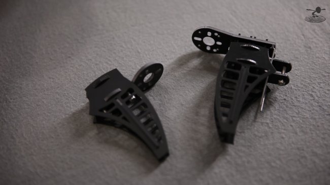
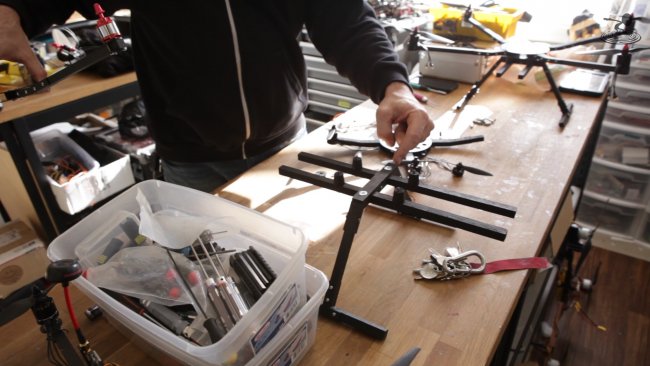
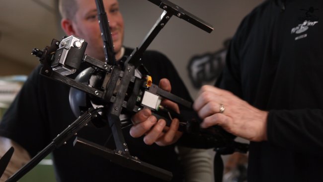
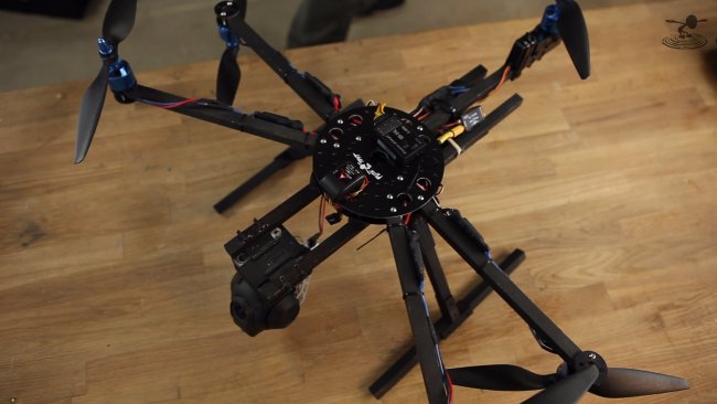
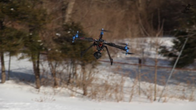
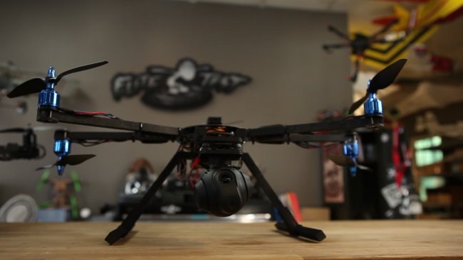
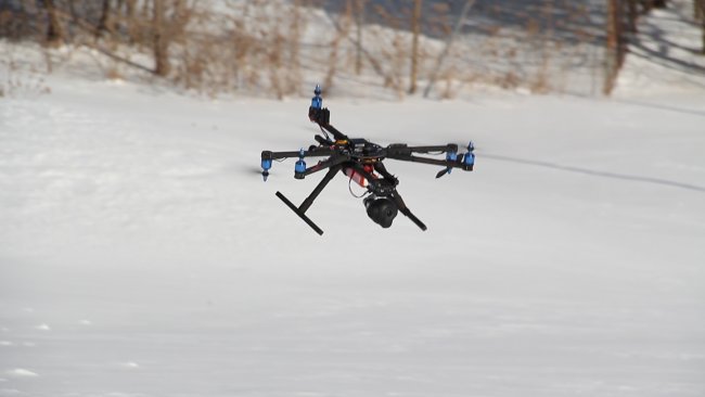
Eric’s Tricopter is built around the ElectroHub and is currently a test-bed for some new and upcoming Flite Test products.

ft-tough-tilt-edit-00-12-14-06-still030-png_1425422429.jpg


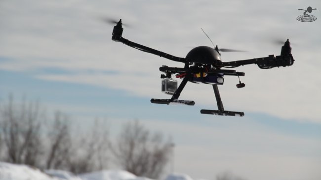
His multicopter features Angle Arm Brackets and a Flight Control Board Plate (available in our Online Store) Eric’s setup also features a prototype landing gear mount as well as a prototype camera/gimbal and battery mounting adapter.


ft-tough-tilt-edit-00-07-26-03-still013-png_1425425326.jpg


Let us know if you’d like to know more about some of these prototype designs and ElectroHub add-ons. Be sure to check out the Online Store for some items that may already be available!


ft-tough-tilt-edit-00-10-31-08-still031-png_1425422316.jpg


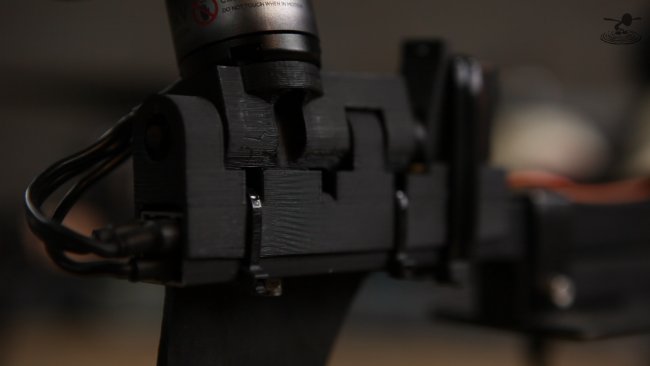
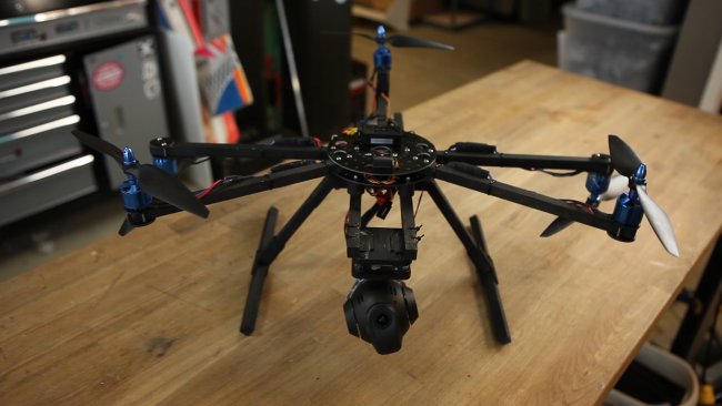
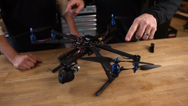
Eric is also working on a ‘drop-down’ design that places the rear motor at the same height as the other two motors, keeping everything "symmetrical".
ft-tough-tilt-edit-00-15-29-22-still020-png_1425422780.jpg


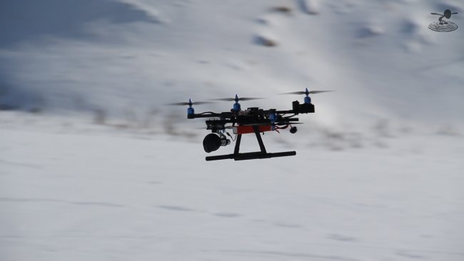
Balance is an important thing when building a multi-rotor built for AP, aerobatics and optimal flying experience.


ft-tough-tilt-edit-00-08-55-08-still014-png_1425425209.jpg


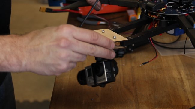
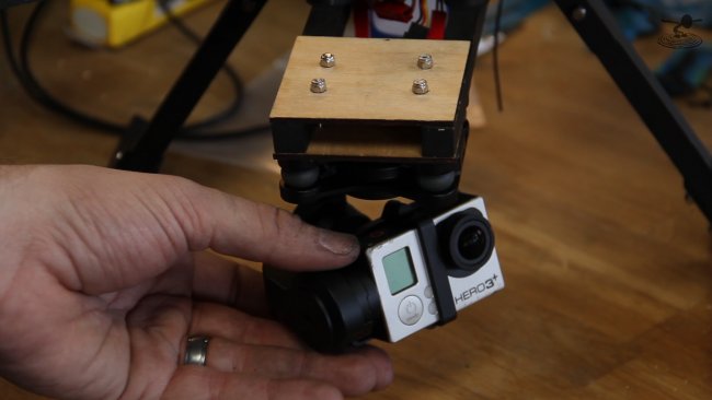
With the ability to shift CG with camera mounts and battery, the landing gear/ camera platform builds seamlessly onto the ElectroHub opens up all kinds of cargo carrying options on your multi rotor.


ft-tough-tilt-edit-00-15-13-11-still032-png_1425422377.jpg


ft-tough-tilt-edit-00-15-20-23-still019-png_1425422806.jpg


ft-tough-tilt-edit-00-15-36-22-still033-png_1425422335.jpg


mvi-0016-mov-00-01-43-09-still001-png_1425425910.jpg


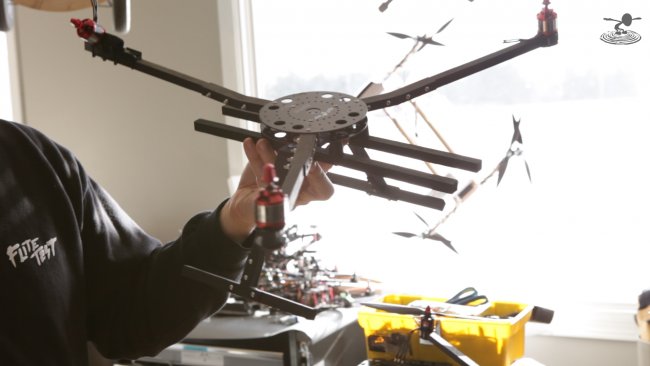
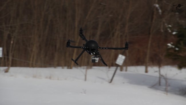
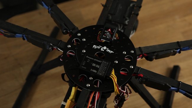
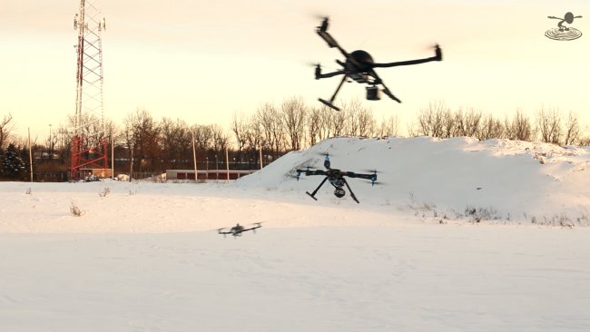
All of the “tricopters” (multi rotors) are designed around the Flite Test ElectroHub and the new Tough Tilt tail servo mount.


ft-tough-tilt-edit-00-09-30-12-still012-png_1425425237.jpg


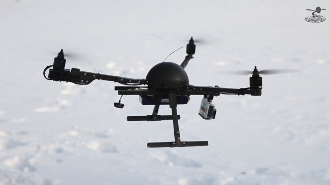
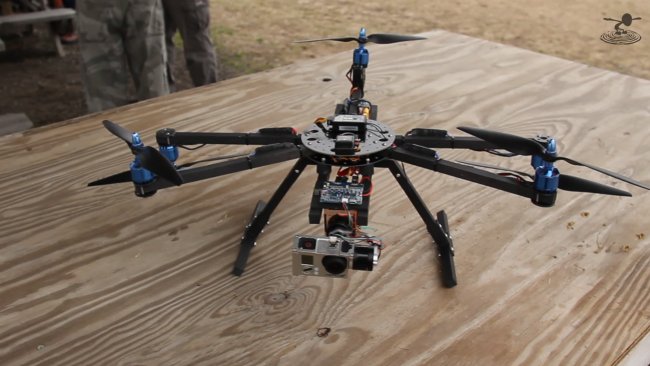
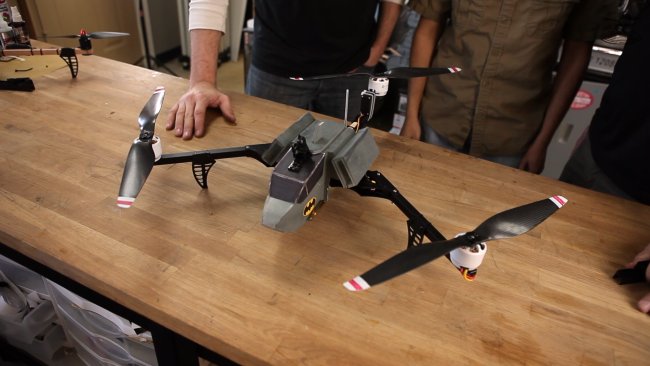
Josh’s “tricopter” err.. Pentacopter is designed as an AP (aerial photography) ship but is also setup with additional arms/ motors for redundancy and power while flying with a gimbal or camera system.
mvi-0009-mov-00-00-18-00-still001-png_1425425208.jpg


ft-tough-tilt-edit-00-13-36-18-still018-png_1425422837.jpg


This design is available as a kit that we call The Dragonfly. This pentacopter is built around the ElectroHub utilizing our prototype camera mount landing gear as well as the usual 13mm wooden booms common with all of our multi rotor kits.


mvi-0010-mov-00-00-28-01-still001-png_1425425132.jpg


ft-tough-tilt-edit-00-13-45-01-still017-png_1425422873.jpg


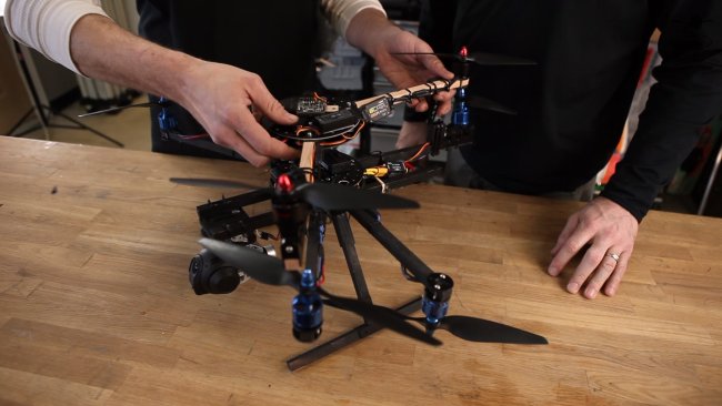
The Dragonfly is Josh’s answer to the Inspire 1 from DJI. He’s cheap and wanted to create a multi rotor that could still be stable and offer a good platform for his gimbal system.
mvi-0011-mov-00-00-07-19-still001-png_1425427255.jpg


Which in this case, is a custom painted C-Go2 GB300 HD Camera/ 3-Axis Brushless Gimbal from our Blade QX3


ft-tough-tilt-edit-00-17-48-08-still023-png_1425422713.jpg


ft-tough-tilt-edit-00-17-33-18-still022-png_1425422636.jpg


ft-tough-tilt-edit-00-15-44-05-still034-png_1425422219.jpg


mvi-0718-mov-00-02-52-00-still001-png_1425425855.jpg


ft-tough-tilt-edit-00-18-57-06-still026-png_1425422644.jpg


Peter’s multi rotor is built on the BatBone and features a custom foam board canopy.
ft-tough-tilt-edit-00-20-07-14-still028-png_1425422486.jpg


Peter's tricopter is built on the BatBone kit frame, with Simple Delrin Landing Gear and Simple Motor Mount Discs.

ft-tough-tilt-edit-00-19-25-17-still027-png_1425422514.jpg


ft-tough-tilt-edit-00-19-10-21-still025-png_1425422671.jpg


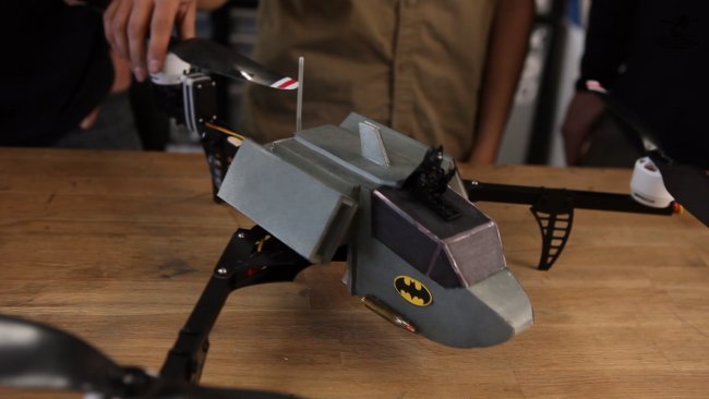
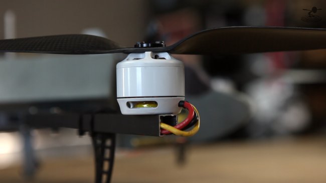
Peter customized his tricopter with HUGE Avroto LIFT 3515 400Kv motors (the same motors used on the Heli Carrier) swinging 15 x 5 props with custom painted tips.


ft-tough-tilt-edit-00-02-24-22-still006-png_1425425301.jpg


We’ve been building and testing over the past year and we’re happy with the end results in our Tough Tilt design. After putting it through it’s paces, we’re confident in it’s construction. So much so that we are offering a 2 yr warrenty on the Tough Tilt (not the servo).


ft-tough-tilt-edit-00-02-15-23-still005-png_1425425419.jpg


If for any reason you break or damage your tough tilt within 2 years of purchasing, mail it back and we’ll replace it for free! Be sure to send us a photo of the crash that cause the wreck, we’re sure it will have to be epic to have caused a broken Tough Tilt.


The Tough Tilt is available now! Be sure to take a look at some of the other great multi-rotor components in the store! Let us know what else you'd like to see!


Check out the web store for our full line of multi-rotor kits and components!


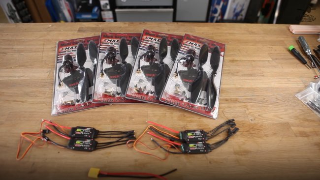
We also have complete Electronic Packs available in our store! CLICK HERE to learn more!


ft-tough-tilt-edit-00-25-27-10-still035-png_1425425896.jpg


All of these designs were created to give you just an idea of all of the options available when designing around the Flite Test Electohub Rotor Bones components. We're excited to offer the new Tough Tilt and to see what kind of multi rotor designs you come up with!
Thanks again for all of your input and support!
 

dlsspy

New member
I noticed this is for 1/2" booms. Are there any thoughts about creating one that supports 10mm booms? David's current tricopter offering uses 10mm carbon fiber booms. Should I break the tail mount again, this would be a nice replacement (except for the part where it doesn't fit).
 

DharanFlyer

Active member
Awww! Just ordered a Naze32 from HobbyKing. Would of gotten from you if there was just a few days difference one way or the other! Next time.
 

PHugger

Church Meal Expert
10mm wood booms would likely not be strong enough.
CF booms are certainly more costly.
FT is all about cheap,,,,,,,

That said - I don't know if the FT frames can accommodate different sized booms.
Perhaps someone who has one can speak to this.


Best regards,
PCH
 

makattack

Winter is coming
Moderator
Mentor
Looks like with Erics modified tail mount that lowers the tilt, you may be able to jury rig it to fit 10mm CF booms...
 

Balu

Lurker
Staff member
Admin
Moderator
I don't want to take the fun away from Peter and I understand that the general view on guns is a lot more relaxed in the US than in other parts of the world, but I'm not sure about the "family orientation" with the gun enthusiasts website Peter's builds quite often promote or the rounds attached to the "batman copter" this time.

PS: Quite a few Youtube commenters seem to like that though.
 
Last edited:

D. R. Bowers

Junior Member
Angle arm bracket placement.

Do you think that the angle arm brackets be used further out on the arms just beyond the prop arc. I think that it would keep the motors lower.

Thanks.
D. R. Bowers
 

CrashTestPlanes

Junior Member
Can anyone found the patent they are talking about? I can only find patents where a servo spline is part of the design, such as http://www.google.nl/patents/US8324773. Almost all of them seem to be from ServoCity.
To me it doesn't look like there is a patent on putting a spline in something, rather the completed item itself. Why on earth would futaba or any other manufacturer want to stop people using their servos in their designs?

I personally see this as a clever attempt to discredit RCExplorers tilt design. It seems near impossible to find any proof that putting splines in something is under patent, and most people don't understand how patent law works. Many people immediately associate this with the horror stories of small companies being sued buy large corporations because of some obscure patent.
FliteTest has high credibility with many of it's viewers. Most people will believe you when you say that David is being illegal when selling and distributing his design, when there is 0 proof of that.

It's a very clever business move. Thanking the same person which you then try and discredit in the same video. Very clever and frankly quite maleficent.
I figure David is the biggest "threat" when it comes to the tricopter market, but accusing someone of breaking patents without proof is slandering and in my opinion far from what I expected from FliteTest and Josh Bixler.
It seems lite FliteTest is walking down the path of doing whatever it takes to sell more products.

On the note of 3D printed tilt mechanisms being weak and easy to break. Sure if you don't know how to 3D print properly and don't design the tilt for 3D printing specifically, I can imagine that being a problem. Printing at the correct temperature and having a good amount of surface contact between each layer will make all the difference in the world. The only 3D printer I've seen you guys use is the Afinia H series, printing ABS, that sits next to a huge drafty window. Not the best combination when trying to get layer adhesion.

Have you even tried Davids design?
It's ridiculously strong and light weight. But it is designed to break before killing the servo. I personally rather replace a tilt piece than destroying a servo. Especially as tricopters flies so much better with a nicer tail servo, which tend to be more expensive than the not so very good $12 emax servo that's recommended.

I'm very disappointed in FliteTest. Bashing another persons product without trying it and saying they are doing something illegal when they are not. Surely David can't be that big of a threat? Or is is something personal Josh?
 

CrashRecovery

I'm a care bear...Really?
Mentor
Crashtest I'm not sure I understand how they are bashing a product. They have been prototyping this design for a while. Unless you step up to the more expensive material for 3d printing you are going to have failures. They were not bashing David's design. If you do some research they were using his original design for a long time. Also if I saw correctly even David was having issues with his new design failing. 3d printing has it's good and bad.
It comes down to personal preference. Josh and David have no I'll blood between them. David was a big part of why ft is where it is today. David has the ability to do things we can't in the usa because of rules and regulations. Give the guys some slack and I guarantee they will impress you
 

Kurt0326

Your ADD Care Bear
Mentor
I have a question. Who's going to build a tough tilt racing H quad? Where the motors tilt forward to reduce drag. I don't have the money, but I'm sure there's someone with money burning in their pockets...:p
 

AdamBomb42x

New member
I'd like to know how the "Dragonfly" performs acrobatically. When I think of how it works in my head, I surmise that when attempting a backflip it would be slow and want to climb, which would be bad as once it goes vertical and beyond it would lose a lot of altitude. I think this because the two added motors would be thrusting up while the front motors are trying to pitch.

I would sure like to see someone take on configuring a FC to see and properly work with all five motors.

Am I incorrect in my assumption or does anyone concur with what I'm saying?
 

jason51873

New member
Any tips on how I could mount the Tough Tilt to a round carbon tube? Looks like its really only made for square stock.
 

Craftydan

Hostage Taker of Quads
Staff member
Moderator
Mentor
The old-school approach is to create a mounting block using the boom, a piece of sandpaper, and a block a bit wider than 1/2 the booms thickness.

Bend the sandpaper around the boom, and use the bent section on the wood block to cut a matching semicircular groove down the block's length. Typically these are either bolted or glued onto the boom -- if you just use only zipties, it'll likely twist on the boom. You could build one top and bottom, glue the bottom one, zip tie the top on to it and let the top one break free in a crash . . . assuming the boom doesn't crack as well.
 

Trinitron79

Senior Member
Question on their build.

They mention that a Tri can run all "conventional" props, does that mean Clockwise? Looking at the Naze32 manual it looks like all the props are running Counter Clockwise (Anti Clockwise).

http://www.abusemark.com/downloads/naze32_rev3.pdf

However during the build video they make mention that you can use a reversing prop configuration. (43:30 mark) Could someone confirm / debunk this?

Tri-Config.png
 

CrashRecovery

I'm a care bear...Really?
Mentor
Not in the naze but other boards allow you to run the props in all the same direction. Mostly turning to the right if you are looking down at the motor
 

devindied

SEL MEL CFI CFII MEI
Conventional is counter-clockwise. However, this can be argued as it's all about perspective. From a top view, conventional is counter clockwise. From the pilots seat( motor in front, normal plane) it rotates clockwise. From what I gather(I have ordered the tri and naze32, waiting fulfillment) you can run all motors conventional with normal props. This hurts efficiency as you have more torque to deal with in the tail motor, requiring a more aggressive tilt, thus hurting efficiency. Running clockwise and counter-clockwise seems to be the best option. However, it requires reverse rotation propellers.