jim_patrick
New member
Hey Everyone,
I've been working on a project over lockdown and thought I would share it with you all, hopefully it will be of interest to a few!
I've been tinkering with Arudino boards now for a few years and one project I wanted to try was the balancing robot. This looked cool but I thought 'hmmm how can I make this more interesting..?' So I was wondering if it could balance in 2 axes rather than just the 1, and I love things that fly so making a flying balancing robot seemed like the next obvious step.
I figured I'd need 2 motors, ideally contra-rotating that can be gimballed, a bit like a rocket, and that should be enough to give me full control. I designed the whole thing around a pair of motors I found online, contra-rotating motors aren't too popular these days but I found just the right one which allowed me to size the rest of the vehicle around it.
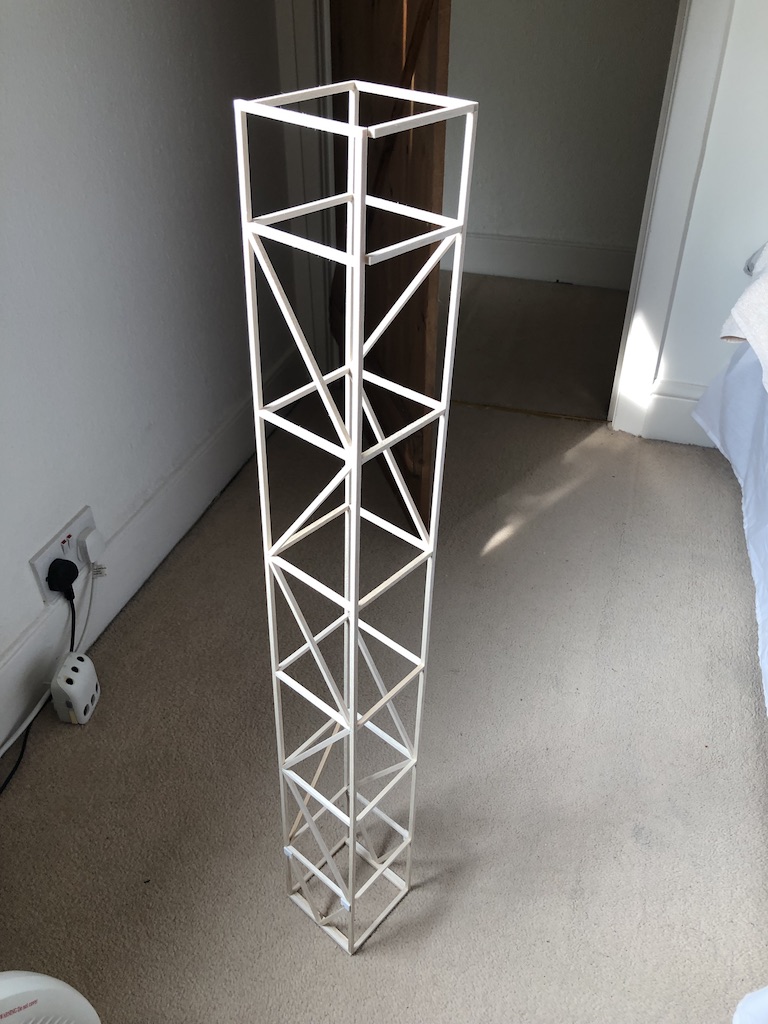
The frame is just 5mm (3/16") balsa square 900mm long. I thought I had made a mistake using this when I felt the balsa as it was like spaghetti! But once the truss structure was complete it was very rigid.

I never actually weighed the frame (annoyingly) but from weighing some end cuts I had lying around and measuring how much of the stuff I used I think the frame came in around 60g. It is very stiff, but in a crash it doesn't fair too well.
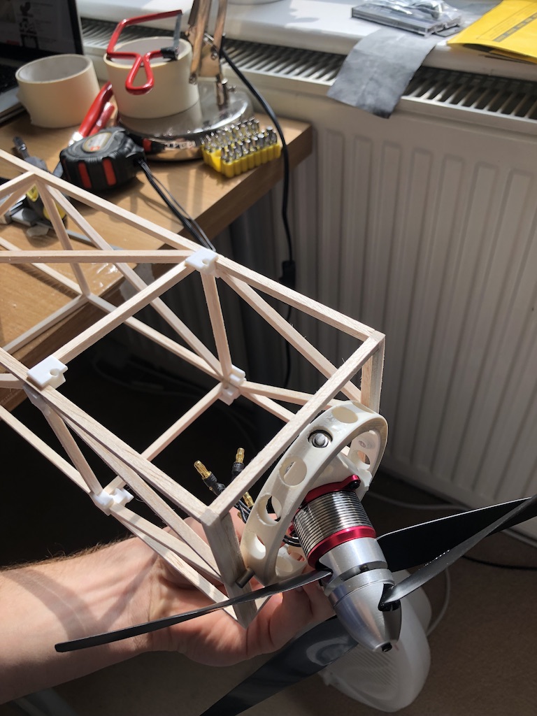
This is the contra-rotating motor that I got from that well known online auction site. It was about £50 and has been great so far. It has two 9x5 props and makes a hell of a racket when it gets going. The gimbal was designed in CAD and sent off to get 3D printed as I don't have one myself.

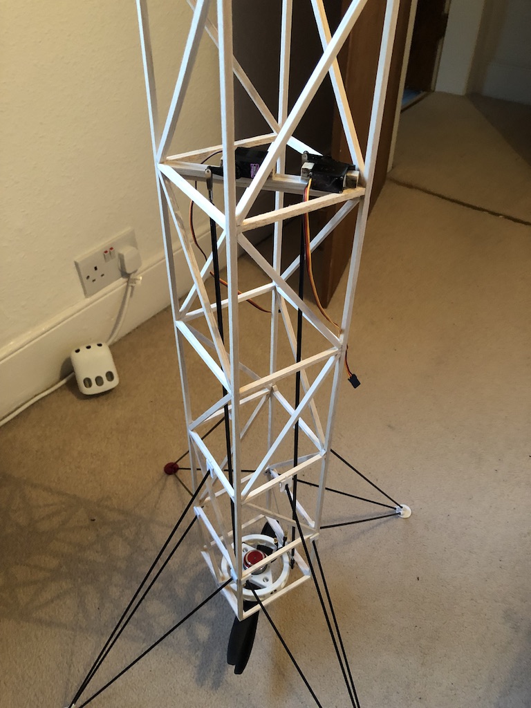
This photo above shows the 9g metal gear servos that actuate the thrust vectoring using 4mm carbon tubes as push rods. The landing gear is made from 3mm carbon tube. One issue I had early on is that the landing legs and frame are so stiff, the slightest hard landing would shatter the balsa frame. I got around this by (being a bit more careful! and) adding a spring to each of the central tubes on each side to absorb some of the landing shock. It works much better now but it could do with being stronger. It is very light weight which is good though.

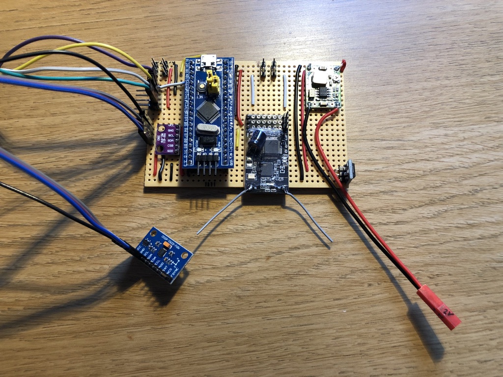
This is the flight controller which took the longest to complete by FAR. I coded the whole thing myself. I'll try not to go into too much detail here but if people would like more information on it I'll be happy to talk about it and share the code.
Processor is a STM32 (72MHz) programmed using Arduino IDE.
5v & 3.3v voltage regulators.
BMP280 barometer
MPU6050 IMU
8ch RC Rx. (PPM output)

At the moment it flies using a DX8, I'm in the process of integrating GPS into it so it can fly autonomously but for now it is radio controlled and stabilised.
The stick inputs for translation dictate the pitch & roll setpoints. So right stick neutral means the vehicle should be at 0degs & 0degs. If you move the stick hard over to the right, you are commanding 0degs pitch and 4degs rolls. The vehicle will rolls to 4 degress and stay there, this will then mean it will start to fly in that direction. Throttle is just simply throttle, and the yaw works but speeding 1 motor up and slowing 1 motor down.
In a nutshell the controller gets data from the IMU at 500Hz, it performs some calculations then computes the Pitch & Roll angles. (Upright is 0 degrees & 0 degrees). In another loop at 50Hz the controller looks at the difference between the actual vehicle angle and the desired angle. In control theory this is known as the 'error'. Based on the past, present & future error (PID control) the controller will actuate the thrust vectoring to achieve the desired body angle. The controller only updates the servos and ESCs at 50Hz as that is their maximum update rate so no point in going faster.
Yes I appreciate I could have bought a flight controller that would be good to go out of the box, but where's the fun in that!
- Flying video
I've been working on a project over lockdown and thought I would share it with you all, hopefully it will be of interest to a few!
I've been tinkering with Arudino boards now for a few years and one project I wanted to try was the balancing robot. This looked cool but I thought 'hmmm how can I make this more interesting..?' So I was wondering if it could balance in 2 axes rather than just the 1, and I love things that fly so making a flying balancing robot seemed like the next obvious step.
I figured I'd need 2 motors, ideally contra-rotating that can be gimballed, a bit like a rocket, and that should be enough to give me full control. I designed the whole thing around a pair of motors I found online, contra-rotating motors aren't too popular these days but I found just the right one which allowed me to size the rest of the vehicle around it.
The frame is just 5mm (3/16") balsa square 900mm long. I thought I had made a mistake using this when I felt the balsa as it was like spaghetti! But once the truss structure was complete it was very rigid.

I never actually weighed the frame (annoyingly) but from weighing some end cuts I had lying around and measuring how much of the stuff I used I think the frame came in around 60g. It is very stiff, but in a crash it doesn't fair too well.
This is the contra-rotating motor that I got from that well known online auction site. It was about £50 and has been great so far. It has two 9x5 props and makes a hell of a racket when it gets going. The gimbal was designed in CAD and sent off to get 3D printed as I don't have one myself.

This photo above shows the 9g metal gear servos that actuate the thrust vectoring using 4mm carbon tubes as push rods. The landing gear is made from 3mm carbon tube. One issue I had early on is that the landing legs and frame are so stiff, the slightest hard landing would shatter the balsa frame. I got around this by (being a bit more careful! and) adding a spring to each of the central tubes on each side to absorb some of the landing shock. It works much better now but it could do with being stronger. It is very light weight which is good though.

This is the flight controller which took the longest to complete by FAR. I coded the whole thing myself. I'll try not to go into too much detail here but if people would like more information on it I'll be happy to talk about it and share the code.
Processor is a STM32 (72MHz) programmed using Arduino IDE.
5v & 3.3v voltage regulators.
BMP280 barometer
MPU6050 IMU
8ch RC Rx. (PPM output)

At the moment it flies using a DX8, I'm in the process of integrating GPS into it so it can fly autonomously but for now it is radio controlled and stabilised.
The stick inputs for translation dictate the pitch & roll setpoints. So right stick neutral means the vehicle should be at 0degs & 0degs. If you move the stick hard over to the right, you are commanding 0degs pitch and 4degs rolls. The vehicle will rolls to 4 degress and stay there, this will then mean it will start to fly in that direction. Throttle is just simply throttle, and the yaw works but speeding 1 motor up and slowing 1 motor down.
In a nutshell the controller gets data from the IMU at 500Hz, it performs some calculations then computes the Pitch & Roll angles. (Upright is 0 degrees & 0 degrees). In another loop at 50Hz the controller looks at the difference between the actual vehicle angle and the desired angle. In control theory this is known as the 'error'. Based on the past, present & future error (PID control) the controller will actuate the thrust vectoring to achieve the desired body angle. The controller only updates the servos and ESCs at 50Hz as that is their maximum update rate so no point in going faster.
Yes I appreciate I could have bought a flight controller that would be good to go out of the box, but where's the fun in that!


