Cutting foam sheets... with a needle!

dkj4linux

Elite member
Thanks, Mark. I've just created a thread over on the MPCNC/LowRider site, if you want to take a look...

https://www.v1engineering.com/forum/topic/lowrider-inspired-foam-ripper/

Yeah, I was having difficulty plotting the crown with a pen simply strapped to the pen-mount you provided... that's why I thought I might need the Hicwic adapter. But then I realized I could simply meld a round post to Allted's pen holder, using Tinkercad, and then cable-tie it in place of the pen. Worked like a champ!

If you want them, I'll provide any STLs for the parts (not in your Thingiverse thing files) that I used to get all the wheel bearing and idler spacings/clearances for my build. I'll also be happy to provide any/all information as to what I did to get mine built and running. I tried to stay true to your design as best I could... but folks who try to build it right now, from your article and Thingiverse page as I did, are going to have a lot of questions without a bit more in the way of assembly instructions and required small parts.

Again, thanks for such a fun build! -- David
 

dkj4linux

Elite member
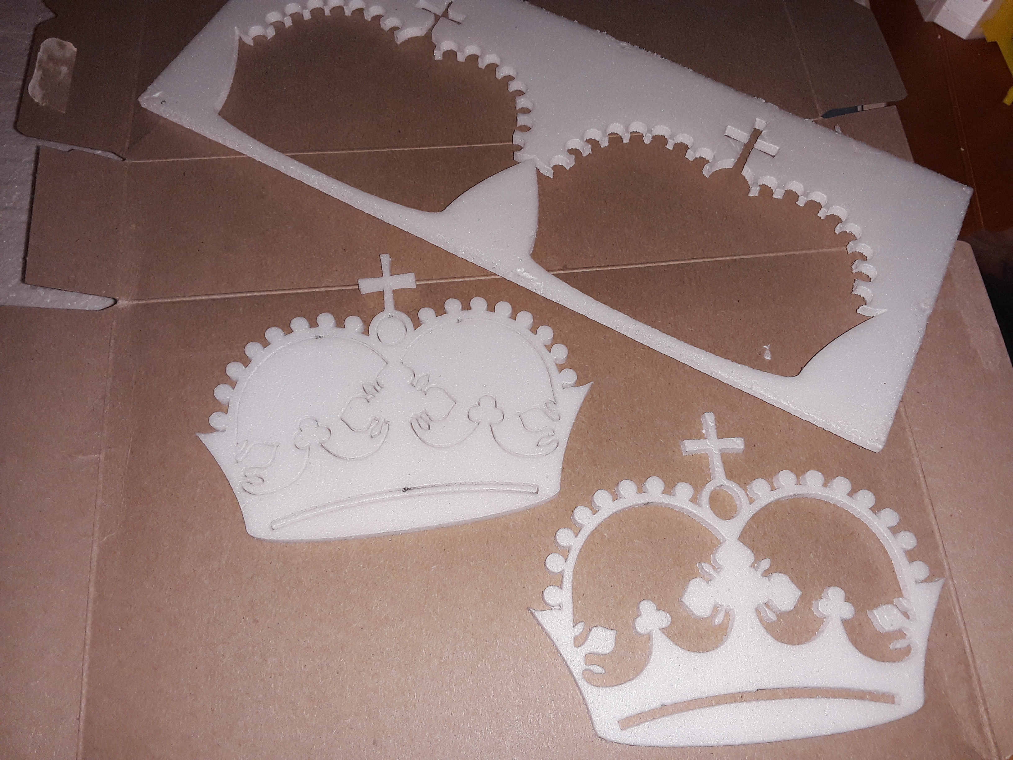
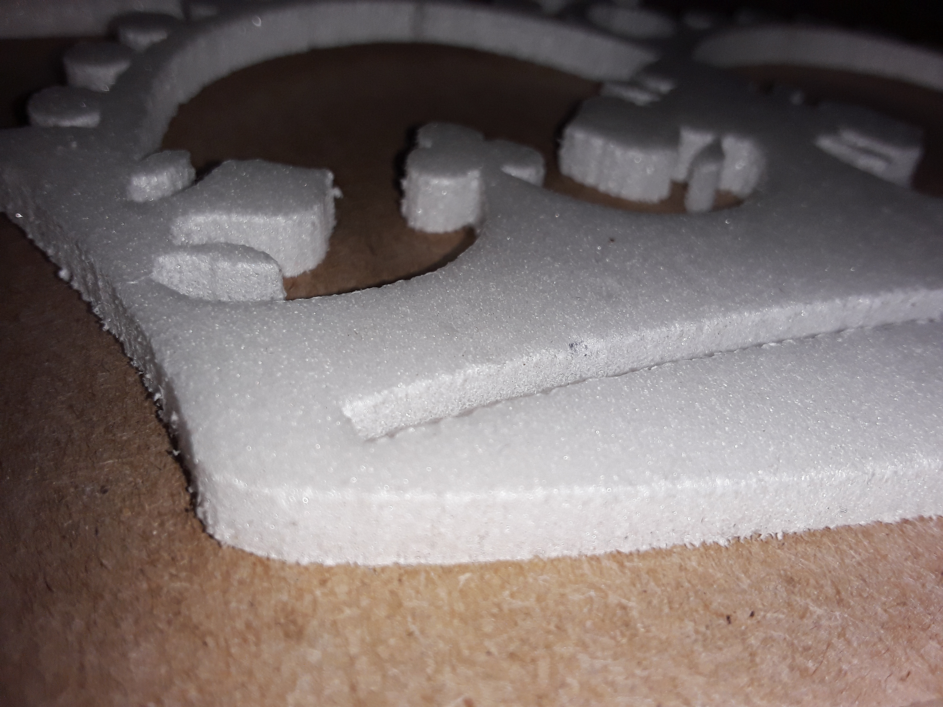
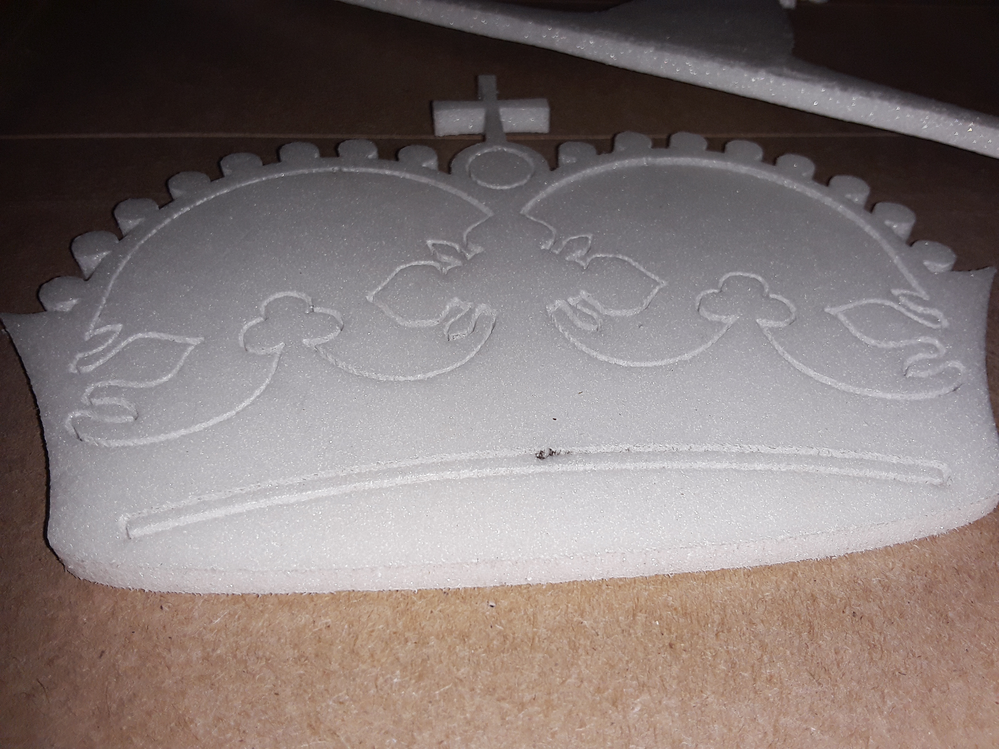
I decided, when I found a small scrap of foam (DTFB w/o paper), that I could start playing with the needle cutter and give a quick demo. These were the very first ever cuts with this particular needle cutter. The needle is a little long yet but the results are still reasonable, with a lot of small detail...

20180901_223735.jpg


20180901_223526.jpg


20180901_223751.jpg


20180901_223806.jpg


I made a video but it is uploading now... will post later.

-- David
 

TEAJR66

Flite is good
Mentor
That is great David! Thanks for sharing your build experience. That was a good idea for the spring on the pen holder.

Tommy, I could probably figure out how to share my Fusion360 files with you to make them easier to play with. They are a big mess because I was learning as I went. I was working on a Z axis piece that was more compact, but ran into some interference somewhere.
Mark, that would be great. I did some file sharing on Fusion 360 with Localfiend a while back. That was a great way to collaborate. That is very generous to offer access, I have a folder set up for it and I will contact you directly.
 

dkj4linux

Elite member
My apologies in advance. Intended to be entertaining, this video may be too painful to watch. Please feel free to turn away if you are squeamish. You may want to turn down the sound as well.

My story (and I'm sticking to it)... apparently a hairy gorilla broke in, rendered me unconscious, and thought he could do a better job of my needle-cutting demo than I could. Idiot! He was as ill-prepared, fumbled around, and was even more shakey than I am... ;)


TEAJR66

Flite is good
Mentor
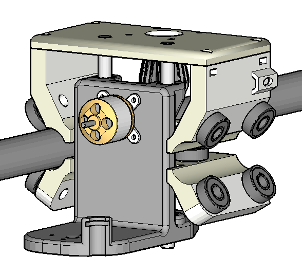
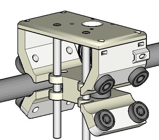
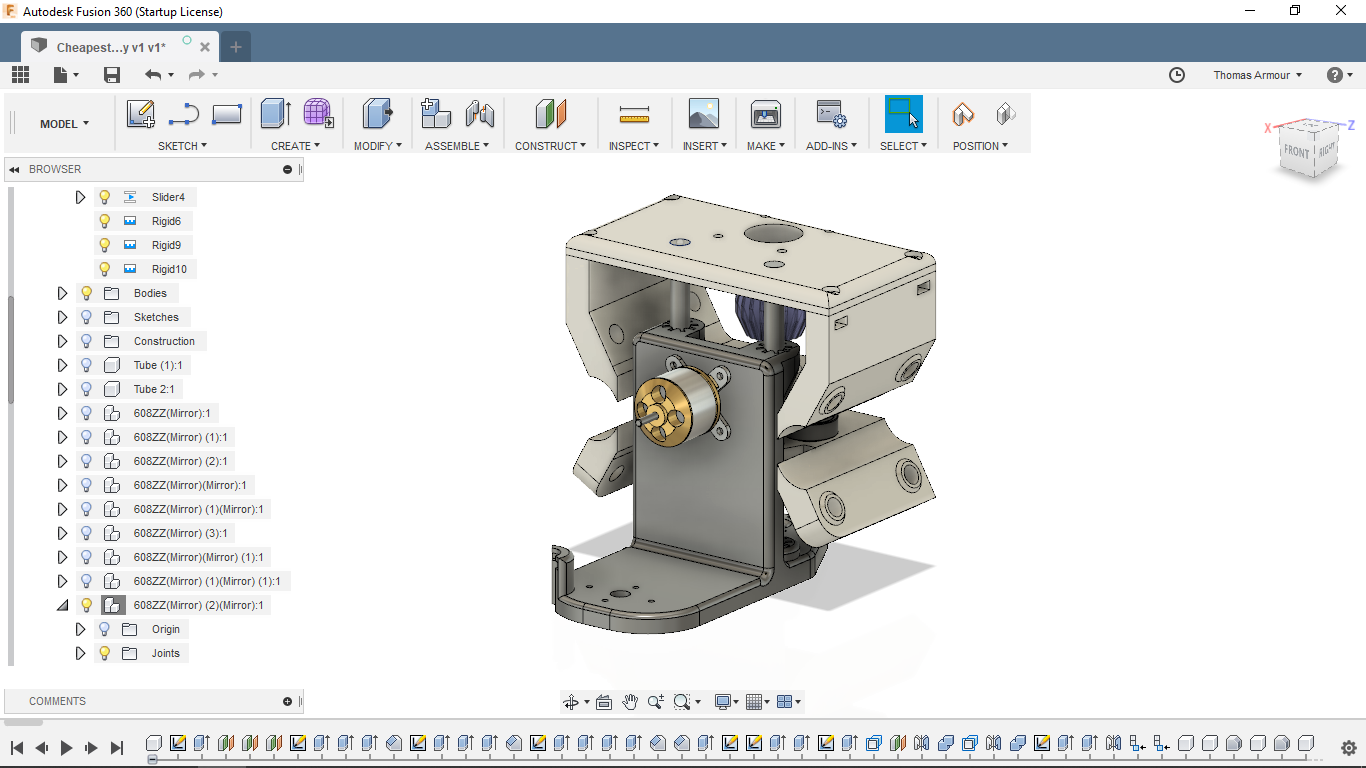
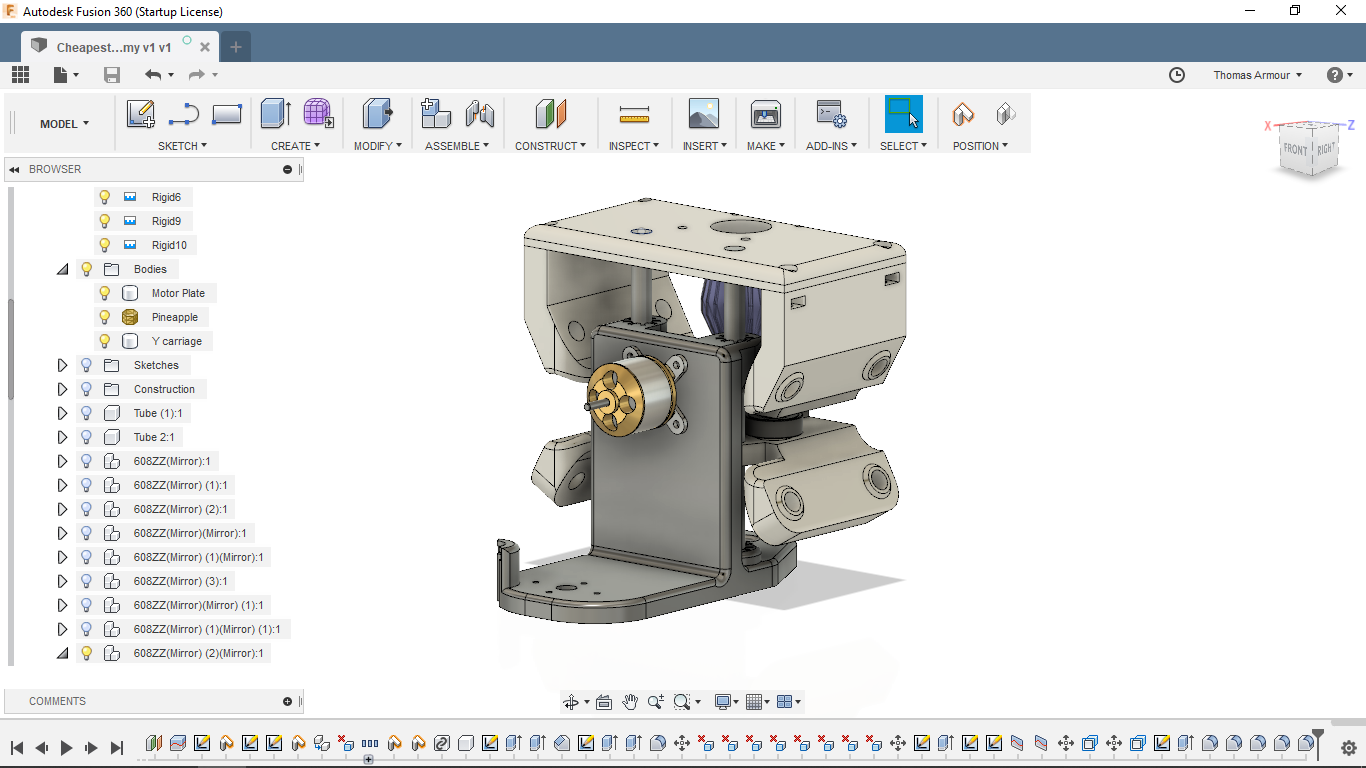
So... This is what I was talking about for reducing the cantilever effect, decreasing bearings and a slightly smaller print.

Foam Ripper Carriage 1.png
Foam Ripper Carriage 2.png
 

dkj4linux

Elite member
Thanks, Tommy. I really like your approach and would love to see more and, better yet... play with it a bit. I know that I can import/export PARASOLID, STEP, IGES, etc. from Onshape (my current preference)... I'd bet Fusion360 does also. I'm not sure the advantages of one format over the others, however... maybe you know?

Would you mind sharing those four(?) major parts, in one of those formats? It would be a great help if I can begin playing with them in Onshape vs. having to start from scratch? If you would prefer to use PM, that would be fine.

Thanks in advance. -- David
 

TEAJR66

Flite is good
Mentor
Thanks, Tommy. I really like your approach and would love to see more and, better yet... play with it a bit. I know that I can import/export PARASOLID, STEP, IGES, etc. from Onshape (my current preference)... I'd bet Fusion360 does also. I'm not sure the advantages of one format over the others, however... maybe you know?

Would you mind sharing those four(?) major parts, in one of those formats? It would be a great help if I can begin playing with them in Onshape vs. having to start from scratch? If you would prefer to use PM, that would be fine.

Thanks in advance. -- David


Well Dave, i'm an Idiot.

I did this in Sketchup. When Mark sent me the links, I downloaded the F360 files and the there was a Sketchup option so I downloaded the links in each format. The F360 files were difficult to manipulate in that the base sketches were hard for me to determine what did what where. In Sketchup, they came in as solid bodies and I am well versed at manipulating faces in SU.

I will gladly share the Sketchup models and the STL files, or whatever else format I can export them in.

As for the F360 files being ready to share any time soon, I am not sure.

I can see already that this approach has reduced the Z travel. I am sure there is still more than a foam ripper would require, but it is less than the original. I have an approach to fix that, but I won't get to it till tomorrow afternoon my time.
 

TEAJR66

Flite is good
Mentor
Wow, I really am an idiot. I just looked at it again in F360. I will be able to produce those same results in a Fusion model tomorrow. Pretty simple now that I know what I did not know.
 

dkj4linux

Elite member
Thanks, Tommy. Please don't do a lot of extra work just to get parts exported for me. I can work with Mark's STLs... and the meshes when imported into Onshape. I've done that quite a bit but thought, if you had the parts ready for easy export, I could save some time. ;)

BTW... you're NOT an idiot! :)
 

Hai-Lee

Old and Bold RC PILOT
When you switch from the needle cutter to the pen are you changing the tool and tool offsets or do you shift the work piece to get the desired results. The reason I ask is prior to actually engaging the cutter I would like to draw out or mark the advisory lines first.

Have fun!
 

dkj4linux

Elite member
I really haven't had the machine running long enough to try doing a mark-and-then-cut (or cut-and-then-mark) operation yet... but manual positioning of the gantry and carriage should yield a reasonably accurate, quick and dirty, result that may be good enough for some purposes. Not sure of "advisory lines" but I'm thinking of something like panel lines or markings on foam plane parts. Keep the work piece fixed for all operations.

I'd manually position the gantry and carriage to where I'd like the origin for pen (or needle) and then lower the pen (or needle) to place a small, but visible, mark. Set that position in as the origin (G92 X0 Y0 Z0) and make the first run. Upon completion of the run, manually move the gantry and carriage to line up the other instrument with the small mark, set that as the new origin, and make the next run.

There does seem to be some interest in doing the tool changes and offsets thing but until the combo needle-cutter/pen-holder design firms up the actual offset won't be known... but it's certainly doable.
 

Hai-Lee

Old and Bold RC PILOT
I really haven't had the machine running long enough to try doing a mark-and-then-cut (or cut-and-then-mark) operation yet... but manual positioning of the gantry and carriage should yield a reasonably accurate, quick and dirty, result that may be good enough for some purposes. Not sure of "advisory lines" but I'm thinking of something like panel lines or markings on foam plane parts. Keep the work piece fixed for all operations.

I'd manually position the gantry and carriage to where I'd like the origin for pen (or needle) and then lower the pen (or needle) to place a small, but visible, mark. Set that position in as the origin (G92 X0 Y0 Z0) and make the first run. Upon completion of the run, manually move the gantry and carriage to line up the other instrument with the small mark, set that as the new origin, and make the next run.

There does seem to be some interest in doing the tool changes and offsets thing but until the combo needle-cutter/pen-holder design firms up the actual offset won't be known... but it's certainly doable.
I must be learning because I understand everything you said in your post!

So it appears that currently you are setting the home position manually. Does your design have any provision for limit switches and so to enable an auto home, (0,0,0), detection? I have studied the designed pieces and find no real provision for them or I could just be missing something simple!

Have fun!
 

dkj4linux

Elite member
The FoamRipper, as with the MPCNC/LowRider machines it's loosely inspired by, is using the ArduinoMega/RAMPS board set and a special MPCNC-version of the Marlin firmware. It is a DIY/hobby-grade machine -- NOT your "classic" CNC -- and endstops are not required/necessary for typical home use... unless maybe you're doing repeat-fixturing and/or some tool-change jobs,

Typically, the work piece is placed/fixed anywhere in the work area, the tooling lined up to the work piece, and that position set in as "home" for the duration of that job. "Home" could therefore be in a different place every single time you use it and , if endstops were installed, you would have to re-adjust them for every single job. "Homing" and "auto-homing" functionality is therefore generally avoided on these basic machines and only serves to crash the machine as it goes off looking for non-existent, or improperly-adjusted, endstops.

That said, there are versions of Marlin/MPCNC firmware that do accommodate endstops... that are used for squaring and/or homing the machines. Typically, these machines with endstops are MUCH more difficult to set up initially than a machine without them so it is usually better for inexperienced builders to go for the basic machine first. Learn the basics and then, upon discovering you really need them, you can always add in the endstops later. This is an often discussed topic over on the MPCNC website (https://www.v1engineering.com/) and I would suggest dropping in and lurking/snooping for a while, if you haven't already.

-- David
 

moebeast

Member
I must be learning because I understand everything you said in your post!

So it appears that currently you are setting the home position manually. Does your design have any provision for limit switches and so to enable an auto home, (0,0,0), detection? I have studied the designed pieces and find no real provision for them or I could just be missing something simple!

Have fun!
If you look in the "MEDIA" tab, you will see photos of a Foam Ripper built by Wyvez. He modified my design to add limit switches. He made his side plates from cutting boards. He also modified the z-carriage to incorporate Jason's bearing guides.
 

RAGII

Member
I finally got back to working on my needle cutter. I almost got through 1 sheet of foam and then the needle broke. I am using the Moebeast method of attaching the needle to the bearing. The needle broke right at the exit of the holder. This is the second time this has happened. The first time I discovered the bearing did not spin freely so I thought that was the cause. This time the bearing spins freely. I am not positive on the RPM setting, but I hooked a 2S battery up and set the servo tester to full (1300 kv motor). When I hooke it up to my MPCNC which feeds the servo tester with 12V I tried to match the sound. It was slightly over 1/4 of the range. Cuts that were made look good.

Any thoughts on why it is breaking?

David,
I am tempted to try your design. Do you have any pictures of the through bolt from the back side?

Rob
 

dkj4linux

Elite member
Rob,

At 7.4v, a 1300kv motor should be turning, 9000 - 9500 rpm or so... that pretty fast but shouldn't be too bad if everything is balanced and turning freely. I was shocked to see that my new one was turning nearly 10k rpm, it was running so smoothly. And, yeah, at 12v it was hitting that speed with only 1/4 turn or so on the servo tester... my motor is a 1200kv motor IIRC. The slip-on flywheel seems to doing pretty well but I've only cut a bit more than one sheet so far... so I really don't know yet how well it's going to hold up. It still seems tight and there's no slop that I can detect.

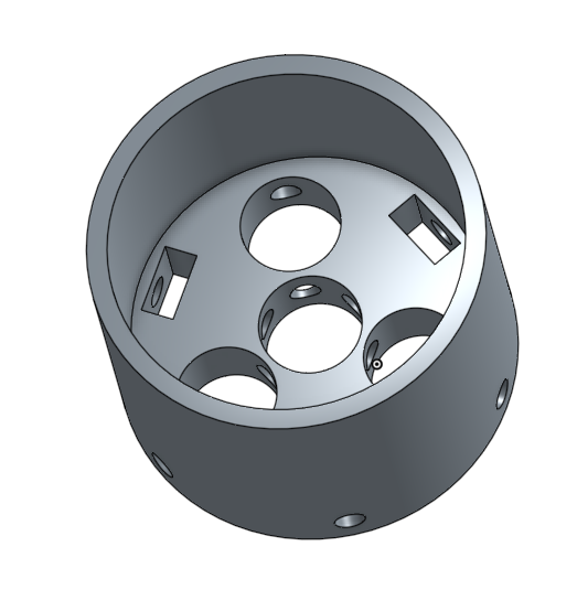
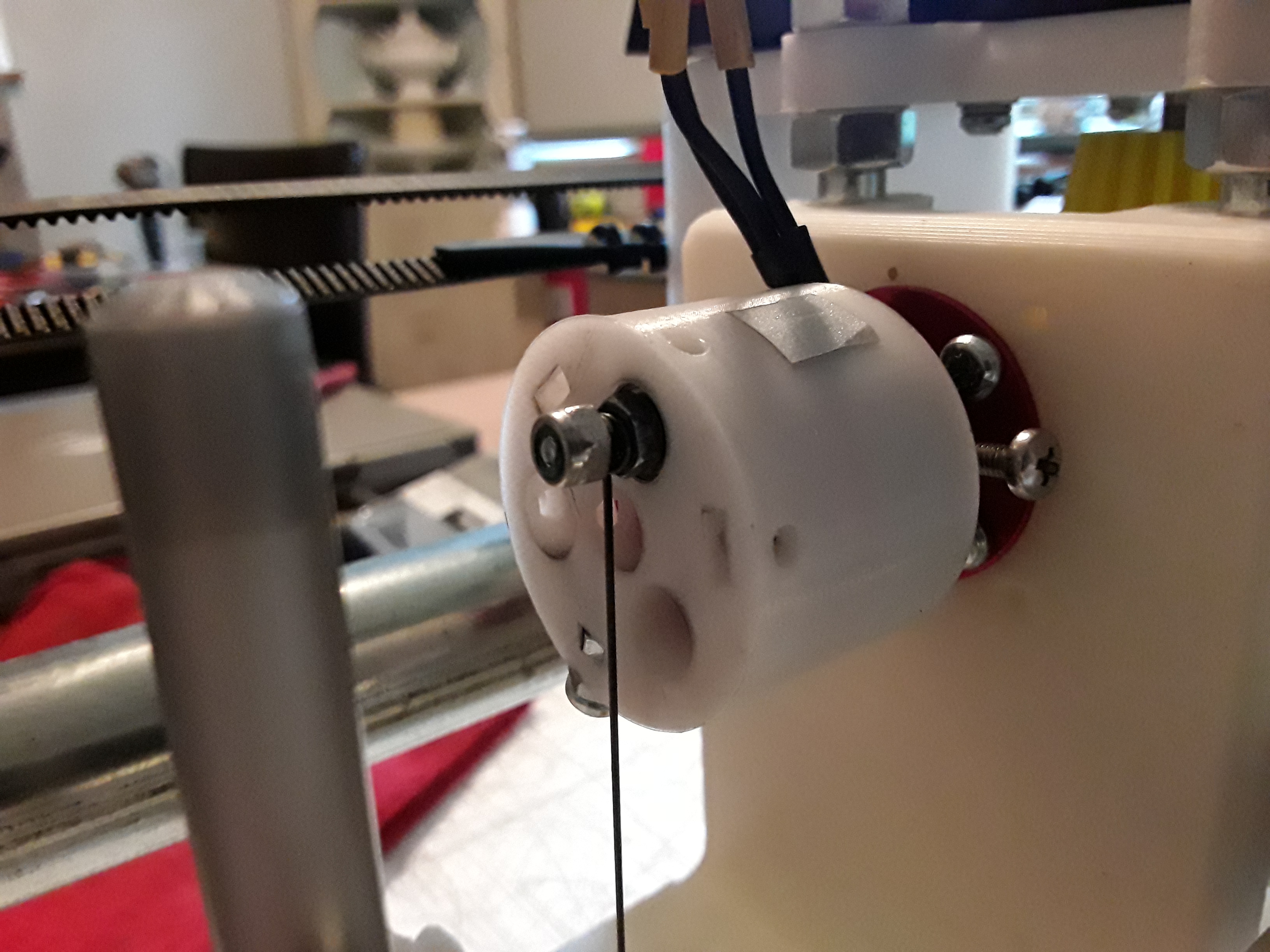
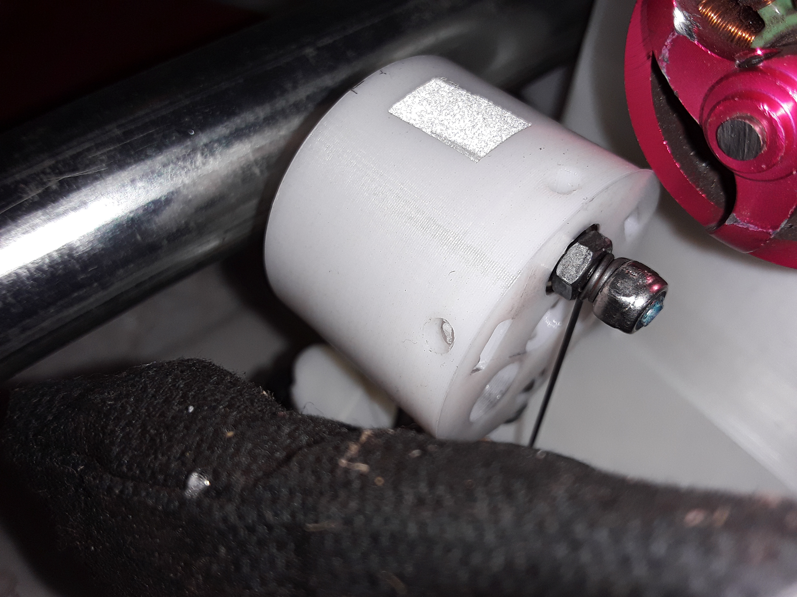
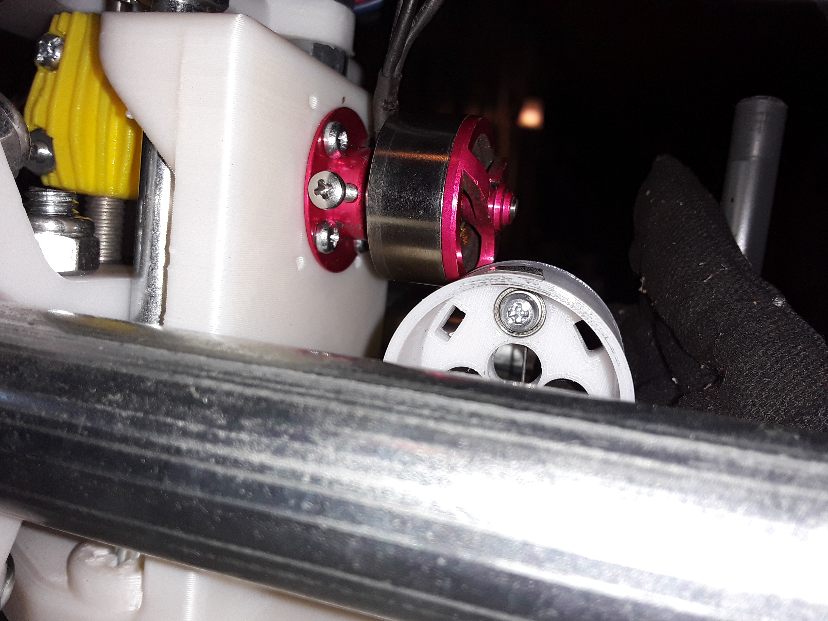
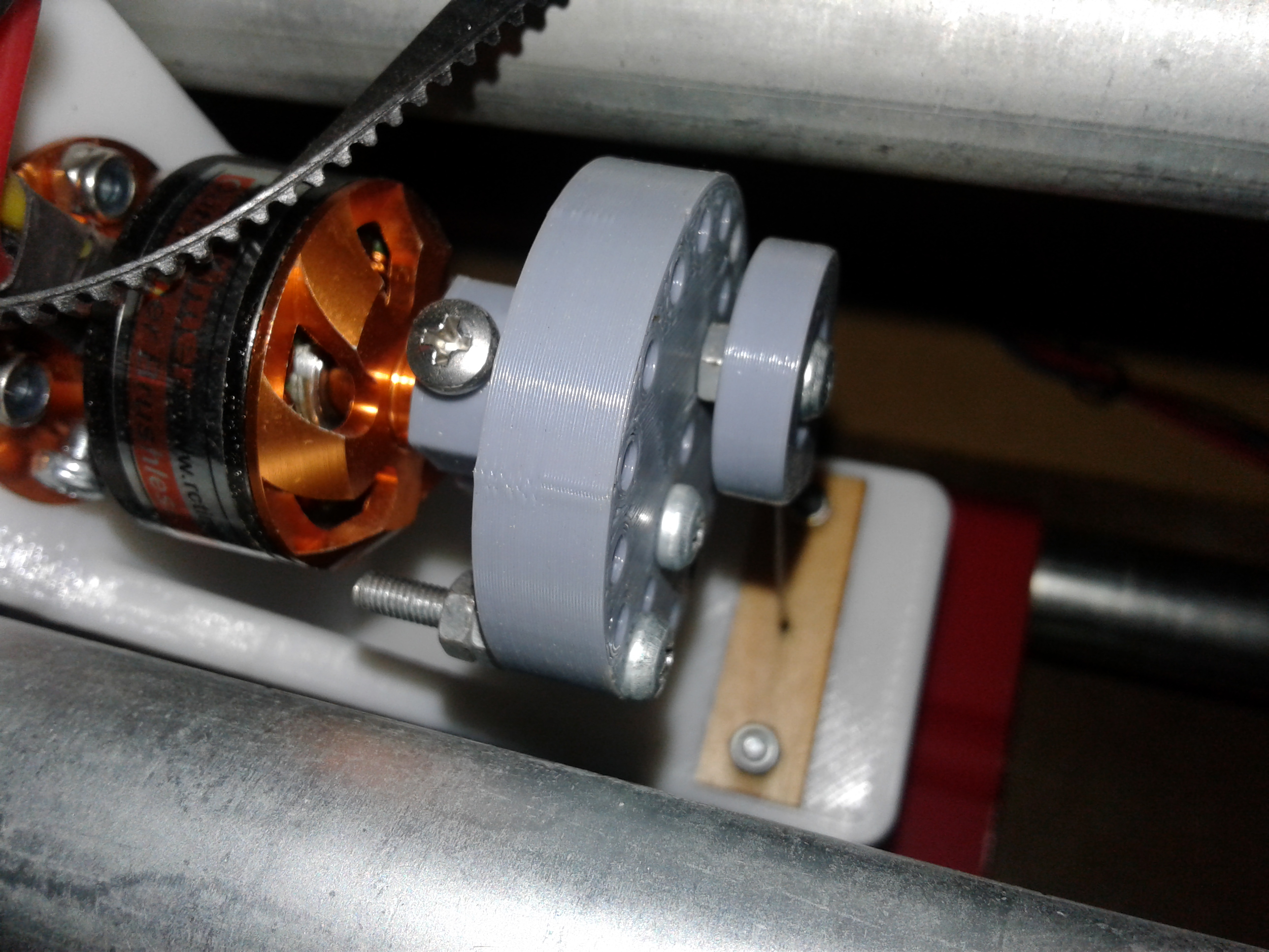
So, is it ready for prime-time? I don't know... but I like what I see so far with the one I'm messing with now. If you've got your 3d printer well-tuned and dialed-in (calibrated) you're certainly free to give it a try. The big trick with it is that everything is a nice, slight pressure to seat, friction fit... flywheel onto motor bell, and eccentric bearing into one of the 3 holes in the face. It will need to be custom fit to both your motor and the bearing you'll be using. My motor bell measured 28.65mm and the ID of the flywheel cup is set at 28.7mm... the bearing measures 8mm OD and the 3 central holes in the face are 8.075mm ID. Whether I get that precision is probably wishful thinking but it seems to work... when it was close, I was able to sneak up on it. It's saving grace is that it is a pretty quick print... only 20 minutes or so IIRC. All the rest of the hardware is 3mm. Remember also that the motor shaft will need to be cut off (wait until you have a flywheel that fits!)... so the motor will only be suitable for this purpose in the future.
slip-on_flywheel.png

20180904_180425.jpg


20180904_180507.jpg


20180904_180714.jpg


20180904_181415.jpg


20180904_181440.jpg


If you're so inclined, here's the link to the Onshape model...

https://cad.onshape.com/documents/f...791af04b9c36763e65d7/e/dfa156ec6f77c140a8adb6

I don't know what motor you are using so I doubt my STL would fit... but it would be a quick print and give you something to inspect and ponder over... hopefully there's an attached STL file.

If you can give me the exact motor and bearing information, I could pretty quickly create a new STL from the Onshape model for you. It's your call.

Good luck. -- David
 

Attachments

  • slip-on_flywheel-Emax_CF2822.stl
    709.5 KB · Views: 0
Last edited:

dkj4linux

Elite member
.. I am using the Moebeast method of attaching the needle to the bearing. The needle broke right at the exit of the holder. This is the second time this has happened. The first time I discovered the bearing did not spin freely so I thought that was the cause. This time the bearing spins freely.
...

Rob, I've not actually used Mark's needle holder... IIRC it has a keeper "ledge/flange" on the flywheel side of the bearing cavity? When you say your bearing is spinning freely... that's with the holder and needle in place?

The keeper/holder I did for my Phlatprinter-style machine didn't have the "ledge/flange"... it simply slipped on from the front. I never had it fly off on me... granted, I didn't do a lot of cutting with that machine -- just a couple of sheets -- so I may just have been lucky. For your needle to break at the exit from the holder indicates to me that your holder wasn't rocking freely from one side to the other. Are you sure that the holder fits nicely on the bearing and wasn't rubbing against the face of the flywheel? It needs to be spaced out from the face a bit for clearance. Also, is the needle guide and holder aligned nicely -- holder directly over the guide(s) -- as in the photo below?

180908_3dfa0196c442ee31b7dd5bcac3657ed8.jpg


180910_db29a96ce301b3e8edcbce82dba6b990.jpg
 
Last edited:

RAGII

Member
David,

I do not have the keeper spaced out as far as the one in the picture, but I do have some shims on the bearing to keep it spaced out a little. In my dry run the blur looked to be good and consistent, but I might want to space it out some more and give it a try. After I posted I noticed that the motor mount screws were really loose, most not have had good engagement with the screws in the PLA. It does seem to line up well with the guide (within a mm I would say).

I am using an EMAX motor like you are, just a little smaller. The housing may be the same, but if not I can adjust the Onshape file. You and Jason got me hooked on using it so I enjoy working in it to get better at modeling.

Thanks for the model, I wasn't sure if you had a flange the bearing sat against or if it was also a friction fit.

Thanks again, off to try some more.

Rob
 

dkj4linux

Elite member
Okay... all's good :)

Finally got FoamRipper in shape to cut those three sheets of DTFB for the vacuum pad... and things went quite well. No interrupts or squirrely things happened and all three sheets were completed and look reasonable. It's getting late though and I've found through many years of experience that when I start something late in the evening is when I start making stupid mistakes... so I'll just finish my beer while trying to get this posted and wait until tomorrow to see if I can finish this sucky job ;)

A brief video (turn down the sound!) showing the needle cutter cutting vertical slots in a sheet of DTFB... also note the cable support that flexes while still holding the cables clear of the workpiece... one of those giant nylon cable ties from the hardware store :cool:


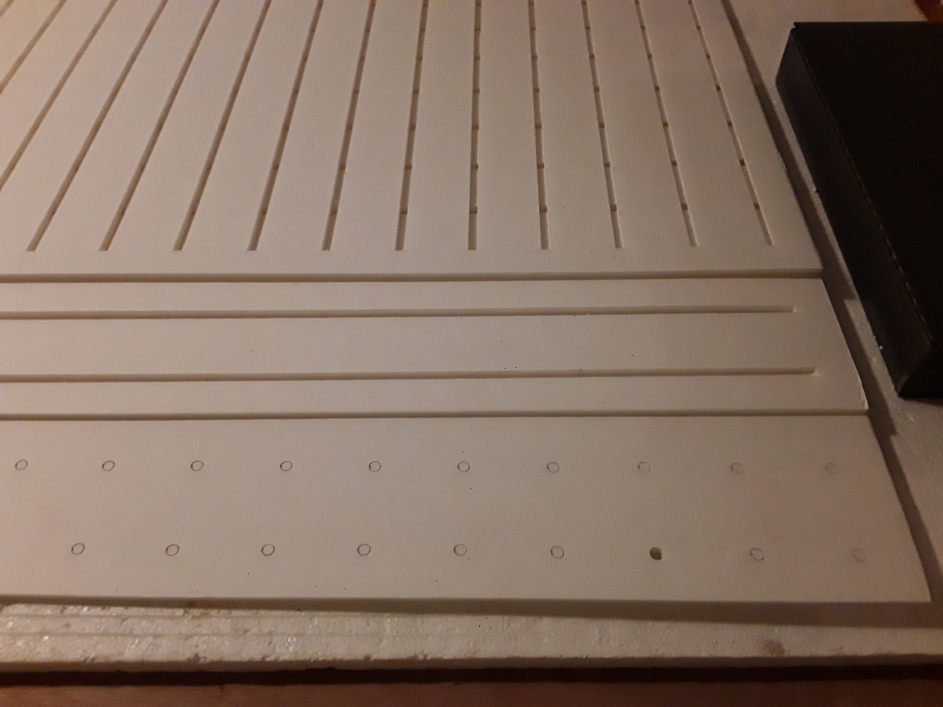
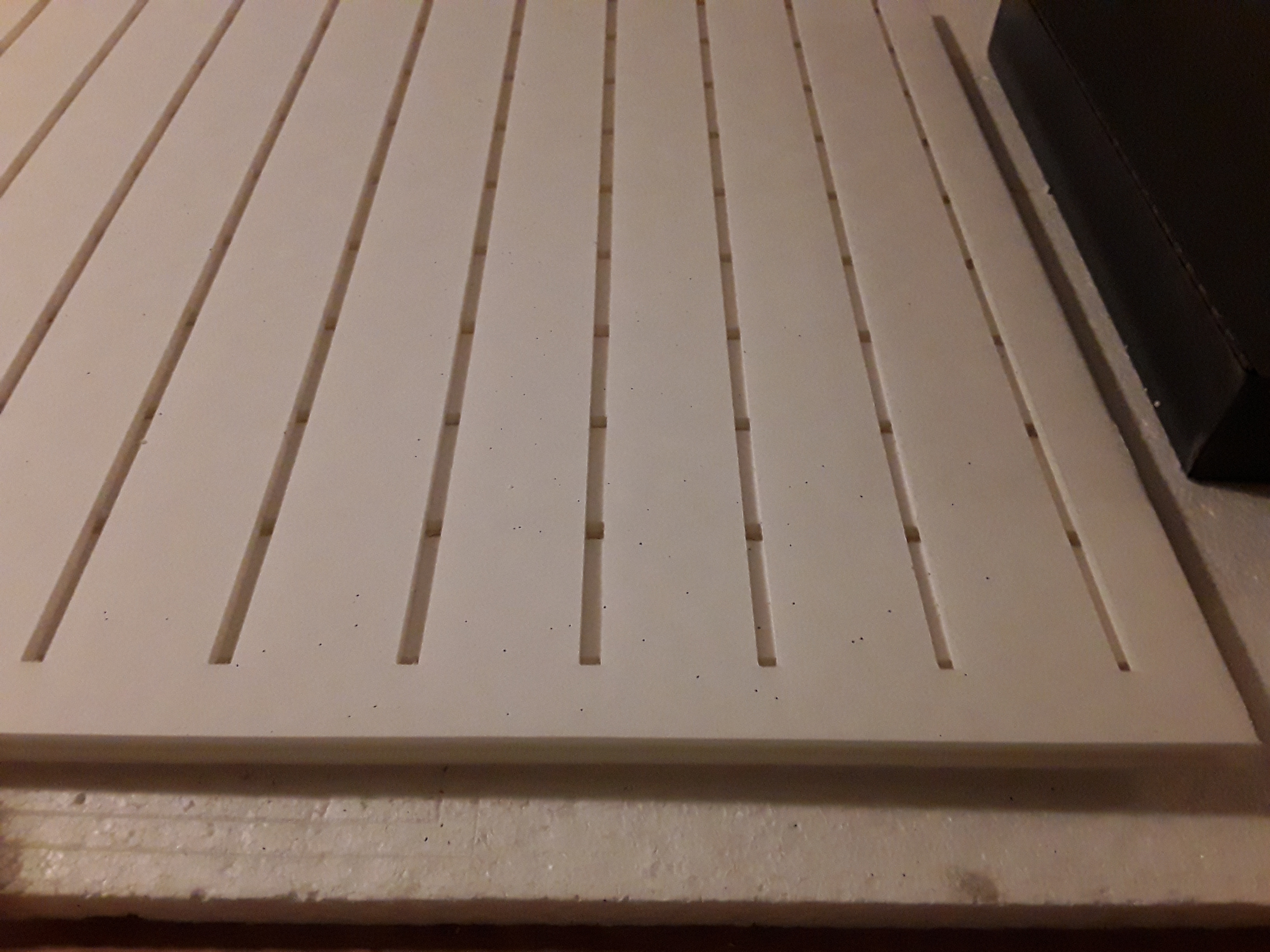
And photos showing the three sheets of DTFB for the vacuum pad...

20180904_223809.jpg


20180904_223733.jpg


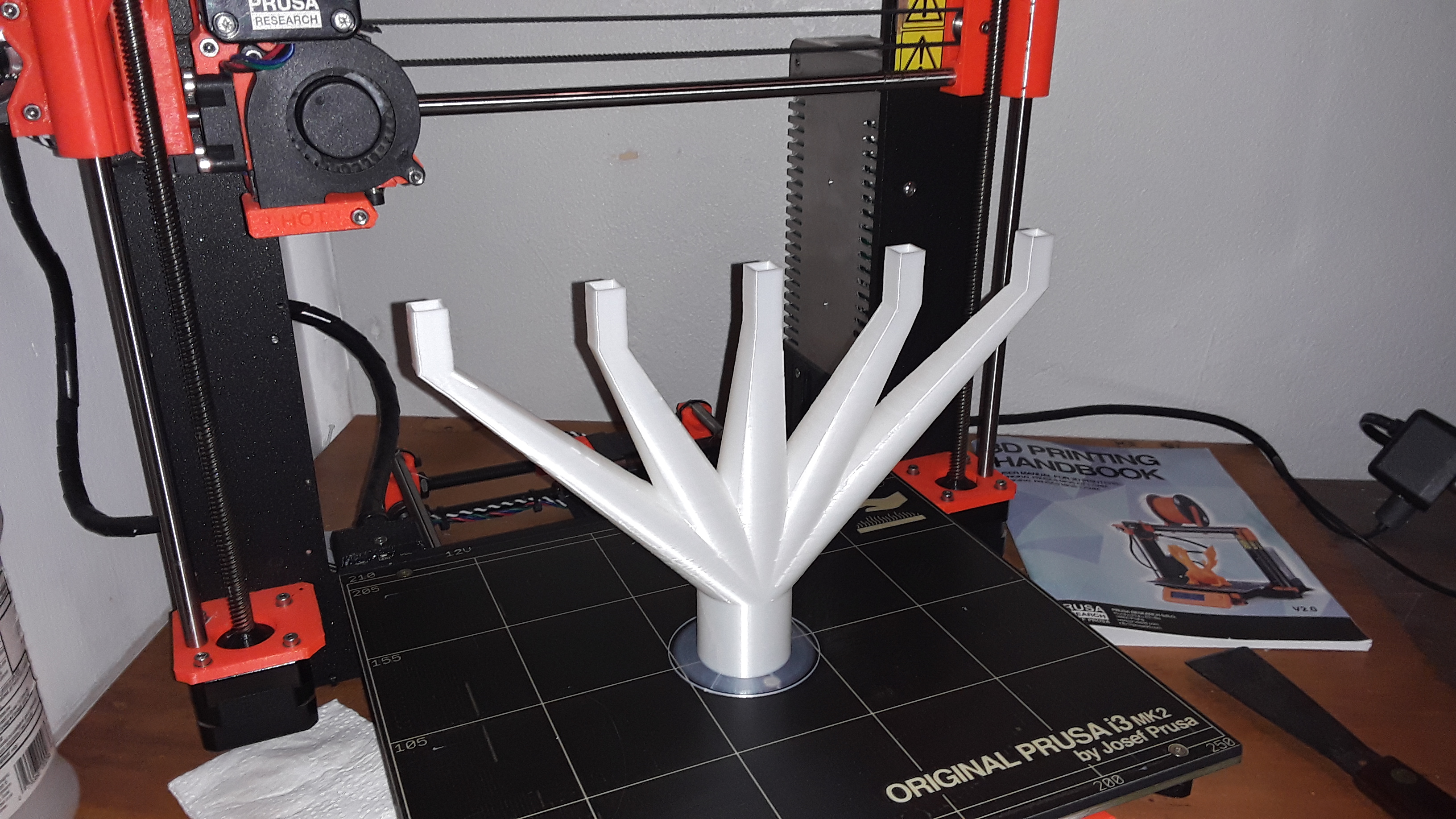
I know it's hard to see in that last photo but the idea is to stack 3 sheets of foam board... one with vertical slots, one with horizontal slots, and a top sheet with holes that line up with all the slot intersections... they're shown in reverse order in the photos (because I'm too lazy/tired to clear all the "donut holes"/confetti out of the holes sheet at the moment). I've printed Mark's sexy plenum... which is slotted/fitted in the end of the stack, on the two bottom layers (the slotted ones), and then a shop vac is hooked to the plenum.

20180828_215056.jpg


positioned like so...

20180829_111719.jpg


In the simplest case, the stack (probably best if glued up with some of repositionable spray glue) is placed on the work surface (if smooth enough) and the piece to be cut is placed on top of the stack, over the holes layer. Lightly pressed down flat, the vacuum should take hold and the entire stack, along with the workpiece, is sucked down onto the work surface... hopefully under the tool head of your CNC :eek:

The top layer of the stack, the "holes" sheet, becomes the sacrificial layer and will eventually have to be replaced... but that should be many sheets down the road. A sheet of DTFB from the local dollar store, 15-20 minutes cutting the holes in the sheet, and you should be back in business :)

Speaking of sheets to the wind... er, sheets down the road... ah, sheets...

Nite all!

-- David
 
Last edited: