A new hot wire cutter build thread - One cubic meter volume

NM156

Member
For some crazy reason I decided to build another CNC hot wire cutter. This is going to be much larger than the one I currently have. It's going to be one cubic meter in size. I don't plan on cutting anything that large, but the dimensions will provide a steeper cutting angle and allow cutting more parts in a single run.

The frame will be primarily be 2040 extruded aluminum. I'll be re-using the electronics box from the current hot wire machine. It will be configured to use both a tension spring and bow for the wire itself.

In a total overkill decision, linear motion will be guided by MGN12 rails.

There will be two frames (X/Y and U/V axes) mirrored to each other. 1/8" aluminum will be CNC milled into the necessary brackets and mounts. 3D printed parts will round out the build for additional bracing, foot mounting brackets and wire management.

I can make all of the STLs and DXFs available if there is interest.

Let's get this project rolling...

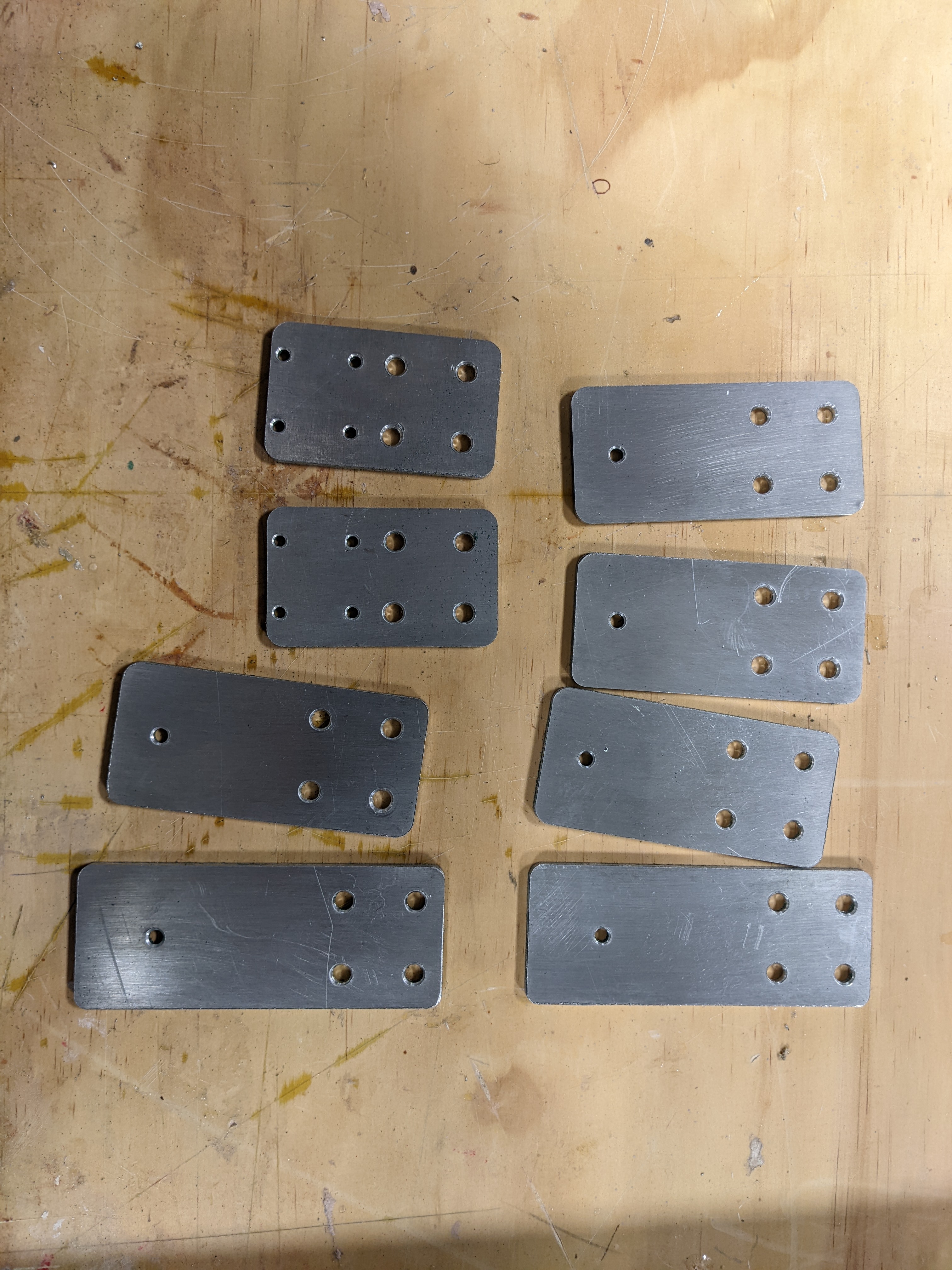
Cutting the aluminum parts.

PXL_20220217_190653384.MP.jpg
PXL_20220217_203144480.jpg
PXL_20220218_150321329.jpg


A little bit of cleanup on a Scotch-Brite wheel and these are ready.


In the background the 3D printers were cranking away making more parts

Mounting brackets for the feet

PXL_20220219_140411990.jpg


Making wire management clips

PXL_20220219_204855959.MP.jpg


Corner braces (gyroid infill)

PXL_20220219_204910380.jpg
 

FlamingRCAirplanes

Elite member
For some crazy reason I decided to build another CNC hot wire cutter. This is going to be much larger than the one I currently have. It's going to be one cubic meter in size. I don't plan on cutting anything that large, but the dimensions will provide a steeper cutting angle and allow cutting more parts in a single run.

The frame will be primarily be 2040 extruded aluminum. I'll be re-using the electronics box from the current hot wire machine. It will be configured to use both a tension spring and bow for the wire itself.

In a total overkill decision, linear motion will be guided by MGN12 rails.

There will be two frames (X/Y and U/V axes) mirrored to each other. 1/8" aluminum will be CNC milled into the necessary brackets and mounts. 3D printed parts will round out the build for additional bracing, foot mounting brackets and wire management.

I can make all of the STLs and DXFs available if there is interest.

Let's get this project rolling...

Cutting the aluminum parts.

View attachment 219522 View attachment 219523 View attachment 219524

A little bit of cleanup on a Scotch-Brite wheel and these are ready.


In the background the 3D printers were cranking away making more parts

Mounting brackets for the feet
View attachment 219525


Making wire management clips

View attachment 219526


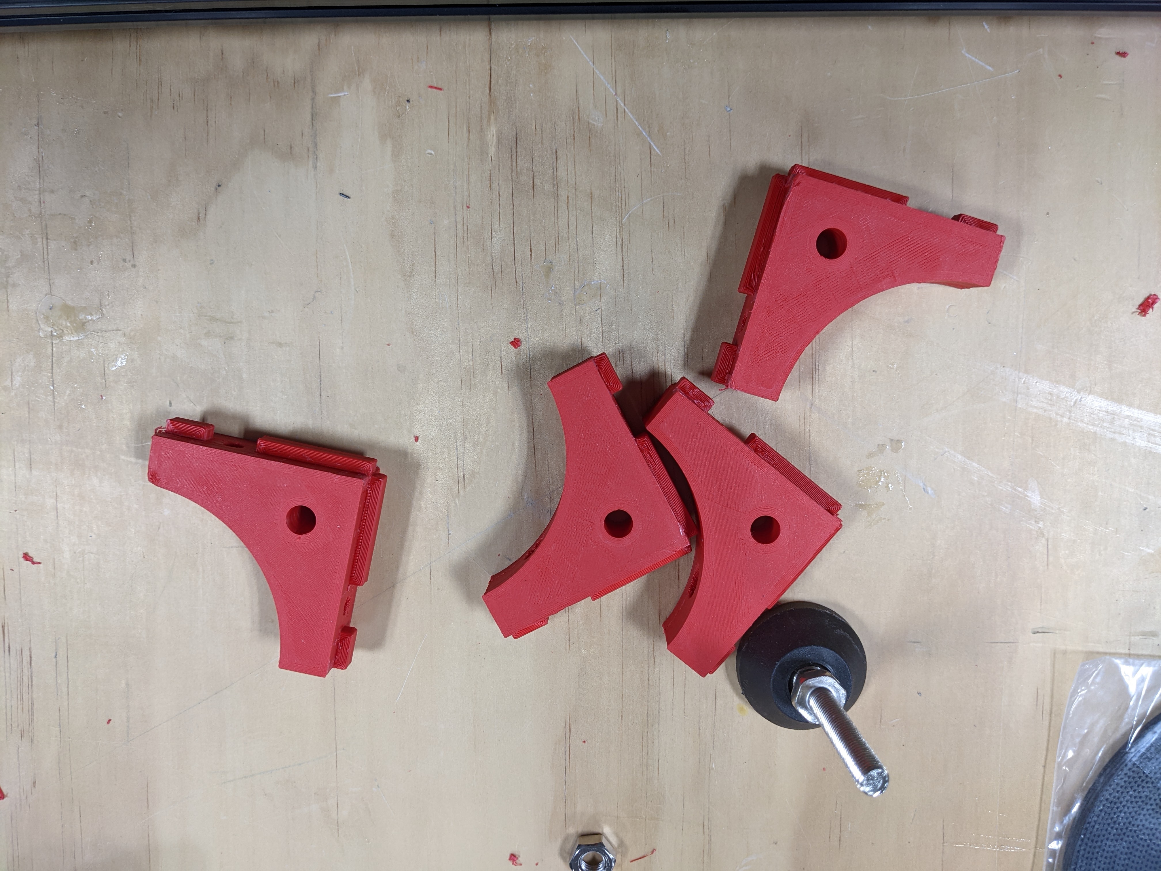
Corner braces (gyroid infill)

View attachment 219527
Lets goooo!!!!!!!!!!
 

NM156

Member
Now that I have some basic parts created, I can start the assembly.


3D printed alignment tools for 12mm rail to 20mm extrusion.

PXL_20220216_170147132.jpg


Attaching the MGN12 rails to the extrusions. The alignment tools help center the rail over the extrusion.
I prefer the slide-in tee nuts as opposed to the drop in type and use them when possible.

PXL_20220216_165948448.jpg


Internal corner braces (Most for assembly convenience, the load will be carried by the Aluminum and 3D printed brackets)
I had them on hand, so I'll just use them...
PXL_20220216_170812099.MP.jpg


The basic layout of one side frame. The final orientation is vertical. The X axis will be driven from both the top and bottom by a double shafted NEMA17 motor. This helps avoid racking caused by driving only a single side. GT2 belts will be used,

PXL_20220216_182758169.jpg


Y/V Axis attachment plate to the X/U axis

PXL_20220217_212639846.jpg


I had to use drop in tee nuts here, I'm temporarily out of slide in tee-nuts. I'll replace these when I replenish my supply.

Awaiting the double shafted motors for the X/U axes drive. Expected to be here Tuesday.
Flange bearings arrived today and also the shaft couplers for the motors. I couldn't find any 5mm to 6.35mm couplers with a quick delivery, so I ordered some 5mmx5mm adapters that I'll chuck in the lathe and open up one half to 1/4".

Started printing some more parts tonight, more 3D braces for the bed and some GT2 belt joiners.

Tomorrow I'll CNC the final 4 pieces for the X/U drive, and cut some aluminum angle for the Y/V drive connections. Then I should be able to connect all of the subassemblies.
 

FlamingRCAirplanes

Elite member
Now that I have some basic parts created, I can start the assembly.


3D printed alignment tools for 12mm rail to 20mm extrusion.

View attachment 219689

Attaching the MGN12 rails to the extrusions. The alignment tools help center the rail over the extrusion.
I prefer the slide-in tee nuts as opposed to the drop in type and use them when possible.

View attachment 219690

Internal corner braces (Most for assembly convenience, the load will be carried by the Aluminum and 3D printed brackets)
I had them on hand, so I'll just use them...
View attachment 219691


The basic layout of one side frame. The final orientation is vertical. The X axis will be driven from both the top and bottom by a double shafted NEMA17 motor. This helps avoid racking caused by driving only a single side. GT2 belts will be used,

View attachment 219692

Y/V Axis attachment plate to the X/U axis

View attachment 219694

I had to use drop in tee nuts here, I'm temporarily out of slide in tee-nuts. I'll replace these when I replenish my supply.

Awaiting the double shafted motors for the X/U axes drive. Expected to be here Tuesday.
Flange bearings arrived today and also the shaft couplers for the motors. I couldn't find any 5mm to 6.35mm couplers with a quick delivery, so I ordered some 5mmx5mm adapters that I'll chuck in the lathe and open up one half to 1/4".

Started printing some more parts tonight, more 3D braces for the bed and some GT2 belt joiners.

Tomorrow I'll CNC the final 4 pieces for the X/U drive, and cut some aluminum angle for the Y/V drive connections. Then I should be able to connect all of the subassemblies.
Man this is beautiful
 

Flightspeed

Convicted Necroposter
So is this basically a diy version of what Flitetests been using for the b17? Have you ever used that kind of foam or do u use the pink stuff.
 

NM156

Member
So is this basically a diy version of what Flitetests been using for the b17? Have you ever used that kind of foam or do u use the pink stuff.

That is correct.

I've used several different types of foam. The white stuff (styrofoam) tends to be more convenient because it comes in many different densities. The pink and blue are usually available in a single density (as and insulation) and are typically heavier.