Cutting foam sheets... with a needle!

Springer

Member
Ha, David, you beat me to it I had to go downstairs to get my crib sheet of Grbl commands! Michael, it will be worth it to do the $$ command from the console in UGS, and print them out or write them down like I did (so low tech!). I had to increase the max travel $130 to 610 (mm), $131 to 1220, $132 to 50 for my unit.
 

Michael9865

Elite member
Hey Michael! Hope this finds you well.
Since you're runnng Grbl, I'd do the "$$" thing from the console and check out the $20 and $21 values first... soft limit enable and hard limit enable, resp. Then check $130, $131, and $132 to see that they match your machine's extents for X/Y/Z, resp. Then I suppose you'd need to check for your machine extent settings in Estlcam... don't remember off the top of my head where it's set but I'm pretty sure it's there someplace. Get them all matched up across you whole workflow and hopefully things will start working for you.
Good to hear from you. Let me know how it goes. -- David
Ha, David, you beat me to it I had to go downstairs to get my crib sheet of Grbl commands! Michael, it will be worth it to do the $$ command from the console in UGS, and print them out or write them down like I did (so low tech!). I had to increase the max travel $130 to 610 (mm), $131 to 1220, $132 to 50 for my unit.

First off, yes, I am well thank you for asking. I pray that you all are also doing well.
I did the $$ and lines $130-$132 looked good to me. Not sure about lines $20-$21.
Here is the dump I got from $$.
Current Arduino Settings
$0=10 (step pulse, usec)
$1=25 (step idle delay, msec)
$2=0 (step port invert mask:00000000)
$3=0 (dir port invert mask:00000000)
$4=0 (step enable invert, bool)
$5=0 (limit pins invert, bool)
$6=0 (probe pin invert, bool)
$10=3 (status report mask:00000011)
$11=0.010 (junction deviation, mm)
$12=0.002 (arc tolerance, mm)
$13=0 (report inches, bool)
$20=0 (soft limits, bool)
$21=0 (hard limits, bool)
$22=0 (homing cycle, bool)
$23=0 (homing dir invert mask:00000000)
$24=25.000 (homing feed, mm/min)
$25=500.000 (homing seek, mm/min)
$26=250 (homing debounce, msec)
$27=1.000 (homing pull-off, mm)
$100=12.562 (x, step/mm)
$101=12.562 (y, step/mm)
$102=283.460 (z, step/mm)
$110=500.000 (x max rate, mm/min)
$111=500.000 (y max rate, mm/min)
$112=500.000 (z max rate, mm/min)
$120=10.000 (x accel, mm/sec^2)
$121=10.000 (y accel, mm/sec^2)
$122=10.000 (z accel, mm/sec^2)
$130=1219.000 (x max travel, mm)
$131=609.000 (y max travel, mm)
$132=50.000 (z max travel, mm)

FYI - when I try the visualize button in UGS I get this error.
WARNING: An illegal reflective access operation has occurred
WARNING: Illegal reflective access by com.jogamp.common.os.NativeLibrary$3 (file:/home/michael763/UniversalGcodeSender.jar) to method java.lang.ClassLoader.findLibrary(java.lang.String)
WARNING: Please consider reporting this to the maintainers of com.jogamp.common.os.NativeLibrary$3
WARNING: Use --illegal-access=warn to enable warnings of further illegal reflective access operations
WARNING: All illegal access operations will be denied in a future release
Inconsistency detected by ld.so: dl-lookup.c: 111: check_match: Assertion `version->filename == NULL || ! _dl_name_match_p (version->filename, map)' failed!
I am not sure if that means I have something not set correctly in Linux/UGS. Is it related or not, IDK. Too much of a NOOB to this side of it.

Back to the original issue. I cannot see in ESTCAM Gcode side where I would set the X,Y,Z limits. Here is some of the settings. The third and fourth photo show setting for ESTLCAM's cnc controller that I don't use.

IMG_0500.jpg IMG_0501.jpg IMG_0502.jpg IMG_0503.jpg
 

Springer

Member
Don't know about the error you were getting, but you might make the travel limits in estcam (2nd picture "home amd travel") match the numbers you sent using universal gcode sender. I haven't used estcam, so can't speak with any authority. Since you are using sketchup to design, you might get wafer to generate your gcode. I probably have already mentioned it to you but it is a plugin, and I have been using it for everything gcode, laser and needler. The only downside is you have to enter or edit speeds and feeds in the .nc files with notepad, but I find that easy using find/replace. Maybe try it and see if you get the same error. https://www.rcgroups.com/forums/sho...M-tools-for-sketchup-users-SU-to-Gcode-plugin
 

dkj4linux

Elite member
This seems very much a Java thing... Googling the exact error messages points to a lot of different programs and Java versions. Apparently you'll need to get a proper combo of all those things lined up to keep it from squawking about "illegal reflective access" (whatever that is...).

A couple of things come to mind. I'd try a different sender program with Linux (RepetierHost, bcnc, grblcontroller, etc) and/or use your Windows laptop to run UGS, or other sender program.

I personally don't use those sender programs anymore... instead using an RPi, running V1Pi/CNC.js, and connected to the GRBL controller thru USB. The Pi serves up a web page over wifi that allows remote control through my Chrome browser. It sounds a bit more complicated than it really is but I prefer CNC.js to any of the other sender programs I've used.
 

dkj4linux

Elite member
Speaking of SketchUp... I started with that years ago and found the Phlatboyz/SketchUCAM plugin to be very easy to use. SketchUCAM is still available from the Openbuilds website... and they're friendly folks. It may require registration but it's free and painless. My late flying/fishing buddy and I used it to do the gcode for a whole fleet of fanfold foamy airplanes we'd build and fly in my pasture. I even used it to CAM up and cut all the parts for a CNC machine for my buddy.
 

Michael9865

Elite member
Don't know about the error you were getting, but you might make the travel limits in estcam (2nd picture "home amd travel") match the numbers you sent using universal gcode sender. I haven't used estcam, so can't speak with any authority. Since you are using sketchup to design, you might get wafer to generate your gcode. I probably have already mentioned it to you but it is a plugin, and I have been using it for everything gcode, laser and needler. The only downside is you have to enter or edit speeds and feeds in the .nc files with notepad, but I find that easy using find/replace. Maybe try it and see if you get the same error. https://www.rcgroups.com/forums/sho...M-tools-for-sketchup-users-SU-to-Gcode-plugin

This seems very much a Java thing... Googling the exact error messages points to a lot of different programs and Java versions. Apparently you'll need to get a proper combo of all those things lined up to keep it from squawking about "illegal reflective access" (whatever that is...).
A couple of things come to mind. I'd try a different sender program with Linux (RepetierHost, bcnc, grblcontroller, etc) and/or use your Windows laptop to run UGS, or other sender program.
I personally don't use those sender programs anymore... instead using an RPi, running V1Pi/CNC.js, and connected to the GRBL controller thru USB. The Pi serves up a web page over wifi that allows remote control through my Chrome browser. It sounds a bit more complicated than it really is but I prefer CNC.js to any of the other sender programs I've used.

Mike, I will read through that thread and ”do some learning.” I will update those numbers and see what the results are.

David, The RPi sounds interesting. I have a friend who keeps telling me to try RPi. Also the Java on my machine is 11.06. I will also google the errors and see if I can understand what I read.LOL

Thank you both for your input.
 

dkj4linux

Elite member
Michael,

Here's an example of a Pi (in this case, a Pi ZeroW... with built-in wifi) connected through USB to a Nano-based 3-axis Grbl controller, running my R&P MPCNC.

20200131_231203.jpg


The RPi is loaded with the @jeffeb3's V1Pi image... a Linux system, preloaded with both Octoprint and CNC.js, and which also serves up a webpage that I then access and control through the Chrome browser on my "recliner" Chromebook. Both CNC.js and Octoprint are camera-enabled... with Octoprint able to do time-lapse as well. Normally, the RPi is a full-size Pi (usually a 3B+, for me)... especially if using the camera functionality.

Here I am *in action*...

20191113_092317.jpg


Slippers, a darkened room, a glass of Merlot, a movie, Prusa printer, and MPCNC laser engraver -- all busy and in "eye-shot". My recliner Chromebook, with CNC.js in a browser tab controlling MPCNC "Joe", which is laser engraving a V1Engineering logo... all while Tux monitors what's going on. Never been more productive... ;)

-- David
 

delli1221

New member
dkj4linux said:
The RPi is loaded with the @jeffeb3's V1Pi image... a Linux system, preloaded with both Octoprint and CNC.js, and which also serves up a webpage that I then access and control through the Chrome browser on my "recliner" Chromebook. Both CNC.js and Octoprint are camera-enabled... with Octoprint able to do time-lapse as well. Normally, the RPi is a full-size Pi (usually a 3B+, for me)... especially if using the camera functionality.
I'd say you've got your ducks in a row there David. I've been quietly following along and have been making my way through this thread off and on for a couple of days now. I've been trying to gather info about needle cutting/Gcode/Linux and so on before my ERC TimSav kit arrives and I wanted to ask you what version of jeffeb3's V1Pi image you are running on your Pi zero W? It looks like a great fit for this small form factor needle cutter.

Thanks for starting this thread and sharing your knowledge with the community!

Daniel
 

dkj4linux

Elite member
I'd say you've got your ducks in a row there David. I've been quietly following along and have been making my way through this thread off and on for a couple of days now. I've been trying to gather info about needle cutting/Gcode/Linux and so on before my ERC TimSav kit arrives and I wanted to ask you what version of jeffeb3's V1Pi image you are running on your Pi zero W? It looks like a great fit for this small form factor needle cutter.

Thanks for starting this thread and sharing your knowledge with the community!

Daniel
Hey, Daniel! Welcome to the party! And thank you for the kind words.

I don't think I have the latest V1Pi image on any of my RPi's. I'm probably a couple of versions behind... and I've been able to move the same SD card between Pi 3B+ and Pi ZeroW without issue. These are working and I'm one of those "don't fix it if it ain't broke" kinda guys... so I really don't feel compelled to go get a new image. All my machines are pretty basic and I rarely push any of my machines to the limit... so basic functionality is usually good enough for me. This V1Pi link will take you to Jeff's latest and greatest and give you a lot more information on which RPi's you can use, and when to use them. But you're right... the Pi ZeroW and the ERC TimSav are a great match. I don't really need another needle cutter (I'm no longer building and flying planes...) so my initial TimSav build was less the needle cutter... but the servo functionality is in place with this Eleksmaker Mana SE v3.2 2-axis Grbl controller connected to the Pi ZeroW...

1586569439686.png


Again, welcome!

-- David
 

Michael9865

Elite member
Michael,
Here's an example of a Pi (in this case, a Pi ZeroW... with built-in wifi) connected through USB to a Nano-based 3-axis Grbl controller, running my R&P MPCNC.
The RPi is loaded with the @jeffeb3's V1Pi image... a Linux system, preloaded with both Octoprint and CNC.js, and which also serves up a webpage that I then access and control through the Chrome browser on my "recliner" Chromebook. Both CNC.js and Octoprint are camera-enabled... with Octoprint able to do time-lapse as well. Normally, the RPi is a full-size Pi (usually a 3B+, for me)... especially if using the camera functionality.
Here I am *in action*...
Slippers, a darkened room, a glass of Merlot, a movie, Prusa printer, and MPCNC laser engraver -- all busy and in "eye-shot". My recliner Chromebook, with CNC.js in a browser tab controlling MPCNC "Joe", which is laser engraving a V1Engineering logo... all while Tux monitors what's going on. Never been more productive... ;)
-- David

David,
Would this board work to talk to the Arduino CNC Shield that I already have?
https://www.amazon.com/dp/B07BDR5PDW/?tag=lstir-20

Also, I like the drive system of your R&P MPCNC. Does the the rack thread sections attach to the conduit with the clips? How do the rack thread sections connect to each other? Getting rid of the belts would be a nice idea.

I wonder if I have too much time on my hands at this moment. LOL
I ordered some more foam and supplies from Mike last night also.
 

delli1221

New member
dkj4linux said:
Hey, Daniel! Welcome to the party! And thank you for the kind words.

I don't think I have the latest V1Pi image on any of my RPi's. I'm probably a couple of versions behind... and I've been able to move the same SD card between Pi 3B+ and Pi ZeroW without issue. These are working and I'm one of those "don't fix it if it ain't broke" kinda guys... so I really don't feel compelled to go get a new image. All my machines are pretty basic and I rarely push any of my machines to the limit... so basic functionality is usually good enough for me. This V1Pi link will take you to Jeff's latest and greatest and give you a lot more information on which RPi's you can use, and when to use them. But you're right... the Pi ZeroW and the ERC TimSav are a great match. I don't really need another needle cutter (I'm no longer building and flying planes...) so my initial TimSav build was less the needle cutter... but the servo functionality is in place with this Eleksmaker Mana SE v3.2 2-axis Grbl controller connected to the Pi ZeroW..
Fantastic! Thank you.

I plan on straying from Edwards package as far as software goes as I have inkscape .92 and the jTech laser extension running now in my chroot. However I still am aiming to keep things simple as this is all new to me, and because it's just more my style. However I also can't help but tinker with a few things here and there.

Can't wait to see what you do with a laser attached to this rig!
 

dkj4linux

Elite member
David,
Would this board work to talk to the Arduino CNC Shield that I already have?
https://www.amazon.com/dp/B07BDR5PDW/?tag=lstir-20

Also, I like the drive system of your R&P MPCNC. Does the the rack thread sections attach to the conduit with the clips? How do the rack thread sections connect to each other? Getting rid of the belts would be a nice idea.

I wonder if I have too much time on my hands at this moment. LOL
I ordered some more foam and supplies from Mike last night also.
Michael,

I'm pretty sure that one would be fine... I think I ordered my last one(s) from Adafruit, with an advertised price of $35, but by the time you pay shipping and get a micro-SD card and 2.5a +5vpower brick, it'll come to more. You might check around though... there might be later, or other, RPi models that are a better deal by now. Check closely that V1Pi information, if that is the way you intend to use it. And, if the ZeroW can manage the task, it's a lot cheaper...

I don't recommend the R&P MPCNC for anybody who isn't an experienced DIY'er. It was simply an attempt on my part to satisfy a renewed curiosity WRT R&P drive, which began with a Phlatprinter-inspired machine I designed and built several years ago. In no way, is it a "proper" MPCNC... Ryan's design is the ONLY way to properly build a MPCNC. The fact that I actually built a R&P driven device and that it seems to perform so well, I'm proud of... but it will pretty much be a one-of-a-kind "lab curiosity". That said, you're free to the modular r&p roller design I put out on Onshape... as long as you realize that there is *no support* and *no guarantees* it'll work for you as well as it did for me. It's not a proven design. I'm happy to answer questions about it here, in this forum thread, as I can... but that, in no way, should be considered proper "support". Use at your own risk... ;)

That said, the printed rack sections in my machine were strung up, and butted together, on 1/4" threaded rod and terminated with a clip that snaps onto the 3/4" EMT rails. The R&P MPCNC that I built and tested is a completely stock "burly" MPCNC... with the exception of the roller assemblies and added rack sections. I know people are suspicious of, and attack, the belt drive on MPCNC but it works quite well and is far simpler/cheaper than most any other form of drive. Please know that you'd better really like/enjoy 3d-printing and have a well dialed-in printer if you want to do the printed R&P setup that I did.

I hope I haven't discouraged you, Michael. If you just want to play with R&P drive... and are not counting on it for "mission-critical" work, I'd say, "Go for it!" In all honesty, I had a blast designing and building it... but, then again, I'm one of those weird guys who rather enjoys tinkering with the machines themselves... even more than using them to produce something useful. ;)

-- David
 

dkj4linux

Elite member
Fantastic! Thank you.

I plan on straying from Edwards package as far as software goes as I have inkscape .92 and the jTech laser extension running now in my chroot. However I still am aiming to keep things simple as this is all new to me, and because it's just more my style. However I also can't help but tinker with a few things here and there.

Can't wait to see what you do with a laser attached to this rig!
I strayed as well. And KISS is king at my house. I had no intention of ever adding the needle cutter when I ordered mine. I didn't need one and I've built a ton of them already. I also didn't want to use his outdated software... as I had been using Inkscape 0.92 and the JTech laser plugin with several laser machines I'd built before. I thought briefly of adding a laser... but I've built a bunch of those as well. So, for something different...

I built a second TimSav machine... pretty much from my stash of pars. I then stood the two of them up on edge, side-by-side, connected them together with a couple of extrusions, strung a length of nichrome wire between them, and made a TimSavX2 hot-wire machine. My motivation came from my son-in-law, who had a job coming up that required cutting thicker foam sheets to decorate a children's area at his church.


I documented the build, mostly in this thread... starting about here.

By all means... tinker away, Daniel. That's the way we learn... ;):D:D:D

-- David
 
Last edited:

Michael9865

Elite member
Success! The problem discussed in post 3002 is solved. Thank you David and Mike.

After verifying $130-$132 like David suggested and making sure my Estlcam settings match the Arduino settings as Mike suggested I am now able to cut a full sheet of MPF. Here is some visual proof. 😉 😃

8608F257-F455-4E8C-ABE9-1945F124FB97.jpeg 564DAF6A-6742-4042-B307-9076D0C650F9.jpeg

I am still fussing with the visualization issue from post 3005. It is just an inconvenience so I will try to get it resolved soon.

I am thankful for the quick and quality service from http://www.modelplanefoam.com. Mike even included some bonus items for finishing an upcoming project.

Mike, it is interesting to compare the two Gcode files. Estlcam adds more headings and information lines then the program you use. Universal Gcode sender just ignores the headings and information lines when sending the commands to the CNC Shield.

Thank you gentlemen for helping me out yet again.
 

Springer

Member
The wafer generated code is pretty basic, but for running the needle cutter or laser, one only needs basic. I have found that all I have to add or change is speeds and feeds, and once I settle on a substrate based set, I can easily find and replace, or paste appropriate values. Since both just trace the lines of the templates none of the cutter based commands are required. Glad yours is working well. Hopefully your visualization will sort out, it is useful.
 

DKchris

Member
I will admit I haven't physically tried it.....yet. But I can still hand over my 2 eurocents worth of knowledge on the subject:
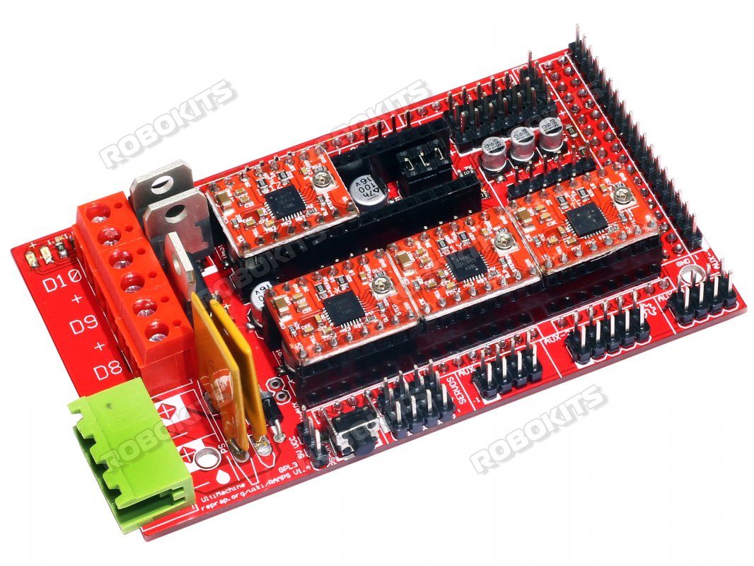
The hardware part is simple enough; you just need a servo signal to control the ESC. A Ramps 1.4 has 4 servo outputs, it's the 3 by 4 pin header at the near edge of the circuit board in the pic below, conveniently marked "SERVOS". Don't connect the 5V from the ESC BEC to the Ramps board, just the signal and ground. The ramps and arduino might not like the supply noise that could potentially be fed back from the ESC, and they each work fine with their separate supplies.


baaa578f3251f854cc4fb8b07e862baa.image.1066x800.jpg


Up front I don't have a lot of experience with the software side, i.e. partly modifying the arduino firmware you specifically are using (Which one is it?) to set up the port, and how to add the start and stop commands to the G-code for the given setup, but I have an electronics engineering background, so it's fairly accesible to me, and there might be a good chance we can find a tutorial or similar on it on the GRBL, repetier or other relevant forum. I also happen to have an arduino Mega and a ramps 1.4 on hand, and i am pretty sure I can find a BL motor and an ESC somewhere, so i might even be able to try it out, given I can find the time.
For example, here's an example of a description of this for Repetier, that came up in a fast google search: https://forum.repetier.com/discussion/2517/using-a-servo

So the basics of it will likely be to first set the configuration of the firmware to have a "servo instance" and to set a physical digital port number on the arduino for this servo instance. Seems simple, but the tricky part is finding out where to do it in the firmware you use. Might have some similarity to the repetier example though; it appears most of the existing CNC firmwares available for the arduino share origins to some degree.
Then it's just a question of finding the right G-code command to operate the set servo port. In the repetier example , the description:
"/* ======== Servos =======
Control the servos with
M340 P<servoId> S<pulseInUS> / ServoID = 0..3 pulseInUs = 500..2500
Servos are controlled by a pulse width normally between 500 and 2500 with 1500ms in center position. 0 turns servo off. "

basically tells us all we need to know. The G-code command "M340 P0 S500" should set the relevant servo port to one extreme(esc stopped in your case), "M340 P0 S2500" to the other(ESC full speed). And if you set the S parameter to a value btw. 500 and 2500, you can set the actual speed. But this is for repetier, it might be different for the firmware you are using.


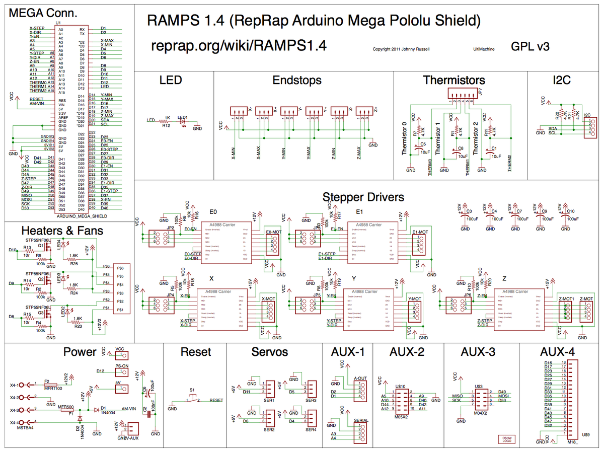
FYI, the 4 servo outputs on the ramps 1.4 are connected to digital ports 4,5,6 and 11 on the arduino.
You can see this in the schematics of the Ramps 1.4 below. For instance the physical servo port SER1 is connected to the D11 port of the arduino.
1200px-RAMPS1.4schematic.png
 
Last edited: