SIRNicolasRemington
New member
Oh I don't know where to begin... This is probably going to be long.
I have never built a quad-copter before and me and my friends decided to take it as a fun project for winter break.
I acquired a 1/8 inch aluminum sheet and my friends designed a frame on solidworks to water jet and CNC Mill at the university.
It was a very promising frame that wasn't too heavy in weight. I believe it was around 0.25kg
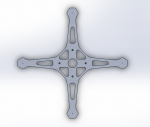 Frame Designed on SolidWorks
 Aluminum Sheet after water jetting
 Frame on CNC Mill prepping for mounting holes
 Post CNC Mill
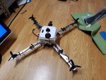 Version One. (It looks so ugly. I know).
Here's where problems starting showing up. My first flight controller was a T-Motor F7 Premium Flight controller. It was a expensive FC and I thought it would pay off. My PDB had a 8pin connector while the Flight Controller had 10. So i opted to use 22awg solid core wire instead. Everything was wired correctly with good solder joints. The problem is that the Battery + and - through hole connectors on the flight controller started shorting. Melting the wire. I thought i could remedy this with some hot glue. It held up until I tested the quad outside and had high throttle. It burned through the hotglue and destroyed the PCB layer, permanently shorting the connectors internally.
Version 2:
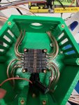
I was afraid of through hole connectors at that point on and opted for a 4 in 1 ESC with a connector and got a Lumenier Lux F7 Ultimate.
I thought my problems were over. I was wrong.
The ribbon cable pinouts for the ESC iFlight SucceX 50A had the group of Motor Serial in a different location that the Lumenier LUX F7. Not to mention the positive and negative were swapped. Luckily I double checked this, otherwise the FC would get hit with a 6S LiPo polarity reversed.
I painstakingly cut and soldered and shrink wrapped every single cable to insure it was correct. Double checking with a multimeter for shorts or incorrect layout.
Everything worked for the time being. Setup the Receiver with iBUS, Dshot600, etc. Used beta flight to check motor position. (It was correct).
It worked. It looked Nice. I designed a 3D printed enclosure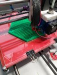
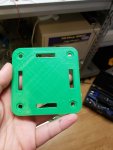 LiPo velcro strap mount.
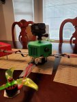
Now for the Ultimate failure. I took it out to test today. VTX worked, clear image. I run Battery voltage from the FC to a Variable voltage regulator set for 8v for the VTX. (I think it runs better and heats up slower).
It arms. Motor spins. It then lifts probably a feet off the ground before motors stop dead.
OCD displays "Calibrate".
I look it up and people say you should turn off the quad and max our your transmitter throttle. Then turn on the quad.
I did that. The calibration disappears. I arm the quad once more and slowly increase the throttle. I increase the throttle to max. It flies up quick and does a flip and crashes. There is no visible damage. It was a mild crash. My antenna and frame probably took most of the hit. Nothing broke loose. Everything inside is mounted on rubber standoffs. I set the quad on the table and test it. Nothing was damaged. It's faulty as it was. I then decide to remove the props to dry run it. After turning it on again. ESC's only beep once. Then random motors start spinning and stopping. Searched it up to be a error code that ESC don't have a signal to FC. I also noticed my VTX went down then too. I took it back to my office to check on the FC. Betaflight no longer detects it. USB only powers up the FC 3.3v LED and it flickers. Multimeter measures it at 0.8v
Everything else on the board still works. 5v, VTX, Bat Voltage, GND. Online forums said to find a 3.3v regulator and replace it. I tested every component on the board with a multimeter and was only able to find one module that reacted. It took in battery voltage twice. One direct and one that comes through another module. A Filter maybe?
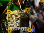
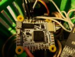 FC: No visible damage. (I took it off its standoffs).
Thanks for reading all the way. I can't identify the problem. Voltage Spikes under load? Lumenier F7 Ultimate accepts up to 8s, I'm using a 6s. No way a spike would exceed that.
I'm new to this and It has been a great learning experience. I just need to know what happened. I really like the Lumenier F7 as it has a barometer too and the overall color scheme is really nice.
I would like to try again, however since I just destroyed $100 in terms of two dead flight controllers. I need help before i venture any further.
Many Thanks,
Henry.
I have never built a quad-copter before and me and my friends decided to take it as a fun project for winter break.
I acquired a 1/8 inch aluminum sheet and my friends designed a frame on solidworks to water jet and CNC Mill at the university.
It was a very promising frame that wasn't too heavy in weight. I believe it was around 0.25kg
 Frame Designed on SolidWorks
 Aluminum Sheet after water jetting
  Frame on CNC Mill prepping for mounting holes
 Post CNC Mill
 Version One. (It looks so ugly. I know).
 Here's where problems starting showing up. My first flight controller was a T-Motor F7 Premium Flight controller. It was a expensive FC and I thought it would pay off. My PDB had a 8pin connector while the Flight Controller had 10. So i opted to use 22awg solid core wire instead. Everything was wired correctly with good solder joints. The problem is that the Battery + and - through hole connectors on the flight controller started shorting. Melting the wire. I thought i could remedy this with some hot glue. It held up until I tested the quad outside and had high throttle. It burned through the hotglue and destroyed the PCB layer, permanently shorting the connectors internally.
Version 2:

I was afraid of through hole connectors at that point on and opted for a 4 in 1 ESC with a connector and got a Lumenier Lux F7 Ultimate.
I thought my problems were over. I was wrong.
The ribbon cable pinouts for the ESC iFlight SucceX 50A had the group of Motor Serial in a different location that the Lumenier LUX F7. Not to mention the positive and negative were swapped. Luckily I double checked this, otherwise the FC would get hit with a 6S LiPo polarity reversed.
I painstakingly cut and soldered and shrink wrapped every single cable to insure it was correct. Double checking with a multimeter for shorts or incorrect layout.
Everything worked for the time being. Setup the Receiver with iBUS, Dshot600, etc. Used beta flight to check motor position. (It was correct).
It worked. It looked Nice. I designed a 3D printed enclosure

 LiPo velcro strap mount.
Now for the Ultimate failure. I took it out to test today. VTX worked, clear image. I run Battery voltage from the FC to a Variable voltage regulator set for 8v for the VTX. (I think it runs better and heats up slower).
It arms. Motor spins. It then lifts probably a feet off the ground before motors stop dead.
OCD displays "Calibrate".
I look it up and people say you should turn off the quad and max our your transmitter throttle. Then turn on the quad.
I did that. The calibration disappears. I arm the quad once more and slowly increase the throttle. I increase the throttle to max. It flies up quick and does a flip and crashes. There is no visible damage. It was a mild crash. My antenna and frame probably took most of the hit. Nothing broke loose. Everything inside is mounted on rubber standoffs. I set the quad on the table and test it. Nothing was damaged. It's faulty as it was. I then decide to remove the props to dry run it. After turning it on again. ESC's only beep once. Then random motors start spinning and stopping. Searched it up to be a error code that ESC don't have a signal to FC. I also noticed my VTX went down then too. I took it back to my office to check on the FC. Betaflight no longer detects it. USB only powers up the FC 3.3v LED and it flickers. Multimeter measures it at 0.8v
Everything else on the board still works. 5v, VTX, Bat Voltage, GND. Online forums said to find a 3.3v regulator and replace it. I tested every component on the board with a multimeter and was only able to find one module that reacted. It took in battery voltage twice. One direct and one that comes through another module. A Filter maybe?

 FC: No visible damage. (I took it off its standoffs).
 Thanks for reading all the way. I can't identify the problem. Voltage Spikes under load? Lumenier F7 Ultimate accepts up to 8s, I'm using a 6s. No way a spike would exceed that.
I'm new to this and It has been a great learning experience. I just need to know what happened. I really like the Lumenier F7 as it has a barometer too and the overall color scheme is really nice.
I would like to try again, however since I just destroyed $100 in terms of two dead flight controllers. I need help before i venture any further.
Many Thanks,
Henry.


