Flying without a vertical stabilizer

telnar1236

Elite member
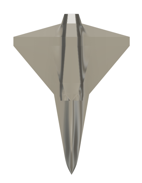
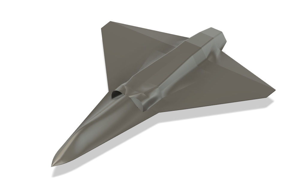
A lot of next generation fighter concepts are tailless, so naturally I've been curious about how reasonable it would be to build an RC version. The short answer is it seems like it will be way easier than I thought. I've been playing around with foam board chuck gliders while I work on some of my modular planes, and the trick seems to be careful shaping of the fuselage and wing that allows the fuselage to keep the plane directionally stable. Not sure how far I'll pursue developing this, but it would be kind of cool to have a tailless NGAD with thrust vectoring eventually. For now, I'm contenting myself with trying to print a 50mm EDF. If that works, I might pursue this more once I finish some current projects.
1716684638865.png

1716684665403.png

1716684691066.png

1716684715898.png

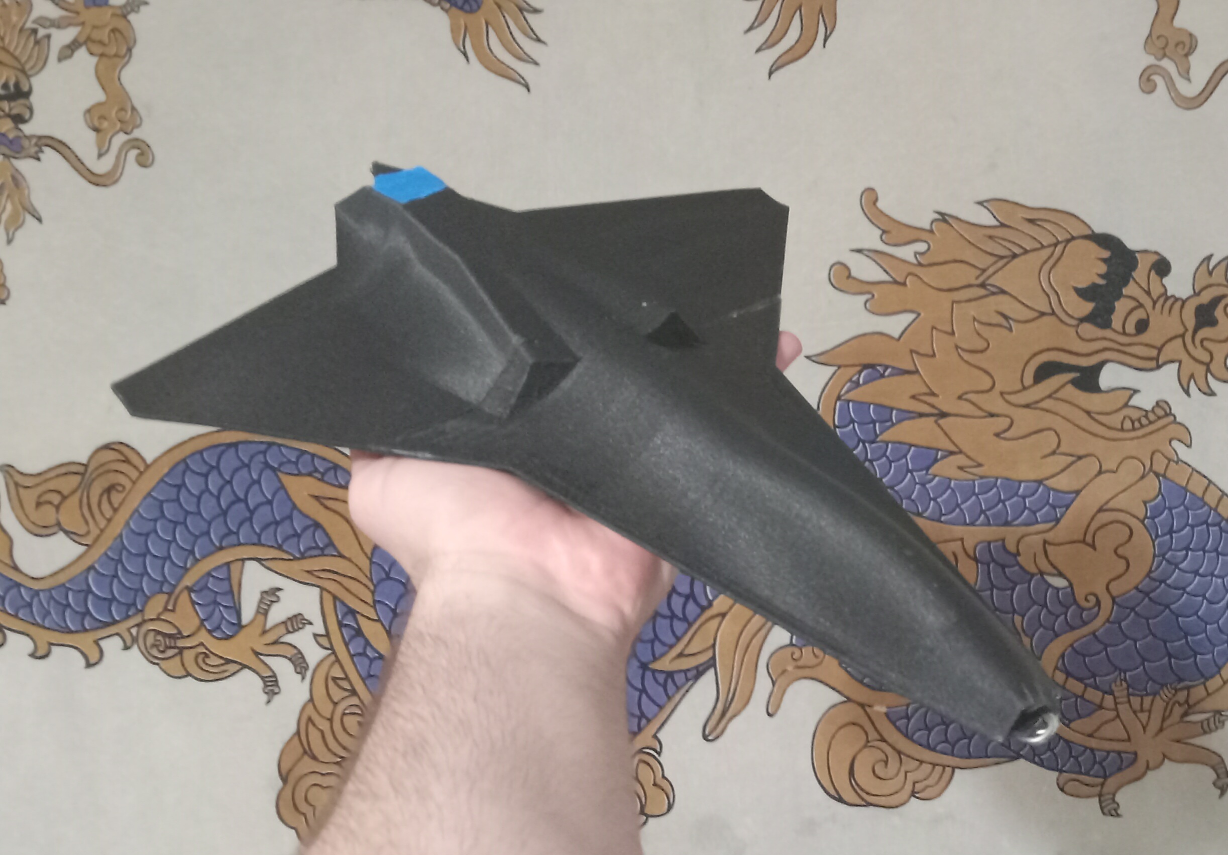
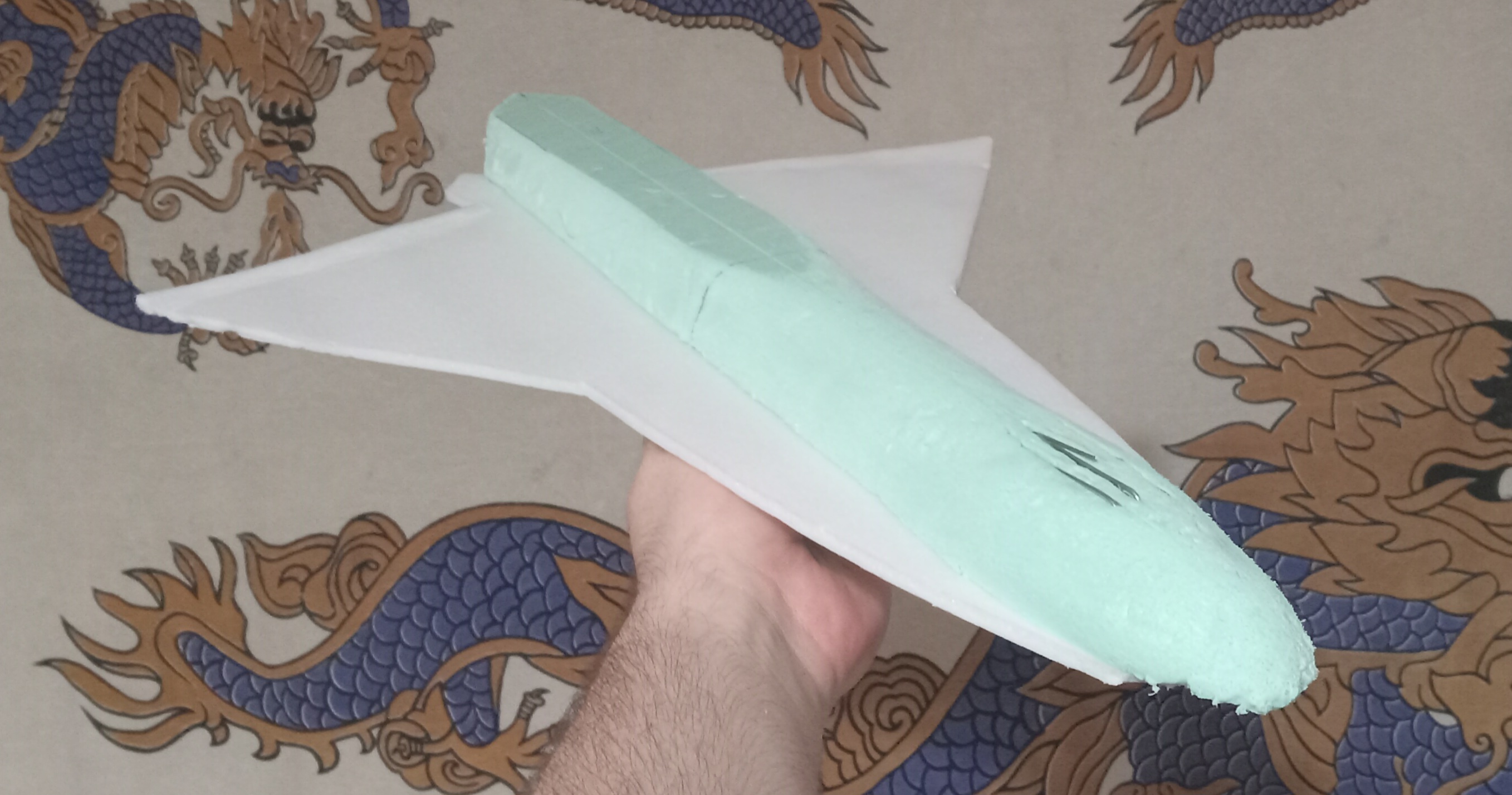
So far, I have printed a LW PLA chuck glider and built a couple foam board chuck gliders. They are all shockingly stable, to my great surprise. The foam board glider pictured here can actually be thrown at 90 degrees yaw and will self-correct if it has enough height. The 3D printed glider is a bit harder to test because of its higher wing loading but shows similar stability. Both are a bit beat up from testing, and I had to break the nose of the 3D printed version to add paper clips to get it to balance.
20240525_205739.jpg

20240525_205836.jpg
 

telnar1236

Elite member
The big goal of this project is to make a plane that looks like a next gen stealth fighter. Having winglets would definitely help stability but would sort of go against the idea. To be perfectly honest, I'm still trying to figure out why it is as stable as it seems to be, but I'm currently thinking it's a combination of the shape of the fuselage and the shape of the wing. My original thought was that by having the sharply angled edges on the back and the smooth cross-section on the front, I could make the back increase in drag far faster than the front as sideslip angle increases. That's definitely happening, but from my glide tests, more seems to be going on too. The wing without any fuselage is also inherently somewhat stable, though nowhere near what it is with the fuselage. My current thinking is that the combination of the sweep of the wing and the vortices generated by the extremely highly swept inboard leading-edge result in exceptionally high lateral stability. Then when the fuselage is added in, it prevents the vortex on the advancing wing from spilling over onto the retreating wing, further increasing lateral stability and enhancing the directionally stability the fuselage already has on its own by strengthening the low-pressure region on the retreating side. I've somewhat been able to confirm this with tests where I strategically changed the shape of the wing on the chuck glider cutting out the inboard trailing edge to make both the leading and trailing edges swept (and adjusting the CG accordingly), which would disrupt the vortex along the aft part of the fuselage, and it did result in a significant loss of stability. However, that airplane was stable upside down with the fuselage in the airstream (it only had fuselage on the top of the wing) which showed the fuselage also has some inherent directional stability on its own.
 

JasonK

Participation Award Recipient
Is the yaw center of pressure [CP] behind the CG? [from model rocketry, you can find the CP by cutting out a profile image of the object then finding the balance point of that profile, that should be roughly the CP - if your GC is far enough forward, the fuselage itself might be getting you a needed vertical stabilization]

my second thought could just be drag variations off the wings/etc.
 

Piotrsko

Master member
If you don't mind the need to fly straight, and can tolerate yaw, you don't need a controlling surface. A flat sheet of foamboard done as a flying wing flies well enough although sometimes sideways. See also B2 and most of Jack Northrups flying wings but that's structure and or surface yaw modulaton.
 

telnar1236

Elite member
Is the yaw center of pressure [CP] behind the CG? [from model rocketry, you can find the CP by cutting out a profile image of the object then finding the balance point of that profile, that should be roughly the CP - if your GC is far enough forward, the fuselage itself might be getting you a needed vertical stabilization]

my second thought could just be drag variations off the wings/etc.
That was one of the first thing I tried to eliminate in tests of the fuselage shape, the profile of the fuselage actually has a tiny bit more area ahead of the CG than behind it at the best flying CG. The drag variations are a good thought though, although I'll need to figure out a way to test them.
 

telnar1236

Elite member
If you don't mind the need to fly straight, and can tolerate yaw, you don't need a controlling surface. A flat sheet of foamboard done as a flying wing flies well enough although sometimes sideways. See also B2 and most of Jack Northrups flying wings but that's structure and or surface yaw modulaton.
What's interesting about this profile is that it actually seems to recover from high sideslip angles faster than some more conventional designs. Some of my tests involved tossing the glider at 90 degrees, and it pretty much always recovered. For comparison a micro spitfire I have recovered very fast with minimal oscillation, while a micro cub didn't recover at all a fair bit of the time (surprisingly). Swept flying wings have some inherent stability due to the wing sweep, so that may also be what's going on here, but with the very low aspect geometry, I think more must be going on.
 

Piotrsko

Master member
Sounds more like you have static stability ironed out with the cg and COP in the proper places and spacing. Other than @JasonK s cardboard profile I don't know how to determine COP easily.

Otoh, keep it up. I find your posts very educational even for an old, jaded curmudgeon.
 

L Edge

Master member
In designing and solving the X-47B 8 years ago, I took an approach of solving the rudderless or vertical stab problems by attacking the yaw/roll issue without any gyro or FC.

Summarizing what I did to get mine to work:
1) Put a 1-2 degree of dihedral into the delta wing.
2)Took a 64mm EDF thrust vectoring unit and pivot offset of the control pin/slot 45 degrees for proper setup of yaw for the thrust vectoring unit.
3) Need only 2 servos which gives the set up elevons. Upper servo arm control go to physical surfaces. Deflection is about 3/8 inch.
4) On each servo arm, installed guided wires in lower hole which ran to each thrust vectoring unit so when aileron/elevator servo moves, the physical surfaces move as well as the thrust vectoring unit in the right direction so yaw control is generated and controlled. Did a lot of fine tuning of the thrust vectoring deflection to get stability of flight from takeoff to landing.

Here is what it looks like.

.
IMG_1342.JPG

IMG_1341 (1).JPG


After 8 years, still fly this model a couple of times a year. It is super sensitive in roll and yaw. Too bad my field is so small. Houses all around, don't want to crash into their property and lose my field. Floats like a butterfly.


What is even worse, is planes like the B2, where the inlet and exhaust ducting due to stealth, causes a lot of problems that differential thrust can't solve.
 

telnar1236

Elite member
The plane is now mostly printed (just one more fuselage piece and the elevons left).
20240529_222839.jpg

I also did a bit more testing to see if I could nail down what's keeping the plane stable. All four configurations on the left are stable, while the two on the right are not (as expected - I made them as controls to make sure that any foam board shape I made would not be stable). Here are the notes of interest:
  1. The most stable planforms were the two at the bottom left (a pure delta and the cranked arrow delta I'm using for the powered model). Of the two the cranked arrow shape was the more stable.
  2. All the delta plan form shapes were stable. The top left design with where the portion of the wing at the back has no sweep was the least stable.
  3. There was only a small improvement going to a cranked arrow delta that may be attributable to slight differences in balance. The vortex channeled by the corner between the two delta wing sections has a minimal impact on stability.
  4. Neither of the forward swept wing planforms was at all stable showing that some degree of sweep is needed for stability. Not pictured, a foam board square had enough stability to fly, but required a very far forward CG in comparison to the deltas and was barely stable.
  5. To test if it was simply a case of having more side profile area aft of the CG, I added a vertical profile to the two most stable wings (at the bottom left) with area entirely forward of the CG. It negatively impacted the stability, but only by a bit. Therefore, I can pretty confidently rule out side profile as a significant contributor to these specific designs.
I'm thinking it's probably a combination of the drag from the flat leading edge of the wing, the wing sweep (lateral stability), and a rapid increase in induced drag on the advancing wing that's keeping the planes stable. My thoughts about the leading-edge vortices helping are at best responsible for barely any stability as shown by the stability of the plain delta wings, and the side profile of the fuselage is the same, at least for the gliders I tested previously. The changing front profile of the fuselage did seem to help in earlier tests and increased stability, but I didn't try and test that with this series of gliders.
 

telnar1236

Elite member
In designing and solving the X-47B 8 years ago, I took an approach of solving the rudderless or vertical stab problems by attacking the yaw/roll issue without any gyro or FC.

Summarizing what I did to get mine to work:
1) Put a 1-2 degree of dihedral into the delta wing.
2)Took a 64mm EDF thrust vectoring unit and pivot offset of the control pin/slot 45 degrees for proper setup of yaw for the thrust vectoring unit.
3) Need only 2 servos which gives the set up elevons. Upper servo arm control go to physical surfaces. Deflection is about 3/8 inch.
4) On each servo arm, installed guided wires in lower hole which ran to each thrust vectoring unit so when aileron/elevator servo moves, the physical surfaces move as well as the thrust vectoring unit in the right direction so yaw control is generated and controlled. Did a lot of fine tuning of the thrust vectoring deflection to get stability of flight from takeoff to landing.

Here is what it looks like.

. View attachment 243990
View attachment 243991

After 8 years, still fly this model a couple of times a year. It is super sensitive in roll and yaw. Too bad my field is so small. Houses all around, don't want to crash into their property and lose my field. Floats like a butterfly.


What is even worse, is planes like the B2, where the inlet and exhaust ducting due to stealth, causes a lot of problems that differential thrust can't solve.
That's an impressive design. Does it seem to have any stability without the thrust vectoring or is that absolutely necessary for it to fly?
 

L Edge

Master member
First started with a fixed rudder, then cut segments off it and then flew. Reached a point in the process where it lost the stability as I trimmed. Then built a model with TV to get it to work. Yes, absolutely necessary.

You think that is bad, been exploring the stealth shape NYGAD's. With EDF exhaust shapes of weird design, exhaust flow causes uneven forces that need to be solved for stability flight.

Hope yours work.
 

Piotrsko

Master member
Inquiring kinds want to know: is the cg actually in front of the COP on the stable ones, and what alchemy did you use to determine that condition? This has perplexed me for the last 60 years after I built a delta winged rocket that boosted straight as can be but tumbled slowly back down every which way.
 

L Edge

Master member
Inquiring kinds want to know: is the cg actually in front of the COP on the stable ones, and what alchemy did you use to determine that condition? This has perplexed me for the last 60 years after I built a delta winged rocket that boosted straight as can be but tumbled slowly back down every which way.

Didn't you know, I am a "SkunkWorks" facility. I design things that don't exist. I just look at things differently(my alchemy). Next release I'll show will be my designed fighter wing that morphs(swings) from perpendicular to aft like - 45 degrees (Tomcat) to the X-29 forward swing of+33 degrees in flight. Far as I know, no one else has it, not even NASA. Again, no battery movement in flight, no FC or gyro.
Think I know your answer to the rocket. Need to do my research.

Since this is Telnar's thread, will follow on what happens with his approach. Only reason I showed my video is if you don't show it, didn't happen.
 

telnar1236

Elite member
Inquiring kinds want to know: is the cg actually in front of the COP on the stable ones, and what alchemy did you use to determine that condition? This has perplexed me for the last 60 years after I built a delta winged rocket that boosted straight as can be but tumbled slowly back down every which way.
So, there's actually a lot to unpack in the answer to this question. First, stability can broadly be broken into longitudinal (pitch) stability and lateral-directional (roll-yaw) stability. Second, I've been using COP somewhat loosely. The center of pressure is the location where the lift force acts through and shifts with angle of attack. For aerodynamic stability (pitch and yaw at least), we're actually more concerned with the aerodynamic center which is the point about which moment stays constant with angle of attack. For symmetrical airfoils these are at the same location which is 1/4 the mean chord, and in general, the AC and COP are at about the same location, most of the time. If the CG is ahead of the aerodynamic center, the airplane is positively stable regardless of the center of pressure (though for all intents and purposes the center of pressure will also be behind the CG).
With those definitions out of the way, all of these chuck gliders are stable in the pitch direction. I added paper clips until they were and then bent the trailing edge up until they were trimmed for gliding flight. In other words, those test foam board chuck gliders were essentially just me using the cutout profile method. The CG is ahead of both the aerodynamic center and center of pressure in the pitch direction (as determined by trial and error).
For the yaw direction, I made sure that there was only vertical material ahead of the CG (tested by balancing it on my fingers). Since the pressure acts on the cross-section of the plane, only having cross-sectional area ahead of the CG eliminated having a rearward COP driving a rearward AC (the aerodynamic center must be behind the CG since they were stable in my tests despite the forward COP). Instead, drag effects on the wings must have been driving the directional stability, somehow. It's also worth noting that high roll stability can, somewhat, overcome poor yaw stability since as soon as the plane yaws, it banks into the yaw, preventing it from yawing too far.
All of this also only applies before stall. As soon as the wing starts to stall, the COP and aerodynamic center can shift dramatically. For the particular planform I'm building my plane with, the inboard delta wing with the highly swept leading edge will generate a vortex that keeps flow attached, both to it and the inboard section of the less swept part of the wing, which shifts the COP and aerodynamic center forwards as the outboard section stalls first. As I've alluded to previously, the COP in the yaw direction is at a very different location from the aerodynamic center (I think), and will rapidly shift backwards as sideslip increases, while the aerodynamic center should stay about the same up to a pretty high sideslip angle.
Long story short, chuck gliders are the easiest way to make a good COP and CG determination, as all of you have already been saying. There is a ton of math, but by the time I could have worked through it for one configuration of the chuck gliders, I could have built and tested all of them. And for the more complicated 3D shape of the RC version, in the yaw direction especially, the only workable approach would be computer simulation. A good rule of thumb is that the AC is at about 25% of the mean aerodynamic chord for most wing shapes.
 
Last edited:

telnar1236

Elite member
The 50mm EDF version is now totally ready to fly! I'll test it as soon as weather and time permit. It weighs in at around 700 g ready to fly and can balance on either a 1300 mAh or 1500 mAh 3s pack. I think the likelihood of it being fully controllable throughout a whole flight is only about 50%, but all the chuck glider tests were promising, so hopefully it works.
20240601_011004.jpg
 

telnar1236

Elite member
Well... to put it mildly, the design needs some work. It is just about possible to keep it in the air, but any wind gusts or maneuvers tend to make it want to spiral into the ground. My longest flight was about 15 seconds, though on a less windy day I think I could have probably kept it in the air for a few minutes. Unrelated to the stability of the airframe, it was also pretty underpowered which made launching it difficult. But the airframe is very durable and it took several hard impacts with the ground without any damage, although eventually the nose cracked and a wing ended up falling off.
20240602_115413.jpg

I think my next step will be to make a few foamboard profile gliders with servos and bungee launch them to see if I can get the controls a bit more manageable. I'll probably eventually just go with a gyro in the yaw axis. Probably should have taken this as an intermediate step the first time around, but I got impatient.
 

telnar1236

Elite member
With the lack of success of the first version, I decided to break out the simulations. Here are some stability results from XFLR5. The X axis is the sideslip angle and the Y axis is Cn (yaw moment coefficient). The steeper the line is, the more stable the aircraft. It confirms that the wing planform is inherently stable, but only just. The gray line is the chuck gliders and the pink line (with the lowest slope) is the version I tried flying today. By playing around and having parts of the wing with wash in and the tips of the wings with wash out to achieve bell shaped (ish) span loading, I was able to roughly double the stability (blue line) and adding 5 degrees of anhedral roughly doubles it again (navy blue line). However, even this is only about a tenth of what I would get from a conventional vertical stabilizer (the nearly vertical orange line). All of these analyses were performed at 2 degrees angle of attack.
1717380074999.png

What I found most interesting from this was that adding dihedral actually hurt the directional stability instead of helping it. I modeled in 3 degrees dihedral in the EDF version that was not present in the chuck gliders which may help explain the worse stability I observed. I knew that messing with the lift distribution by adding in the twist to the wing would have this effect but didn't bother with it in this version since it would have made designing it a lot slower and the chuck gliders were so promising.

Another interesting thing to note is that the inherent stability becomes worse at low Reynolds numbers (low speeds). This suggests that instead of hand-launching I might have had more luck with something like a bungee launch which would have gotten the plane right into higher speed flight. The navy blue and red lines are at 40 mph and 80 mph respectively, well into turbulent flow, and pretty much overlap, while the green line is the extreme case of 5 mph (less than stall speed but it shows the effect more clearly).
1717380216737.png

The good news is I now know why the plane had the issues it did, why it didn't match the performance of the chuck gliders, and next steps to get it to fly better.