FT Slow Stick S250

Taildragger

Legendary member
Not a bad bush plane tbh
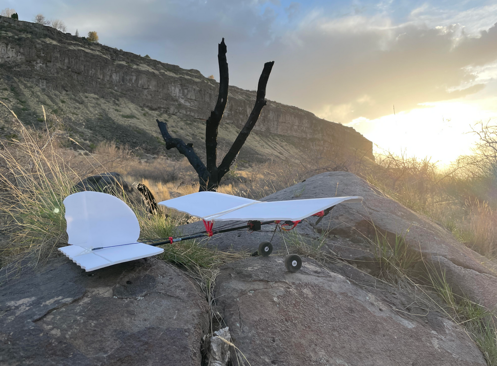
1682956111585.png
 

alan0043

Well-known member
Hi Everyone,

I have most of my parts printed out but having a problem with the servo holder. One of loops on the end of the servo holder wants to break in have. Has this happened to you ? I see Hoomi has a different idea to hold his servos. I don't know how to beef up the loops on the servo holder. I also don't know how to use TinkerCad.
 

RonM

New member
Can we get a hold of FT and see if they can add some details to the plans.... like shaft length, where to put the wing supports on the shaft, etc
I have arrow shafts, and some regular carbon shafts (with same dia.) that I ordered way back when.

Im doing the 3ch build as we speak

Edit: Also what dihedral? How to form wing under camber curve.... I know they are free plans but all they really gave ya was the basic wing and tail shapes and some STL files (that need modded as the rubber bands wont stay on the little nubs) 🤔🤦‍♂️🤷‍♂️
Hello, I compared and scaled the placement of the parts,
also the camber, from the vid. I glued the wing to the mounts.
the maiden flight was very tail heavy, and have since added 1 oz.
to the nose. Should fly better.
 

Hoomi

Master member
Hi Everyone,

I have most of my parts printed out but having a problem with the servo holder. One of loops on the end of the servo holder wants to break in have. Has this happened to you ? I see Hoomi has a different idea to hold his servos. I don't know how to beef up the loops on the servo holder. I also don't know how to use TinkerCad.
On mine, the PLA would snap when I tried to remove the supports from the print process. I finally decided if I couldn't manage to even get it cleaned up to install onto the plane, I was probably best not trusting it to hold up in flight. The servos are held into place in typical FT fashion, using hot glue. If I were making another and repeated this modification, I think I would make the servo box a bit longer, so I could move the tail surface servos farther back on the plane, and shorten the push rods for them. As it is, I used two of the wire guides to help make sure I wouldn't have problems with the rods flexing instead of activating the surfaces.

I also had a problem on the original printing of the parts, that the hole for the arrow shaft was just slightly too small for the arrow that I bought. I was trying to balance between small diameter on the arrow shaft, and overall length. The smaller diameter arrows were also several inches shorter. What I finally ended up doing was making a guess, and using the program that came with my 3D printer to resize the part. I used the wire guide, as it's the smallest part, and therefore, the least amount of time and PLA to do an experimental print. For my arrow shaft, I started with 105%. That was large enough to fit the arrow, though still a bit snug, so I printed the rest of the parts at 106%, and that worked fine. Even for the motor mount, the upsizing allowed it to slide over the arrow, but the hole spacing for the motor screws was still close enough to not give any problem in mounting the motor.

For the motor mount and tail mount, I used medium cure epoxy, which gave me about 10 minutes for getting the alignment where I wanted it. The wing mounts I got into the position for the best CG, and the best level alignment with the tail surfaces, and then used CA to secure those. The foamboard for my servo box is hot glued into shape, and then glued to the front wing mount. For the back of the servo box, I used the discarded front wing mount that had a bit too small a hole to slide over the arrow shaft. I reamed out the hole enough to allow it to fit, but didn't want to do that for a part that was as critical as the actual wing mount. The wing is epoxied to both the front and rear wing mounts, as I wasn't worried about having it removable, especially with the aileron connecting rods. The rubber bands add a little extra security to the wing mounting, but I suspect I could probably fly it without the rubber bands.

My other mod was adding the bamboo skewer supports between the horizontal and vertical stabilizers. It probably doesn't really need them, but I figured it wouldn't hurt anything. I wasn't as worried about overall weight at the FT crew was while designing it, since I pretty much only fly at our club field, so the FAA weight restrictions aren't as much of a concern.
 

RickyG

Member
I so wanted to maiden mine this evening, but it is just too windy...

FT SUS.png


I got some Dubro 3inch wheels and printed my own hubs, they are 2 grams lighter, so not a big weight savings, but I was able to design it so that the axle hole fit the metal rods I used. I also redesigned the front wing mount as I seem to fiddle with the rubber bands too much. I took a Sig #67 and cut it in half to make two thinner bands and used those. I lengthened the catches for the rubber bands so that they have to be stretched to fit in there. That way they stay in place while I try and attach them to the rear (I also lengthened those as well)

wing holder wheel.png


The tail skid using a zip tie is genius! I did that as well.

tail skid.png


Ricky
 

Hoomi

Master member
Nice! Your tail surfaces look more like the Horizon Slow Stick. Looking forward to the Maiden Report!
 

tomlogan1

Elite member
I put mine up for her first three flights this morning. The first and third flights were flown using 3S 850 mAh batteries, with the Matecam 808 mounted at the back of the wing to offset the additional weight, while the second flight was flown using the specified 2S 800 mAh battery. With the 2S battery, she balances almost perfectly level at the specified CG point from the plans. With the 3S batteries and the Matecam, she balances just a bit nose down. I'm flying mine 4 channel, and she's among the easiest landing planes I've flown. The nylon zip-tie tail skid worked great, and while ground steering with the rudder isn't as precise or responsive as a steerable tail wheel, she was manageable. On 2S, she was not able to pull a smooth vertical loop from level flight, but rather flopped over backwards before hitting achieving full inverted flight at the top, making more of a teardrop shaped loop. On 3S, she pulled a smooth, circular loop from level flight. Roll rate with my ailerons is decent. She's not a 3D stunt plane, but she'll handle some simple aerobatics. I didn't attempt inverted flight.

On the maiden flight portion of the video, I cut out most of the eastbound portions of the flight, as the sun was low enough to pretty much wash out the view on the camera. The takeoff and landing portions show what I mean pretty clearly.

The only issue I had during the flight, was that the checkerboard tape on the tail starting peeling back. I've secured it with some clear tape folded over the leading edge.

Excellent very nice landing.
 

CappyAmeric

Elite member
I used an original FT A motor so I only tried 2s, so it was VERY slow. I would love to try it with a 2206 quad motor and may do that later. Only one pack because the PLA on the motor pod expands just enough with motor heat to allow the hex screws holding the motor to pull through and letting the motor detach. Fortunately, I heard it happen and went to idle to avoid twisting the motor wires and damaging anything. I think a little E6000 in the screw holes on the motor mount may help in the future.

IMG_6412.jpeg
 

AIRFORGE

Make It Fly!
Moderator
I waited until it was pretty much dead calm (in between rain showers here) flew fine. I needed quite a bit of left rudder and the "maximum trim reached" was for my elevator. I put in some 'reflex' because I thought for sure it would need some up trim, but I was wrong.


Ricky
Floaty and slow! (y)
What is the length of your arrow?
 

RickyG

Member
Floaty and slow! (y)
What is the length of your arrow?

My arrow is 32" flying conservatively, I could probably easily get 6 or 7 minutes out of that 2S 850mAh pack. I baby my batteries and land at 50%. After 4 minutes, I still had 3.9v on each cell.

I also designed this little wheel collar I printed in TPU. It's 5mmx5mm with a 1mm hole. I made a cone at the top with 2mm hole so I could get the wire started.

wheel stop.png


Ricky