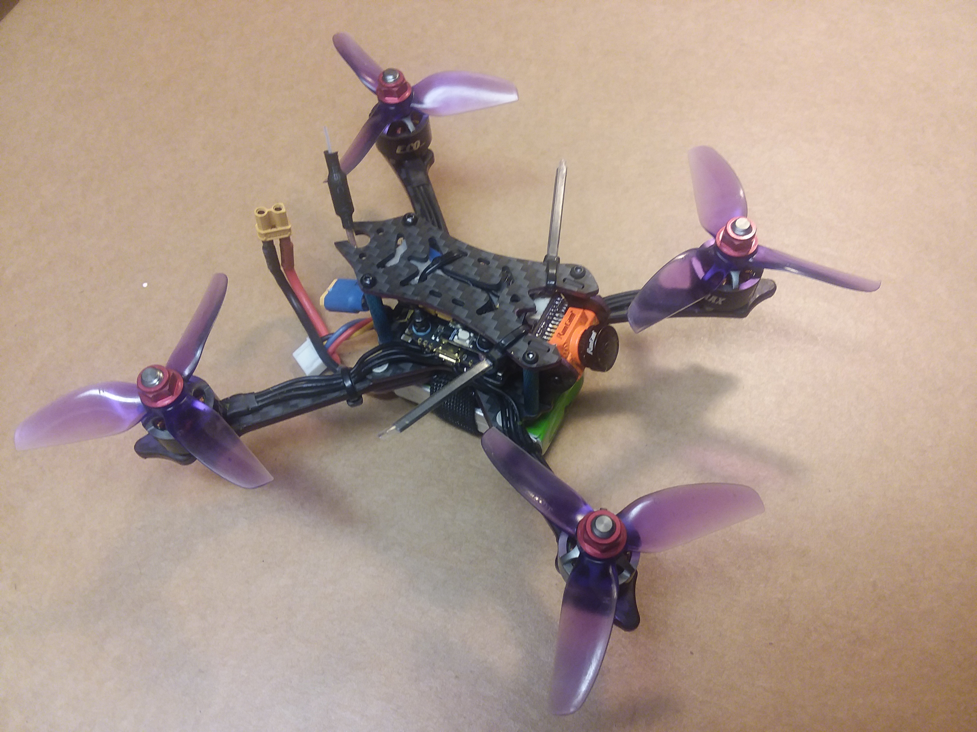
Presenting the Oberon OB-1 3 inch quad evolution.

PsyBorg

Wake up! Time to fly!
Ok the back story for this build is a response to @Mid7night's son Oberon learning to fly his first quad fpv. There were several videos after he was gifted a tiny hawk. As he was learning they would head out to various places to fly serval aircraft from fixed wing to multi rotor.

One particular flight they were both in the air at the same time and somehow the baby hawk went down out in the desert they were flying in. After a long search and several return trips they decided the quad was lost.

This was about the time I usually do my yearly build for myself and was planning on doing a sub 250g build out of depression over the regulation and dismantling of our hobby. I wanted to see if it would be a suitable replacement for my 5 inchers I love ripping around when the time comes to retire or sell them off. I decided I would instead build it for Oberon so he did not have to wait long and lose his progress flying.

So planned the build ordered and gathered the parts and started the build. Not a hard effort by any means as I have built many quads in the last 6 years and have my method worked out pretty good. So here in this post I will show you how I took this..
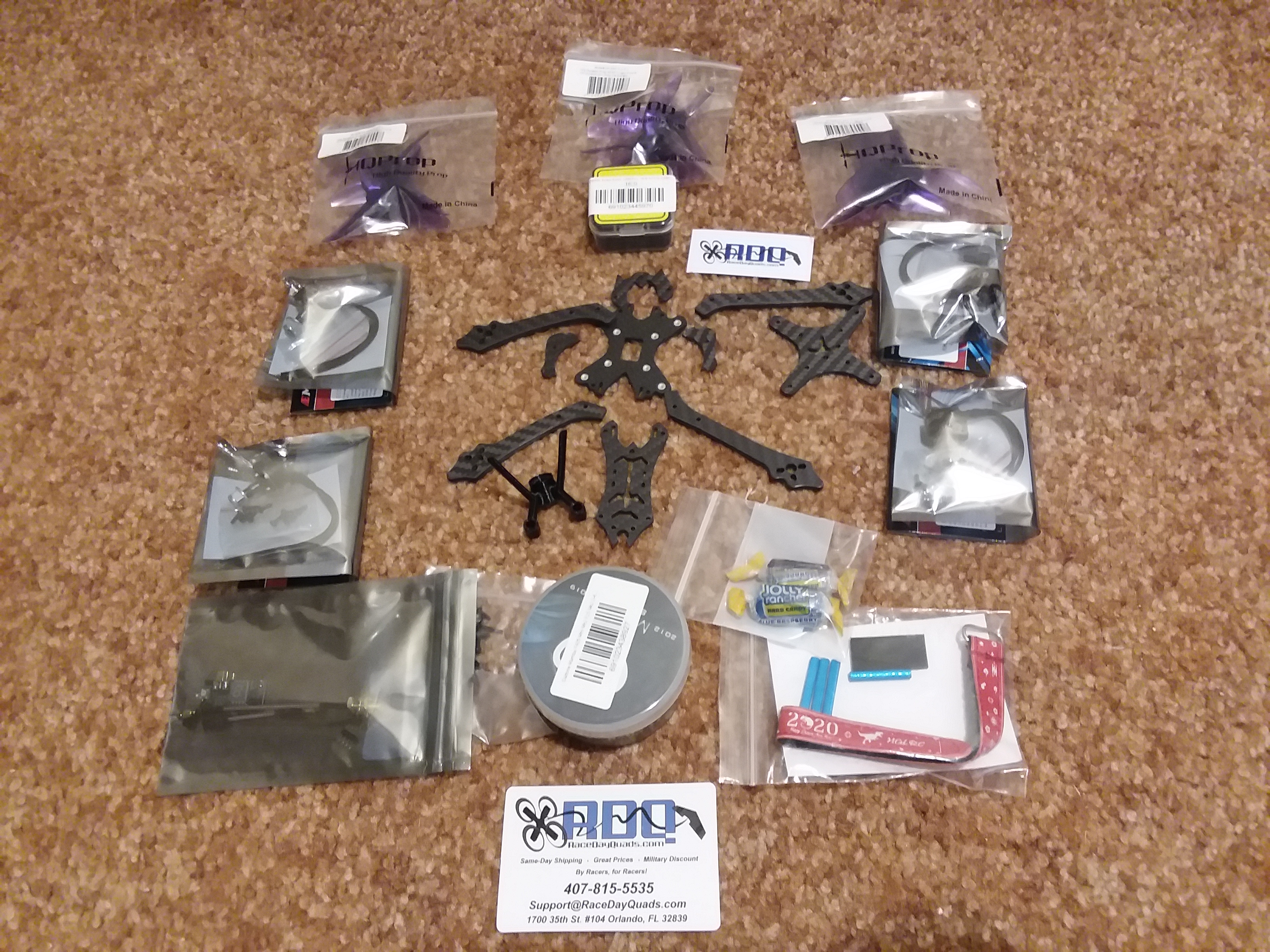
20200523_162231.jpg


and made this

20200528_025856.jpg


In later posts I will go on to show the radio set up, the flight controller settings and all the other stuff I do that others do not do to make my quads more versatile and not pigeon holed into one category now that I have learned most all of Betaflights ins and outs.

So first thing after inventorying all the parts to make sure it is all present and ready to go I do a quick mock up of the frame so I am familiar with how it goes together and get to see how much room I have to mount things. The main reason to mock it up though is to make sure all the parts are in fact present and that all the holes are drilled and align properly. Nothing more frustrating then doing all the prep work for a build only to find you can not mount something because a hole is missing or does not line up at all. You lose the ability to send it back once you mess with it.
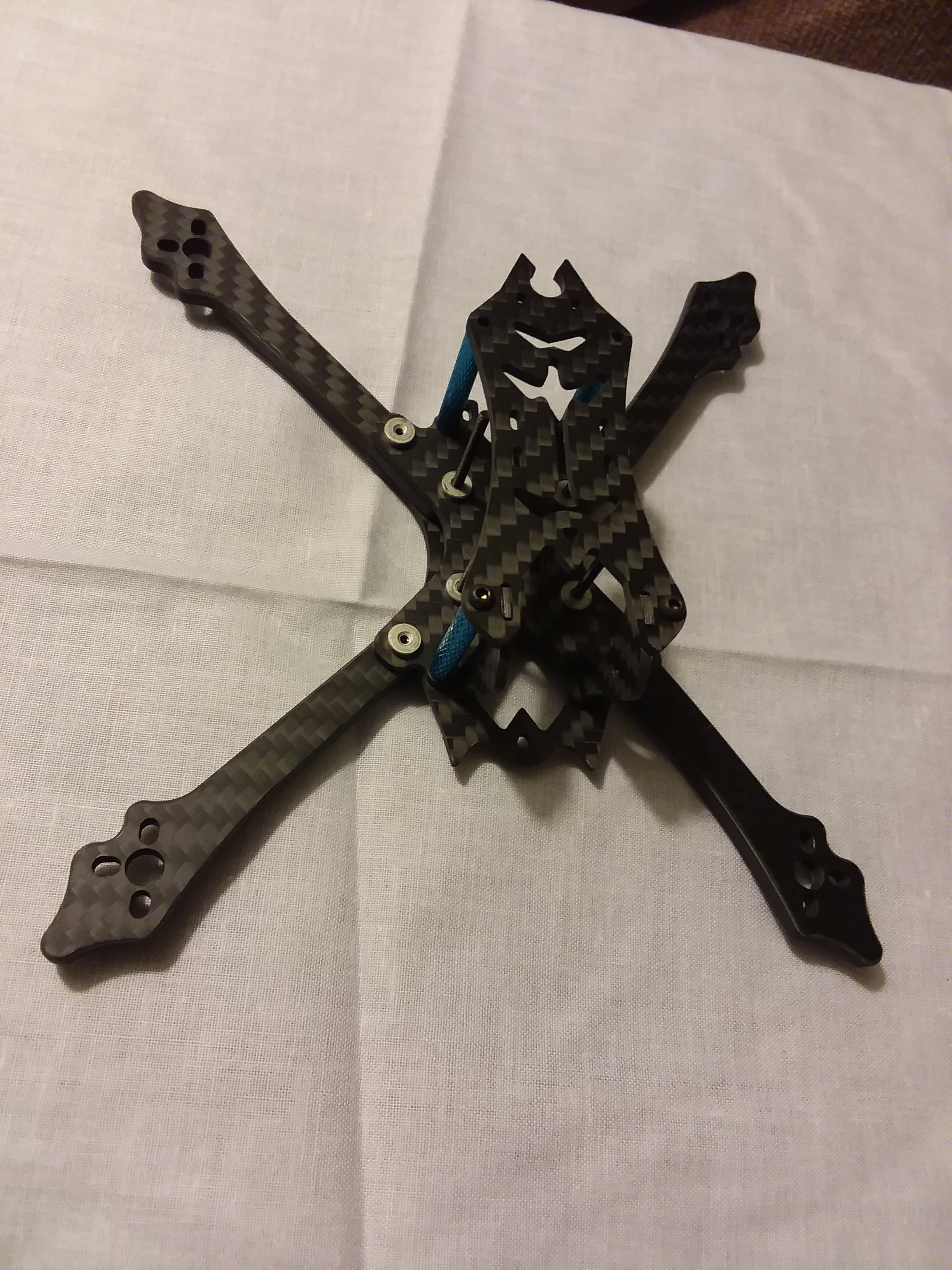
20200523_165847.jpg


Looks good so on with the prep.

First thing I do is wash it off with warm soapy water and rinse and dry it good. This gets all the powdery stuff used to release the carbon from the manufacturing process as well as cleans any residual carbon dust and splinters. Once dry I look over each part and feel for sharp edges. Some frames are well prepped with chamfers and light sanding others are untouched and extremely sharp. This one had respectable edge work but still required a touch up in some spots with a diamond file.

If you have to do this on your frames do it under running water or in a tub of water as carbon dust is deadly. Rubber gloves is also a must as carbon splinters get infected super fast and are quite painful when in your finger tips that are constantly squeezing things.

Once all the edges are smooth I rewash any residual dust or water spots after filing. Once dry I take a small tube of Krazy glue gel and coat all the exposed sides / edges of the carbon on every piece where you can see the layers. Once dry I inspect to make sure there are no exposed areas or places that need a light sanding due to bubbles or drips. This is usually not an issue if I take my time. Here is the link to how I prep frames from a 5 inch build I did last year.


Once the edges are dry I decide what colors I want to paint the arms and plates. For this build I went with Testors Purple Metallic Flake for the edges of all the plates and Red Metallic Flake which when used over black carbon and clear glue looks more like Blood Red. I think the contrast between the two colors is awesome.
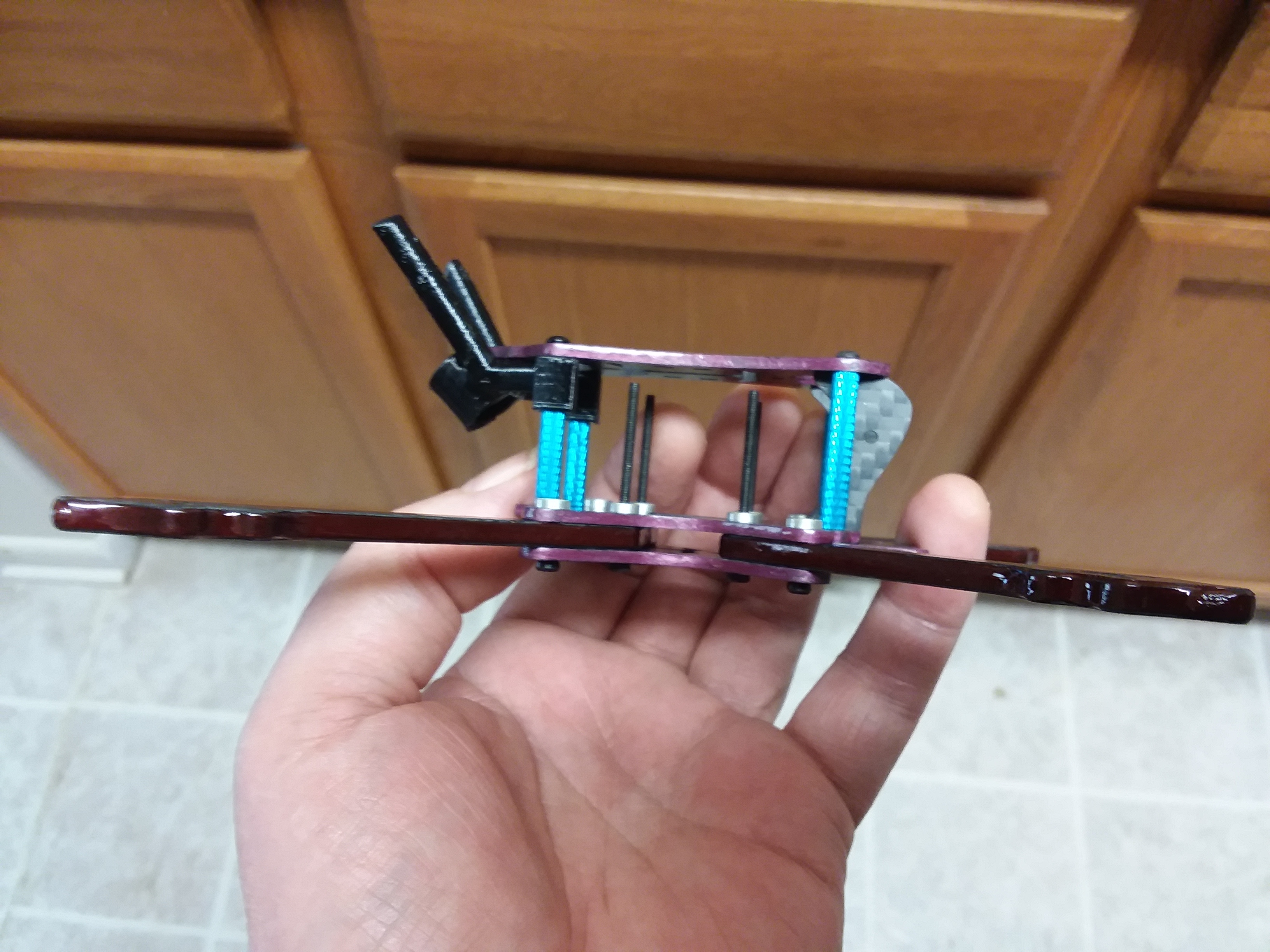
20200524_073704.jpg


And to finish the series out this is the final iteration of this build. All up with a 850mah 4s pack is 253g and with a 650 mah pack will easily be below the 250g mark.

the parts list as finished is:

HGLRC 3" Arrow frame.
Diatone mamba F405 v2 stack with 25a esc
Emax ECO 1407 3300kv motors
Babyhawk race pro 2 VTX
Runcam Pheonix 2 camera
Axii stubby FPV antenna
and finally an Frsky r Xsr receiver.
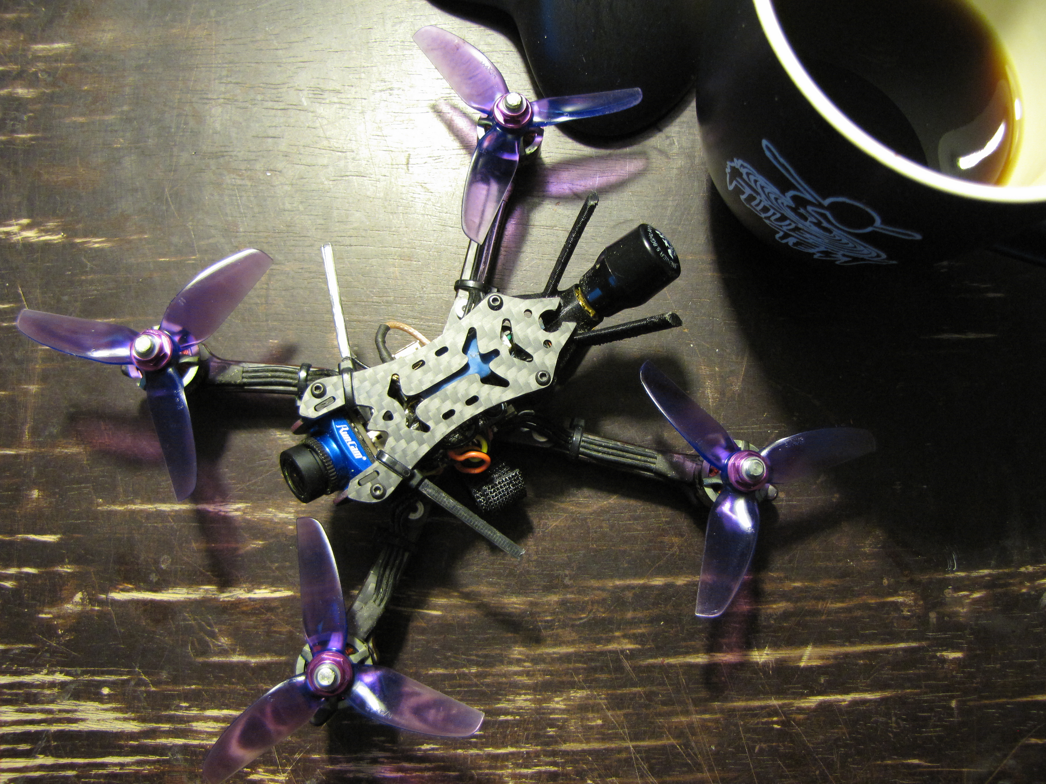
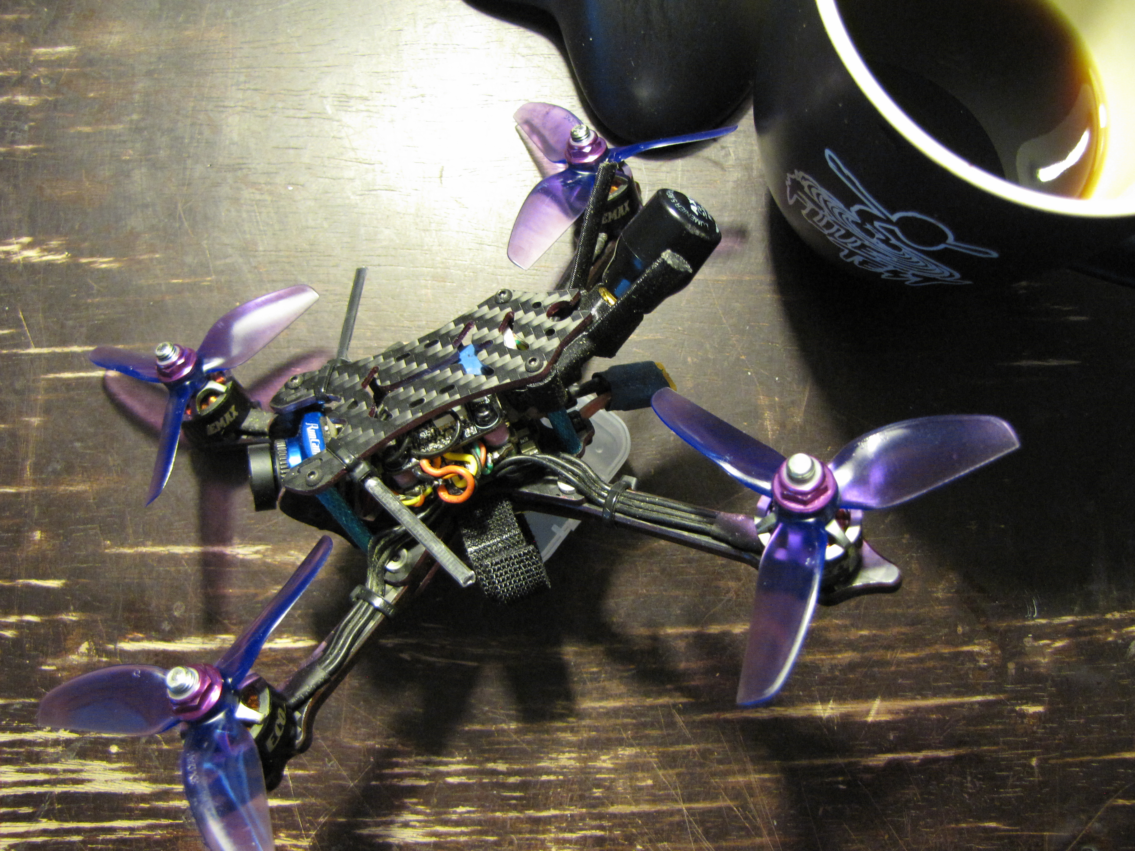
IMG_1064.JPG


IMG_1065.JPG
 
Last edited:

PsyBorg

Wake up! Time to fly!
Ok on to the build stuffs.

First and obvious is to plug the fc into the computer to make sure it works as well as to flash it to current firmware. I'm not going into detail here as there are a bajillion videos and walk throughs how to do this. I will however answer questions later should someone be struggling with it.

The first step in the build again is to mock up where everything will be located. To do this I set the obvious components where
they need to go and begin the task of locating VTX gear, receiver, and cameras. This is important because you need a plan for where the birds nest of wires will be routed to avoid things like signal injection, wear from rubbing, ease of disassembly for cleaning or parts replacement from damage.

Being this is such a small build I knew it was going to be tight getting it all stuffed into the frame and protected. After having a look and some simple thought I had a plan where and how it would all fit and be functional. The first thing that goes on is the esc. During the mock up I saw the four bolts for the stack were also part of the frame structure and passed through press nuts. Obviously you should not just set electronic parts on structural let a lone conducting surfaces that could wear or cause damage by shorting something out.

Looking thru the pile of parts I found there were super tiny silicone "o" rings supplied with the esc. I nearly threw them out as they were near invisible when in the plastic bag with the wires and mounting hardware supplied. Anyway these were placed on top of the press nuts and the esc was set down safe and secure on top of them. Next came the motors. Those were bolted on and tightened down. I did NOT use locktite as these are 2mm screws that WILL shear off on hard impacts directly on the motor or when simply trying to remove them to clean dirt out of the motors later on. I also did not pre cut the wires like you see many others do on builds. All wires are custom fit as the build progresses.

Here is the esc and motors installed and soldered together. I was not able to run the esc wires inside the top plate stand offs like I usually like to do because there is a lack of space to do it without putting pressure on the esc with the wires thus defeating the purpose of any soft mounting for the FC. Notice the strain relief of the wires between the arm and the esc. I made sure to put a slight twist in the wires to give that arch over the arm then in at an angle to the esc. This gives the wires a little more protection then cutting across that little gap between the arm and the base plate leaving that bit of wire exposed.

A little planning in the build stage not only makes your work MUCH neater it can also avoid issues down the road after hard crashing and bashing we do to these beasties.

20200524_121038.jpg


The next stage is to mount and connect the FC. This is super simple these days as they usually come with gummies and premade harnesses making it for the most part plug and play. The only thing I did was add a second set of silicone O rings on top of the esc to get a slightly better spacing for heat dissipation between the ESC and FC as seen above.

The next picture shows the FC sitting on top of this with gummies for isolation and spacing as well as the VTX wired in along with the camera wires. Both were measured and cut to final lengths when placed in position as well as leaving a bit of slack for easy removal for cleaning and or replacement. Zoom in and look at the solder work on the wires. Notice the covering goes right up to the pcb's edge leaving no chance to short on its neighbor as well as the exposed ends that were soldered being pre cut to the size of the pad. HUGE effect on longevity and reliability not to mention just how much more professional and neat it looks.

TAKE YOUR TIME and do NOT kill everything by over heating your work!!! I can not stress this enough because I see far too many people following the knucklehead "pro" pilots build advice and videos totally destroying their gear by that one bad habit alone.

20200524_121256.jpg


Once those connections are made I move on to one last mock up to see where the last few components will be. It is hard to see in these pictures but I braid my camera wires as well as my receiver wires so weird signals can not find their way in causing issues in flight. This is also where I saw the need for added gummies under the VTX so everything fit well and would not short out.

20200524_121859.jpg


20200524_122741.jpg


Why you may ask at this point is there no battery connection wires in place. Good question. I saw earlier that space was at a premium and antenna choice and placement at the back of the quad was a potential issue for safely mounting the capacitor along with the power wire to the esc.


That said here is the final placement of everything. Notice the cap is wired so it is short length, protected by the frame and hot glued on both the bottom and on its end so it cant move. This also ensures the leads can not short out on anything. On the back side of the antenna in the blue heat shrink is the receiver tucked between the to plate and the VTX to hold it securely in place yet electrically isolated.

20200528_025922.jpg


In the next picture you can see how I mounted the receiver antennas to the frame. Not quite the 90 degree separation I aim for but effective enough and still well protected with the zip tie / heat shrink method. Near impossible to get caught in props and flexible enough to not get ripped off entirely in a bad crash.

20200528_025856.jpg


That completes the build in its original configuration. Later on I will show its final evolution after testing and crashing with a few upgrades.

The only thing left at this point was to unplug the camera and VTX and to do its initial power up using a smoke stopper. Then again with everything plugged in. Why do it twice you may ask.. another good question. I do this for several reasons. One is if there is a short some where in the power train there is less peripheral things that can be damaged. Second is I use the light bulb method and the added current drain can make it hard to tell if there is issues until after the full start up sequence completes. I want to see the bulb flashing as the esc self tests and boots. Steady flashing is a good sign and any off beat flashing can mean bad things that may or may not damage components immediately.
 
Last edited:

PsyBorg

Wake up! Time to fly!
DISCLAIMER" this is how I set up my quads. The pids shown are for this specific build and could adversely effect another quad. Use the pids at your own risk. All else is safe to use on any build and can be adjusted to suit your particular needs.

Ok now that the easy part is finished on to the slog of screen shots and explanations how I set this and all my other quads up. There will be a lot of back and forth between screen shots so I will do the write up and post all the screen shots with reference numbers so I don't have to post them all more then once. This may unfortunately become a two post deal with screen shots of every betaflight page having one to three screen shots for each page. The nice thing is it will be on record and you wont have to slog thru it all in one sitting. So DING round 1!

First thing to do is to bind your radio to your receiver. I use FRsky gear others may not. You will have to know your radio gears bind process as there are simply too many to go thru properly in a write up. I can help with specific questions for that later if help is needed.

Once you have that done it is time to open Betaflight and start the process. I will assume you have downloaded and set up Betaflight and have connected to your FC at least once back in the first part of this series when it was tested and flashed to the latest firmware.

STEP 1
Step one is selecting the port used by the receiver. While in this tab we shall also set the VTX port for smart audio as well as the esc telemetry port. The MOST IMPORTANT thing here is to leave the usb vcp port alone. if you change that then you will no longer be able to connect to the fc. This is shown in (Screen 1), the ports tab in betaflight. Uart 1 is where I have soldered my receiver to which is a serial receiver type so the serial RX switch has been set on uart 1. For the VTX smart audio uart three is used and under the Peripherals column I selected IRC tramp protocol for this particular VTX. The last thing is the esc telemetry on uart 6 under the sensor input column. Usually the FC operation manual will tell you what they have allocated uarts for as default to make things easier. You can however remap them if needed.

Once these have been set go to bottom right side of page and click "save and reboot" button. If you do not these setting changes will revert back to stock and nothing we set will work. Get into the habit of saving every page BEFORE leaving it to do something else.

Now that we have chosen the ports it is time to configure them. For this we open the configuration tab in betaflight and scroll down to the receiver section of this page (Screen 3). The R-XSR is a serial receiver that uses SBUS so the first tab is set to the serial port and the second tab is set to SBUS. For now "save and reboot" this page as we will now test the receiver connection and set up the radio. We will come back to the rest of this page later.

Step 2
You will need your radio for this step as well as a charged flight pack. REMOVE THE PROPS NOW if you installed them during the build process. I also suggest unplugging your VTX and camera for this step so they dont sit there cooking themselves during this process.

First thing is to create a new model in your radio. Standard four channel set up for Throttle, Aileron, Elevator, and Rudder to start. Some radios have scripts for fixed wing, quads, and heli's if you prefer use the quad one or even the basic fixed wing will work for a four channel set up as we will be editing in switches and other settings as we go. Shut of the radio after saving the new model.

We will start with a proper start up sequence for programming. Turn on your radio, plug the FC into your computer, then connect the flight pack. You should hear all the beeps for the boot process. Now go to the receivers tab (Screen 15) and make sure the radio and receiver are in fact connecting to the FC and that the proper channel works with the proper stick inputs. IE Throttle stick moves the throttle channel, Elevator moves Elevator, etc. Also be sure they move in the proper direction.

Next thing to do is to set fail safe. For the open tx radios we go to the model page just below where we selected the receiver type and bound the receiver. (Screen 25) Make sure that is set to "no pulses". Other radio users will have to set this according to their radios methods for fail safe. In betaflight it should default to drop immediately so no changes should be needed there. To test failsafe wiggle the sticks while watching the receiver tab and shut off your radio while doing so. It should stop the bars moving immediately.

Once this is working properly we now need to edit our radios channel assignments for proper centers and end points so we have full resolution and control. Spectrum users will have to have to set travels to ~147% to be able to set end points to 1000us to 2000us signals. (Screen 15) You want the four control channels to sit at 1500us for center. Analog gimbals will bounce a bit around that. Use sub trim to get it as close as possible. If they seem to be bouncing more then +- 3us then you may have to set a dead band range to have the fc ignore that fluctuation. For end points / travel you want each stick to be as close as possible to 1000us on the low end and 2000us on the high end.

Step 3
Additional switch assignments and set up. For this stage depending on your radio gear you may be able to have all of the functions I use others may not. The two major additions are the arm switch and the flight mode switches. Typical 6 channel radio set up. I set those up as arm on channel 5 and flight modes on channel 6. First assign the switches in your radio I use a 3 position switch for both. (Screen 26 and 27) as with the control channels I go to receiver tab and set centers and end points the same with 1500us centers and 1000us low and 2000us high. This will make more sense later when we use a single switch for multiple functions.

Once the switches are set and functional we need to tell Beta flight what we want them to do. See (Screen 16) for Arm I choose aux 1 with 0 pos and 1 pos inactive and 3 pos as active armed status. It is habit for me as when I was limited to seven channels when I started the middle position was used for the beeper.

For flight modes I set aux 2 to Horizon mode (auto level) as default for training others or emergencies like video issues or lost orientation when flying line of sight. The middle and 3rd position are not set as the default is acro mode. I also link Air mode to aux 2 in the high position. That way the mode switch functions like this... Position 0 is horizon mode for auto level flight no air mode. Position 2 is acro flight with no air mode, and position 3 is acro with air mode. This allows me to take off and land without airmode active. I do this because on high power quads landing with it on and not just flopping on the ground disarming early can spike the esc's with some serious current draws. I have spiked well over 150 amps when I first set air mode to always on. Not good for batteries motors or esc's. This gets toggled on or off full time by the box on page (Screen 4)

Next thing to check and set will be the esc protocol and motor poles. (Screen 2). For this particular esc I went with the highest Dshot protocol it can use which is Dshot 600. The motor has 12 poles and the default for betaflight is 14. YOU MUST look up or count the number of poles your motor has. This trips up most people in their set ups as they don't match it to the motors. this causes tuning and over heating issues. (I think this is a factor that lead to all the fancy default filters in betaflight due to poor feed back on this topic) everyone was loading the esc and not matching the motors thus causing issues to show that should not have been issues.

Finally I set the gyro frequency and pid loop frequency. This can vary by FC. For instance an F3 FC may or may not be able to run 8k / 8k depending on features that are active. Others will. this happens to be an F4 Fc so it can handle it no problem with the minimal filtering I use. You can judge this and adjust your loop frequencies by checking the CPU load down at the bottom of each page. Anything above 35% at idle can start to degrade performance and lead to desync issues or other problems. this particular set up idles at 12% to 13% and spikes to 15% when swapping pages or saving. PLENTY of room to do other things

At this point you should be good to test fly your quad using stock pids and rates as a beginner. The next post will be advanced set up and finalizing flight modes and performance.
Screen 1:
2020.12.01-10.26.png


Screen 2
2020.12.01-10.26_01.png


Screen 3
2020.12.01-10.27.png

Screen 4
2020.12.01-10.27_01.png

Screen 5
2020.12.01-10.27_02.png

Screen 6
2020.12.01-10.27_03.png

Screen 7
2020.12.01-10.27_04.png

Screen 8
2020.12.01-10.30.png

Screen 9
2020.12.01-10.30_01.png

Screen 10
2020.12.01-10.30_02.png

Screen 11
2020.12.01-10.31.png

Screen 12
2020.12.01-10.31_01.png

Screen 13
2020.12.01-10.31_02.png

Screen 14
2020.12.01-10.32.png

Screen 15
2020.12.01-10.33.png

Screen 16
2020.12.01-10.33_01.png

Screen 17
2020.12.01-10.33_02.png

Screen 18
2020.12.01-10.34.png

Screen 19
2020.12.01-10.34_01.png

Screen 20
2020.12.01-10.34_02.png

Screen 21
2020.12.01-10.35.png

Screen 22
2020.12.01-10.35_01.png

Screen 23
IMG_1063.JPG

Screen 24
IMG_1052.JPG

Screen 25
IMG_1053.JPG

Screen 26
IMG_1056.JPG

Screen 27
IMG_1057.JPG

Screen 28
IMG_1060.JPG

Screen 29
IMG_1062.JPG
 
Last edited:

PsyBorg

Wake up! Time to fly!
Ok so now the quad will get off the ground and hover in a stable manor. Time to finalize all the extra stuff I do to make flying easier and more versatile.

Step 4
First every model needs a lost alarm. Specially these tiny builds that can be camouflaged in simple lawn grass that hasn't been cut in a few days. I set that up on aux 4 and use the 3rd position (screen 16) of another switch I also have my radio lights set up on to optimize switch use. If you are limited on switches as I stated in the first set up post you can set that to the middle position on your arm switch since that is unused. Then activate the ability to use the motor beacons as the beeper (screen 5). Notice I do not use the rx lost setting. If you do in fact lose your quad more then likely you have a dvr in your goggles at this point so you can back track the flight to get close enough where you went down the motor beepers will let you find it. if in fact you cant get to it or find it having it sit there beeping constantly will only heat up the motor that is beeping, drain your battery and if charged high enough and let run long enough could cause an esc fire or battery fire on cheaper gear.

Step 5
Next I go down to the angle / horizon settings (screen 8 thru 13) I don't bother with angle mode as that is just ridiculously brutish and not adjustable. I do my auto leveling in Horizon mode so I can tame the transitions down and give more control. I set strength to 15 and transition to 23 then set angle limit to 17 on ALL of the pid and rate profile pages. Don't forget to save each page before moving on and go back and check each change to avoid surprises out in the field.

Step 6
Now I go to (screen 4) and turn on the features I use. Mainly it is just the osd but for this build I am working on setting up telemetry for the esc's as well as inflight calibration for the auto level modes as betaflight has trouble keeping the accelerometers focused after a hard crash and auto level can be quite the surprise if you need it and it all the sudden puts up to a 30 degree angle on two axis mid flight when you wanted to be level and still. Recalibration usually requires a quick connection to a computer to recalibrate so that just is not convenient so I am working out how to do it thru the radio in the field. (with no success just yet)

Step 7
Next I shut off most of the warning alarms in beeper configuration as there is no external beeper and you don't want your motors twitching and acting strange with all the defaults activating. This is done on (screen 5 and 6). I don't even think they work with the motor beeper so these choices are just habit from when I was flying my versacopter early on learning everything so it has become habit.

Step 8
Next this is how I set up filters on a new model. I am more of a use the basics type person and would rather tune properly then rely on a weak pid tune and tons of filtering. The two biggest reasons are first.. Filters only manipulate pids. If they are set to low (which stock pids are) then the quad flys like a wet noodle and drifts on straight runs, washes out in turns, and wobbles like it has epilepsy on hard flips and rolls. Second Filters eat processor time and that leads to desyncs and slow unpredictable reactions to inputs depending on your choice of flight controller.

So first is the filters on (screen 8) I turn them all off except anti gravity. I just happened to miss it when I was setting this particular quad up as it was not a feature in the version of betaflight I had been using up until this build. So after tuning and flying with it on I am happy with this set up so I will not mess with turning it off. Next are the filters on (screen 14) I leave them at stock settings and do not manipulate them at all like some do. Its too weird and complicated to keep track of what filters can or can not be turned on at the same time and people have fried their gear doing so. I have never found a need to play with any of this as I dont use crappy parts like cheap carbon frames that resonate like a dinner bell or noisy esc's. Simple name branded mid range gear (NOT BANGGOOD KNOCK OFFS) works fine and is not much more expensive but well worth the results in having something you can rely on flight after flight.

Step 9
Now I go back to the receiver tab (screen 15) and recheck the accuracy of my min, max, and centers on all my channels. we did the four control channels earlier but its good to check since we are in here doing the same thing for all the switches that have been assigned to be used. Is it necessary for the switches ... probably not as the range of activation bars can be adjusted to match I just do it as its a good practice and ensures zero complications.

I also lower the stick low threshold to get better resolution at the lowest throttle values and not have a 50us dead band where you cant take off or land super smooth. I usually set that between 1005 to 1010 it seems I did not save after I set this on as it is still defaulted at 1050 on (screen 15)

Step 10
Now we get back to one of the places I said we would in the early set up. For this you have to activate the enable expert mode switch located up by the connect button in betaflight. this opens up a lot more things that can be done with multi rotors. For now we just need to set up a switch that will change rates as well as pids. At the time I started this thread and grabbed all the screen shots I had not set up using separate pids for each rate mode. I did later change the race mode pids for better handling and less wobbles in super hard turns. Both rates and pids can be set up on the same switch using this same method just need to add a line for each profile you want to use different pids. For me I have same pids for profile 1 and 3 so no need for a switch unless I want to use profile 2 which is my race tune on this lil beastie.

To do this we go to the adjustments tab (screen 17). First you have to activate each line used by clicking the enable slider. Then you need to assign what aux channel to use. For me it is on aux 3 for all three lines. Next you need to set the ranges. If you notice I have tightened up the bars on each line just a little from stock so there can be no over lap at all between the settings in each switch position. After that we have to tell it what we want it to do so in our case we want to activate a rate selection. So all three lines will get that designation. then we have to tell it what channel to activate these settings with. to make it less complicated I have it set to aux three as well. So the first aux three choice in the line is what switch you will use in your radio. The second aux three choice is what the flight controller will use. we could set it on any number of aux channels in a flight controller but to keep things smooth and simple just match the same aux's for everything you do between your radio and your FC.

Finally since I want to use a different pid range for my race settings I would just add a line set it for aux 3 switch, select the middle range since profile 2 is what I have it set on, then chose PID profile selection and assign that to aux 3 on the fc as well.

DONT FORGET TO SAVE THE PAGE!!!

Step 11
The next step is to set up the osd to see the information I want on screen. You can set up three profiles here and add them to a switch as well if you desire and have available channels left on your particular radio. I ust default to one profile and the settings and positions I use are on (screen 18 , 19, and 20) Its personal choice so set up what you want. Some flood the screen with all the information others are minimalistic. Have fun play around with it. I suggest you do however set up your battery voltage and rssi at minimum. You should also set the low voltage alarm in the warning section. Be sure to set the battery size in the alarms box other wise if too high no alarm will warn you or if too low it will warn you too soon (screen 19). Look over those three pages and see what I used on this build.

Step 12
Now that we have our osd set up we need to set a vtx table to be able to use one of the bajillion vtx's available. So we open the advanced tab for video transmitter (Screen 21). At the top of the page there will be instructions how to find the table you need. in step 1 it says go to this page. Click the word this and it opens the github page that lists most of the vtx tables available. Find your particular vtx and click the country version where you live to see the coding for the table. Its a bunch of gobble d gook and no need to understand it. Just Control A copy the whole thing then save it as VTXname.json where you know where to find the file.

Now go to the bottom of the betaflight tab and click the load from file button. then point to the file you just saved and hit open to load it into the FC. Keep this file for later use as you may need it if you update firmware on your fc or somehow lose the information in the table. Look on the page and set your default band, channel, and power you use most so it boots up in that mode automatically. If you are a racer set it to boot in pit mode if your vtx has it or at the lowest power level to cause the least amount of drama at races.

Again DONT FORGET TO SAVE before leaving the page.

Step 13
The last thing to do is to set up black boxing if available AND you actually use it. If not turn it off to save processor cycles and power use. I don't use it so its off in my case.

Thus ends this write up. I hope it helps clear things up and gives you a new or better way to set up your gear. I probably missed something or you may use stuff I do not feel free to ask questions and I will help best I can. I may even learn something new when trying to help you. Good luck and have fun flying.
 
Last edited:

PsyBorg

Wake up! Time to fly!
Here are a few flights from the testing and set up phase. The video distortion is a combination of the DVR and you tubes crappy compression. Its crystal clear in the goggles. (when I can see well enough to properly focus the camera hehe)


This flight is using the low "Tiny Whoop" style rates. I was trying to stay in ground effect while following the terrain as close as I could. Was still trying to figure where the view was best to stay low and not bounce on the battery. The 4s 850 mah packs are a tad heavier then should be used to be honest. They are over 1/3 all up weight. 98g battery on an AUW weight build of 253.6g. I think 650 mah packs would be perfect for this build.

Tried to start the video in a cloud of pine needles but as you will see they were too wet to really get fluffed up.


This run is an impromptu fly day as it was super windy. I was bored and wanted to test free style settings in high winds and this is the result. Not my best freestyle with this quad but not my worst either hehe. I had forgot to set the OSD for the new camera. should just leave the ntsc / pal setting in betaflight on auto so the osd will show no matter what.

 
Last edited:

Paracodespoder

Elite member
This is awesome, many thanks. I have been wanting to get into building quads (probably won’t soon though due to price) and this is easier for me to follow than an hour long video on the Tube. Now two questions 1) Are you going to post the parts list for those wanting to build similar? And 2) why the jolly ranchers :ROFLMAO:?
Also what an awesome story and reason to build it (y).
 

PsyBorg

Wake up! Time to fly!
This is awesome, many thanks. I have been wanting to get into building quads (probably won’t soon though due to price) and this is easier for me to follow than an hour long video on the Tube. Now two questions 1) Are you going to post the parts list for those wanting to build similar? And 2) why the jolly ranchers :ROFLMAO:?
Also what an awesome story and reason to build it (y).

Yes I will post a full parts list once this is all done as there have been upgrades during the testing and tuning process. As for the Jolly Ranchers it has become a tradition for some vendors to send candy along with their gear. Not all do it. I get all my parts from Racedayquads and they do not always send the candy in with the orders. I have to assume it is down to each parts picker / packer though. Come to think of it I have not gotten candy in the last few orders. Probably due to Covid.

I have documented a full build less the betaflight set up for one of my super 5 inch builds on my crappy you tube channels. the post with the frame prep is the first in that series. Just go directly to that you tube channel to see the complete build if you are interested.

Building yourself is really not that expensive. This beastie comes in between 150 and under 200 dollars depending on the Camera and antennas chosen. The monster 5 inch builds come in under 350 dollars.
 

PsyBorg

Wake up! Time to fly!
Edited post 3 with the beginning of the set up process. This will take several posts to get thru it all with text and pictures. Its a lot to take in specially as a beginner but you can always do it one section at a time and keep going back until it is finished.

If you use this I suggest you open two pages of the same post. One to follow along and a second to have the screen shots available so you don't have to scroll around like a madman.
 

PsyBorg

Wake up! Time to fly!
re edited post 3 to add in esc choice and motor pole settings.. VERY important things to have set before first flights hehe
 

PsyBorg

Wake up! Time to fly!
Dumped a few videos here to show some of the evolution during testing. These were after the camera swap after I did this and the settings were still too high even after dropping the color and saturation down a bit.
 

Corsair714

Well-known member
Maybe you said this and I missed it, but what flight time do you get out of this build. Also how fast is it. Would you say this build is better than getting a diatone gtr349 or something like that? I'm looking to maybe buy or build a 3 inch since I could probably get under that 250g mark.
 

PsyBorg

Wake up! Time to fly!
Maybe you said this and I missed it, but what flight time do you get out of this build. Also how fast is it. Would you say this build is better than getting a diatone gtr349 or something like that? I'm looking to maybe buy or build a 3 inch since I could probably get under that 250g mark.

Like any other build it all depends on how heavy you hit the throttle for extended periods. With it being right around the 250g mark with a big 850 mah 4s pack it cruises nicely for close to or over 10 minutes. 6-7 mins of freestyle or more and havent really test full on race track runs as I sent it south as a Christmas gift but Id say a good 3 minutes.

As for speed its pretty fast. Id say it easily rivals my old FT Versacopter 5 inch 4s build and with a lighter 650 mah pack to get weight down Id bet its quiet a handful. I am building a twin now but sadly snow on the ground and in the air has kept me from a maiden.

Have a look at post number 5 it has a cruise video and a freestyle video to give you an idea of performance.
 

Liam B

Well-known member
Sweet little build. Gotta make a note of where the Jolly Ranchers came from so I can order from that company next lol.