With all the parts finally amassed to do this build, I figured I'd try making a build log to the best of my ability so that others have more reference when building one of these space constrained mini-H quads. I say best of my ability as when I become enveloped building things I forget completely to take pictures. Fortunately, that wasn't an issue this time around!
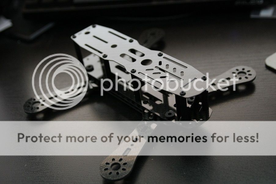
I chose this frame as I like the aesthetic and functional design overall, including the dirty plate/clean plate separation. Trinco, the designer of this frame over at FPV-Reconn also has longer arms sold separately to allow for 6" props. A nice possible future upgrade. The frame specs themselves are pretty standard:
-1mm thick top and bottom clean plates
-1.5mm thick top and bottom dirty plates
-3mm thick arms -M3 16x19 mount-
-2mm thick arms -M2 12x16 mount- (both sets are included)
-1mm thick camera plates -2 included, 35mm and 40mm tall-
-standard M3 hardware and mounting holes
The overall specs of this build:
RD230 Mini-H quad frame
Sunnysky X2204 2300KV motors
12A Blue Series ESCs - BLHeli flashed
Gemfan 5030 2 blade props
RTFQ Flip 1.5 - Multiwii 2.3
FrSky D4R-II in CPPM mode
Sony PZ0420 600TVL FPV camera
Hobbyking E-OSD - CL-OSD lite for voltage and RSSI display
ImmersionRC 5.8Ghz 600mw
ImmersionRC Spironet CP antenna
A couple notes pertaining to this build:
-The RD230 comes with 35mm and 40mm standoffs and camera plates. I'll be using the 35mm set. Trinco no longer includes both sets. The 40mm set is sold separately.
-I'm using 10mm M3 button head steel screws for added durability in a crash instead of nylon screws. Standoffs are still nylon.
-I got some dampeners from Infinity Hobby will be used instead of the included vibration balls.
-There will be two separate regulators, both from Polulu. A 5V step down for FC and RX power, and a 12V step up to power the camera from the VTX 5V out. This has the added bonus of allowing me to try 4S and worrying about it blasting off into the stratosphere rather than dealing with a fried ESC BEC, should I so desire.
-The FC pins are mounted in a low profile manner underneath ala Soma's method.
-I won't go into detail on flashing the ESCs or setting up Multiwii, with the exception of how I changed the orientation of the Flip 1.5 board to allow side access of the USB port at the end of the post.
This build took about a couple weeks to complete. The most time consuming part was the clean section, fitting everything into place and making up the custom length connectors and cables.
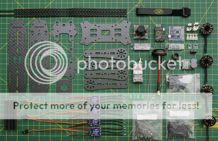
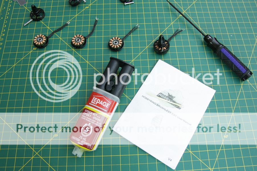
Here's a snippet of most of the parts for the build. Not included are a couple connectors and most of the wire that'll be used.
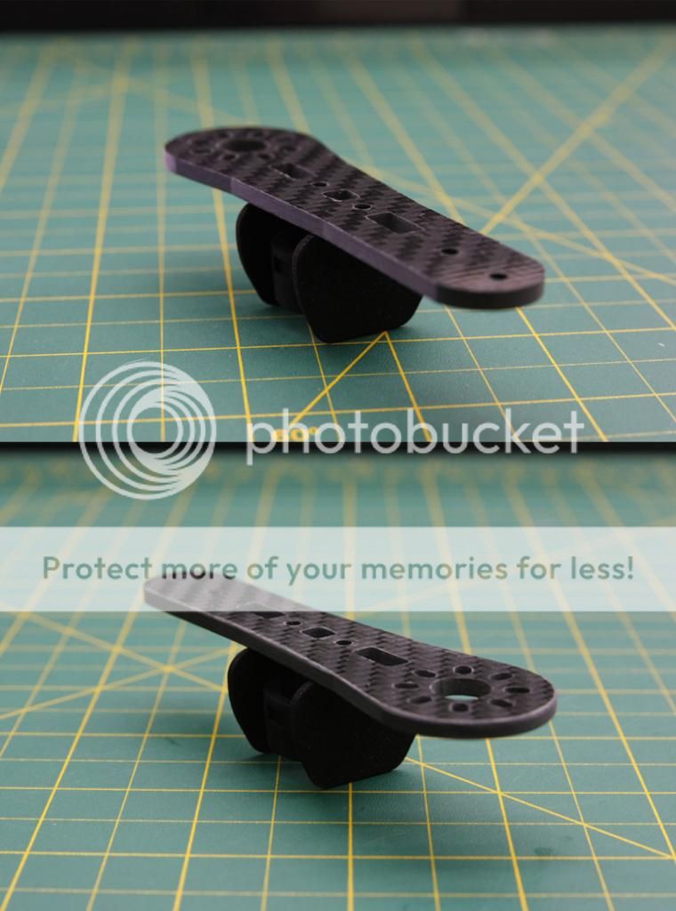
Carbon edge finishing
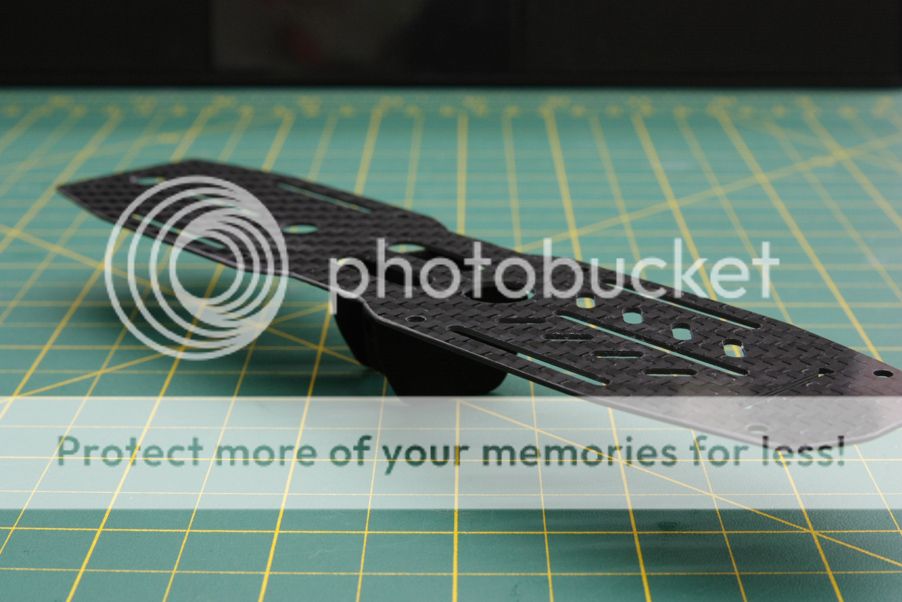
The edges of the arms and plates straight from cutting are pretty sharp. They need to be dulled down by using a file and sandpaper. This'll prevent cuts when handling the quad fully built and save the wires from wearing down and possibly shorting out. Not much to see but I'll reference Soma yet again as he has a great video going into carbon finishing. I don't have a nice workshop and a fine particle mask so I did it in my bathroom sink under some water.
A brief note here: this will take a while, don't do it while super tired or you'll rush. Rushing = bad. Had a small bit of chipping on one of the plates as I just didn't take my time, and the files I had were less than adequate. Needless to say it's still much better than not filed.
Arm before and after.
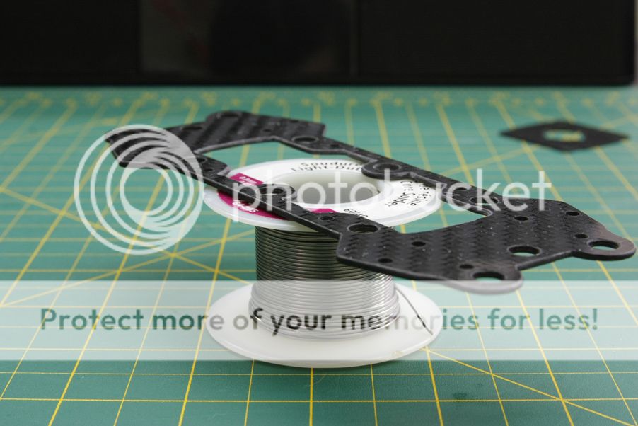
Top clean plate.
Top dirty plate. Took a bit more effort on this plate than the others specifically because plenty of wires will be sitting in this area and don't want any of them shorting out from the insulation being cut.
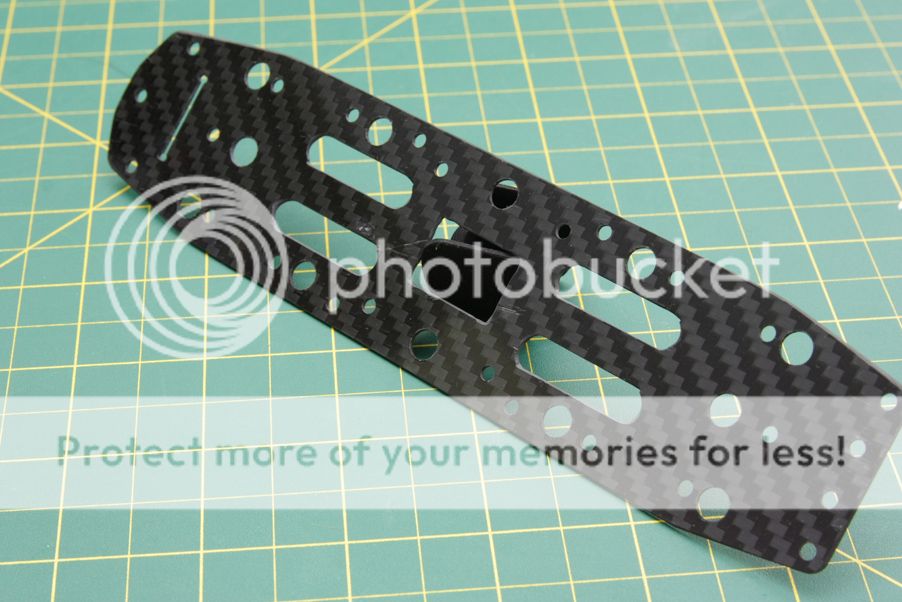
Bottom clean plate with a couple chips and scratches. You rush or are lazy, you'll get this.
Electronics prep
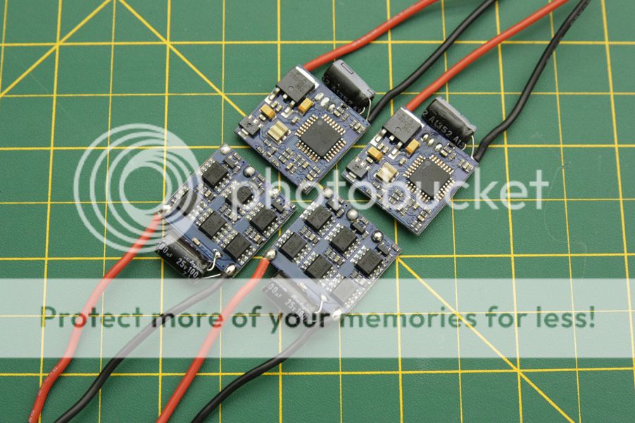
This build will be using standard Blueseries 12A ESCs, available under different titles from Hobbyking, Readytoflyquads, Timecop's online store and a variety of other places. They've been flashed with BLHeli Rev11.2, with the other popular option being SimonK's ESC firmware. I decided to go with BLHeli as changing the parameters on BLHeli is far easier than doing so on SimonK, and some still report desync issues even with the 05-15-03 SK firmware.
The flight controller that'll be used is a RTFQ Flip 1.5 running Multiwii 2.3. I've used this FC on a couple different builds and it's worked marvelously. The ability to tune PIDs using a smartphone app and bluetooth initially made this choice a very attractive one, and at $15 it's easily one of the cheapest flight controllers around. It requires a little more reading and setup than what a KK2 board would, but it's a small investment for how versatile Multiwii is as a multirotor platform.
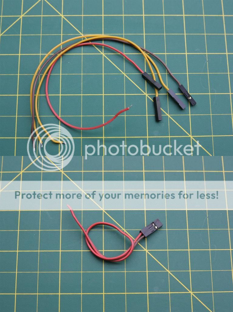
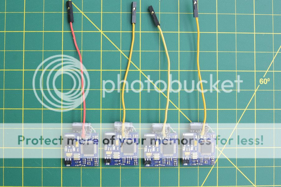
Delving into the actual prep, most of the wires have been removed from the ESCs for the time being. The motor wires were initially going to be soldered directly to them and only use one signal wire to connect each ESC to the FC. As this frame has a clean-dirty design with plenty of room to keep the ESCs safe between the clean and dirty plates, the ESCs will end up with most of the wires resoldered back on and at different lengths, tucked between the clean and dirty sections. The power wires are still left in place as a reminder of the polarity. Some of the servo wires will be reused individually with single crimp connector housings for the signal wires and a pair to supply power from the 5V regulator. The signal wires were removed to allow for proper resizing as necessary to get the neater wiring. The regulators themselves haven't been soldered up yet, they'll be done when work on the power harness is underway.
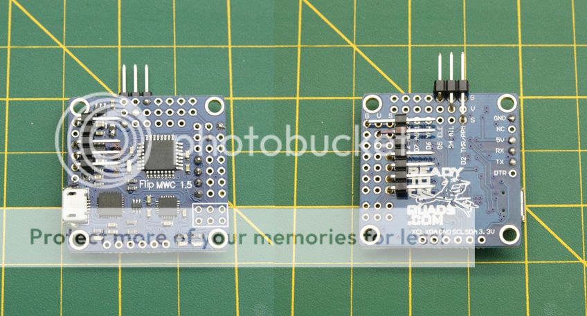
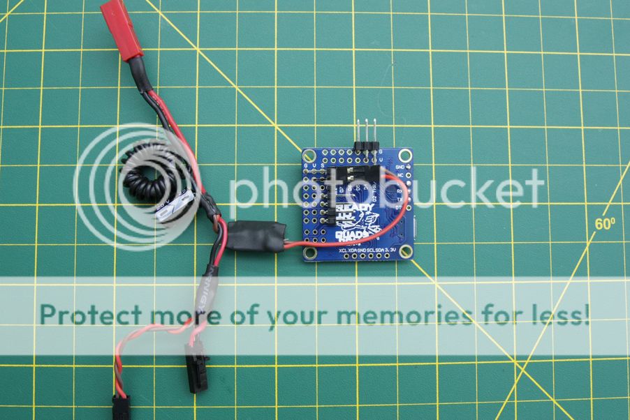
Soldered the pins on low profile style similar to how Soma does on his flip boards. The power and signal wire pins are underneath in a single layer, the receiver connector is on the front of the board and the pins to hook up a bluetooth module are on the opposite side of the signal pins on top. The pictures do a better job explaining:
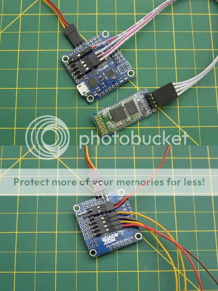
As I'll be using my D4R-II in CPPM mode, this makes for a reasonably clean single wire setup.
You can see the power connector is slightly crooked from pushing up against the signal pin for the receiver connection. It shouldn't be a problem however I'll likely file a small divot in the housing to make it sit more flush and potentially stop the connector from coming out randomly.
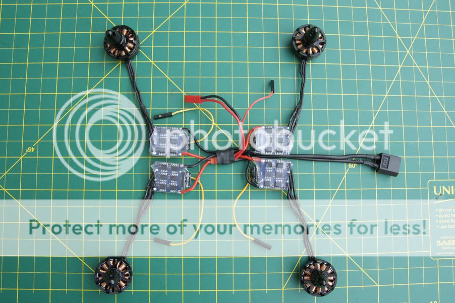
Motor prep and part layout
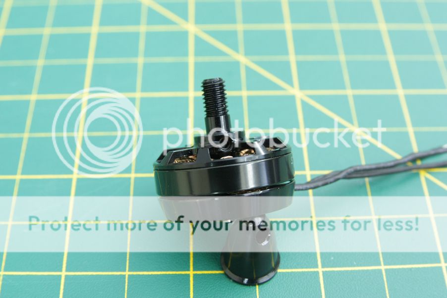
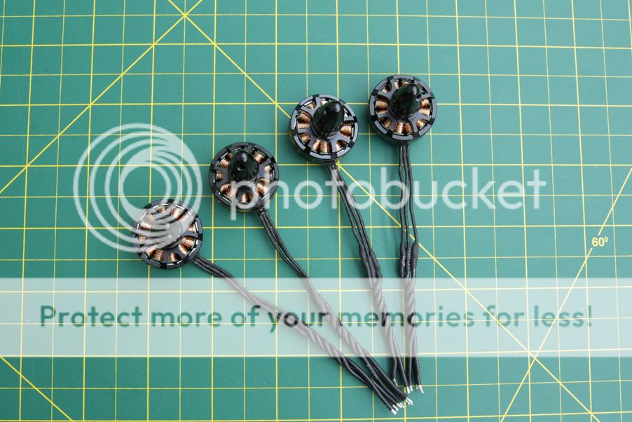
Alrighty. Time for motor prep. This build is using those oh-so-popular Sunnysky X2204 2300kv motors. A nice balance between cost, quality and power. Having only used the RCX 1804 motors before, these ones are marvelous.
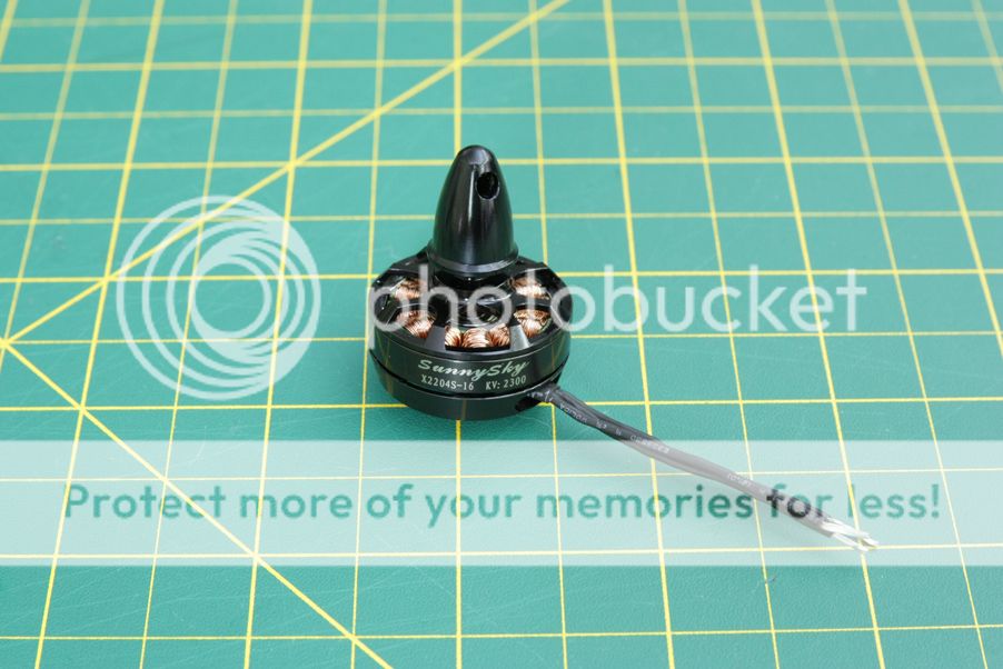
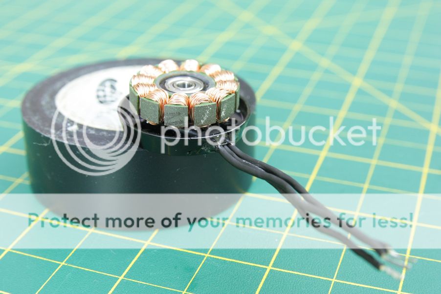
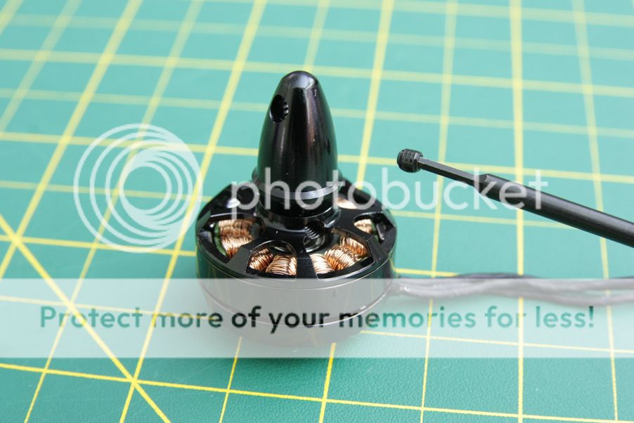
In order to take off the motor bell you have to remove the two grub screws on either side. This requires a 1.5mm hex driver.
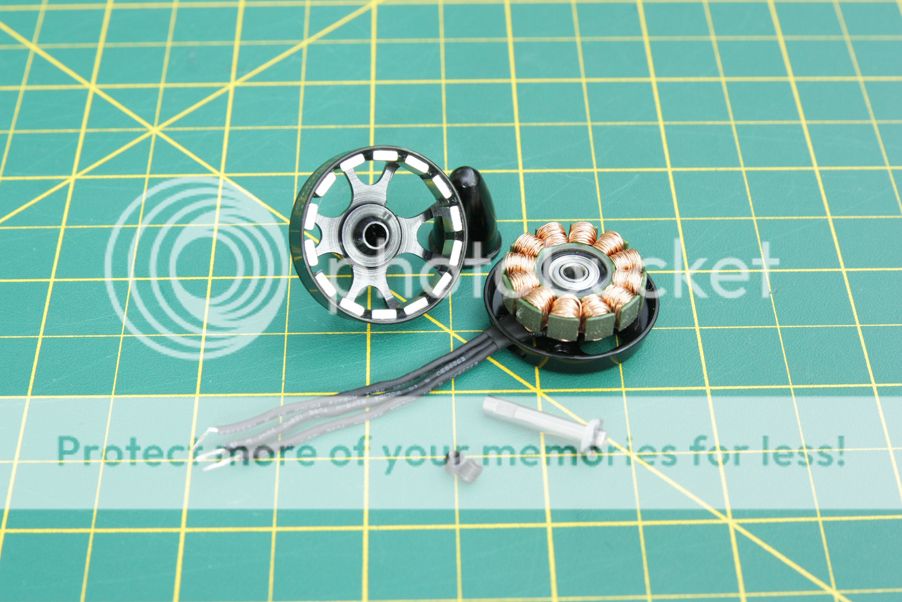
The disassembled motor. The motor bells were removed while epoxying the motor wires just as an added measure against a mistake. One of the motor bells were stubborn and wouldn't come off at first so it got the same treatment with the bell on. No harm done, no epoxy going where it shouldn't have.
No pictures of the actual process of applying the epoxy were taken as there wasn't much time to allow for it, so I'll yet again reference one of Soma's lovely videos that go into detail on the process. It's a relatively straightforward affair. Some 5 minute epoxy from Canadian tire was used and applied with a toothpick. Easy peasy.
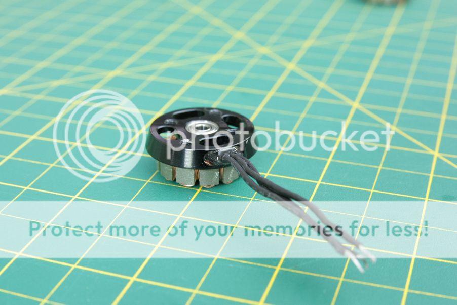
And what it looks like when all is said and done. These motor wires won't be yanked out any time soon.
Finally on reassembly, loctite was used on the grubscrews. Nobody would want a motor bell to pop off mid flight, so this part is definitely an important step when prepping any brushless motors. The landing from such an even would be spectacular, however.
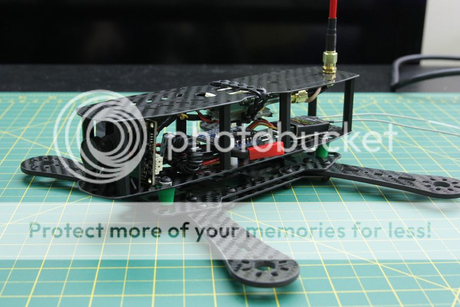
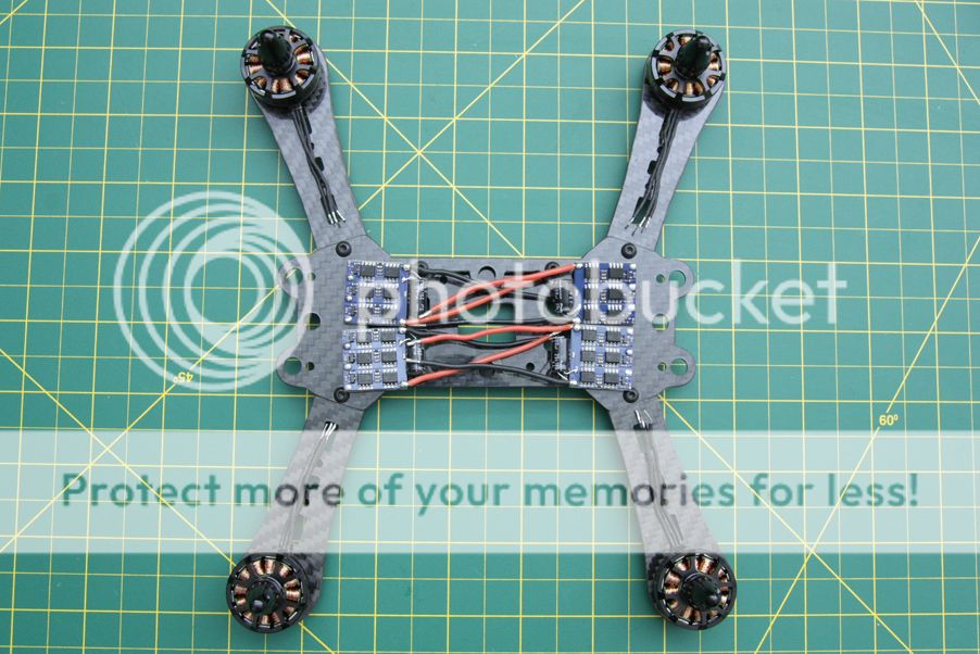
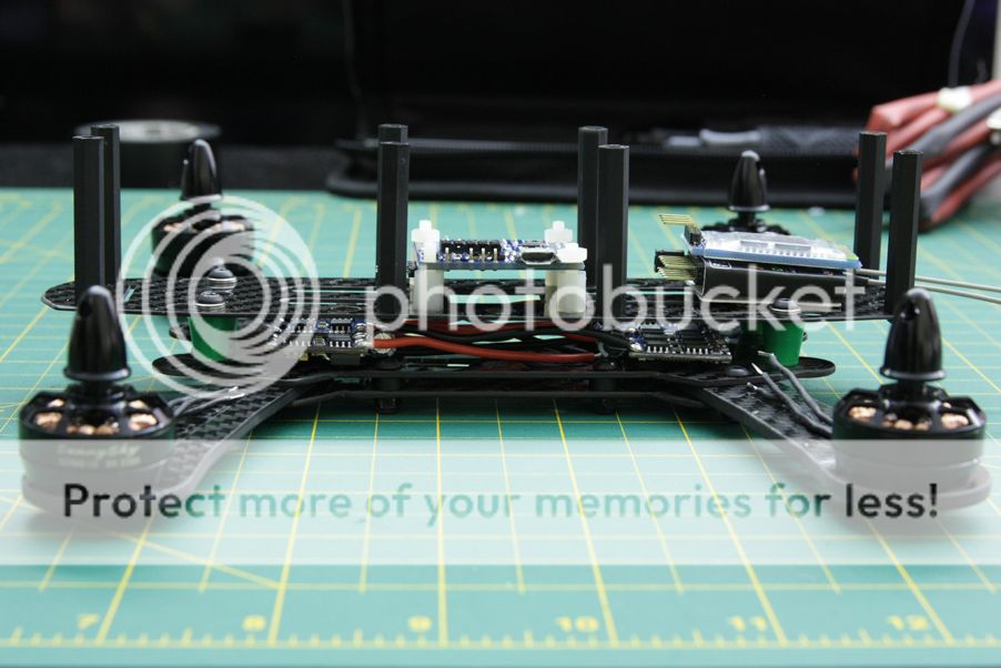
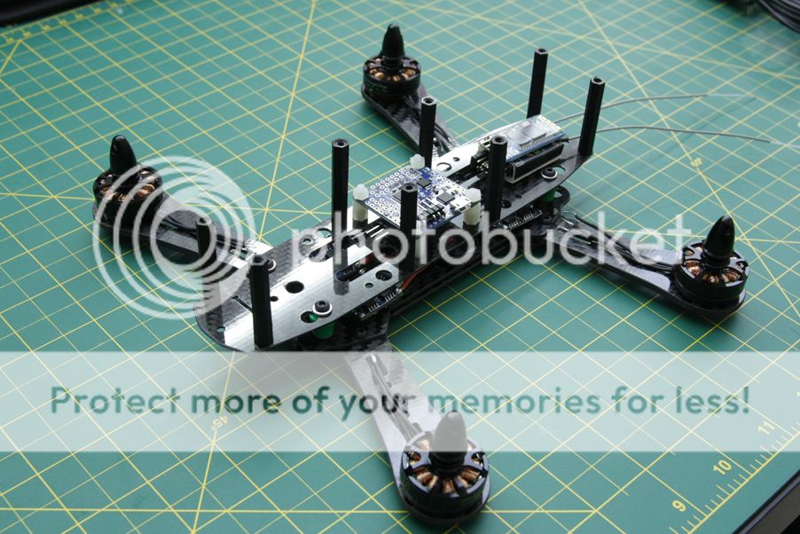
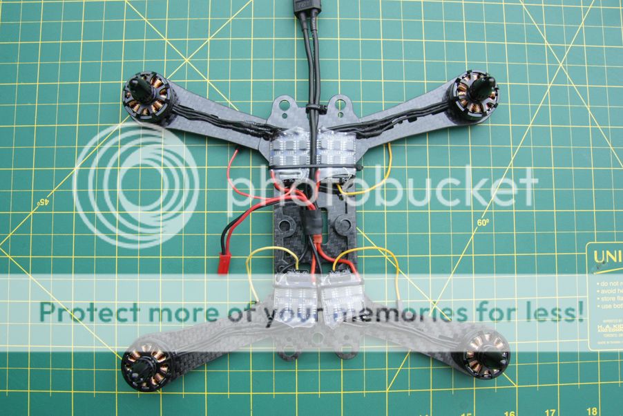
Main component layout
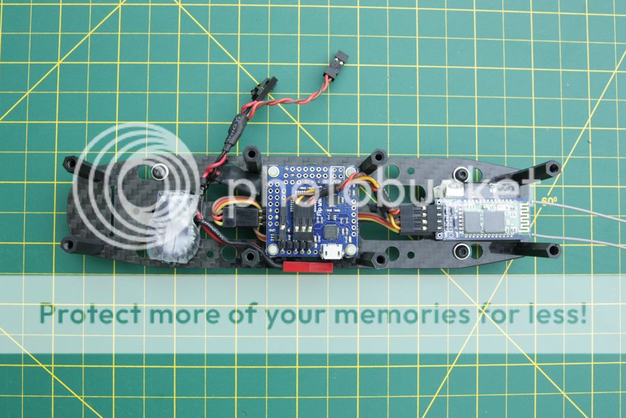
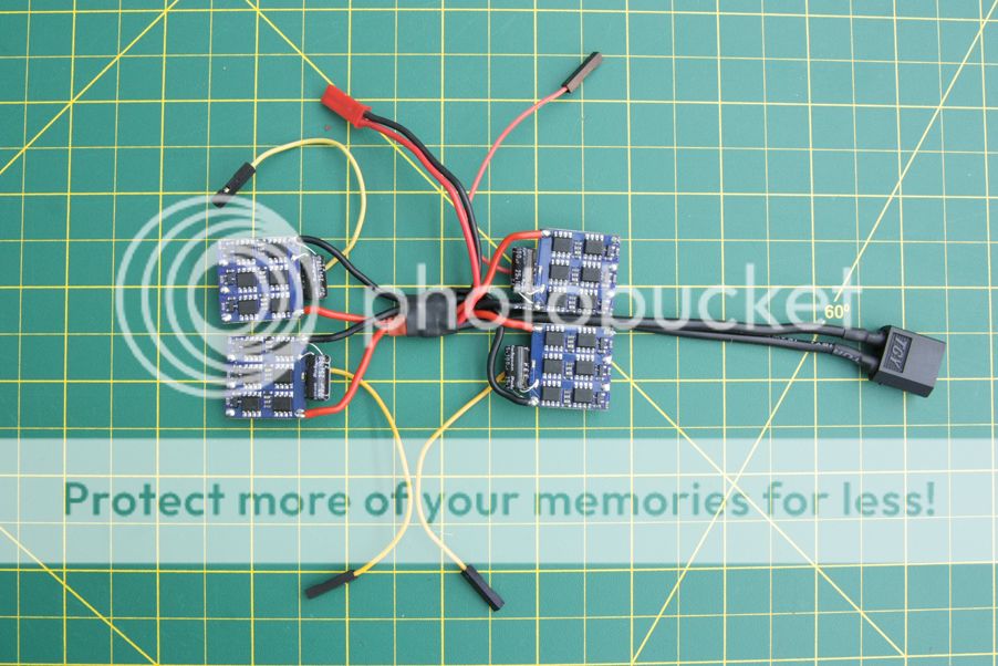
Just a rough layout of the main parts. The couple wires up front were for the OSD and 12V step up, which have been slightly relocated for a tidier fit.I decided to forgo this setup as I was having video issues with it and the OSD both hooked up to the camera for a reason I couldn't figure out other than a faulty OSD. see below
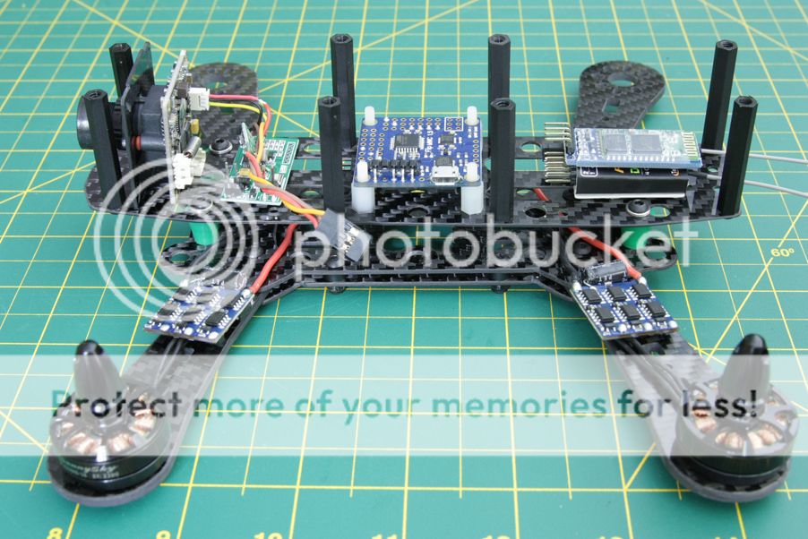
The ESCs will end up on the dirty plate instead of on the arms. This'll have a cleaner appearance and protect the ESCs from a lot of potential damage from striking trees and the like.
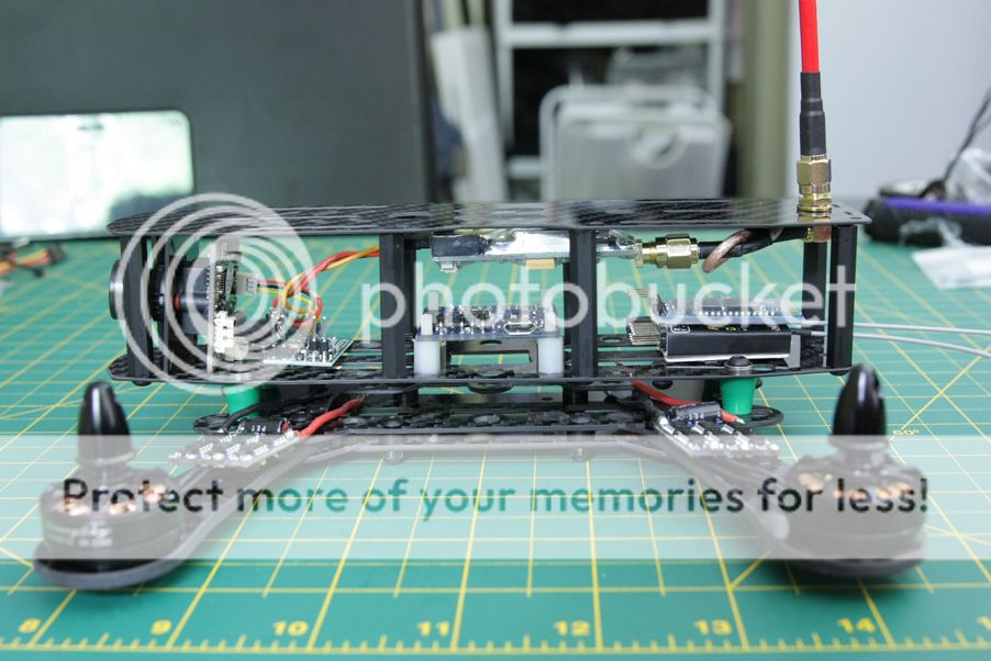
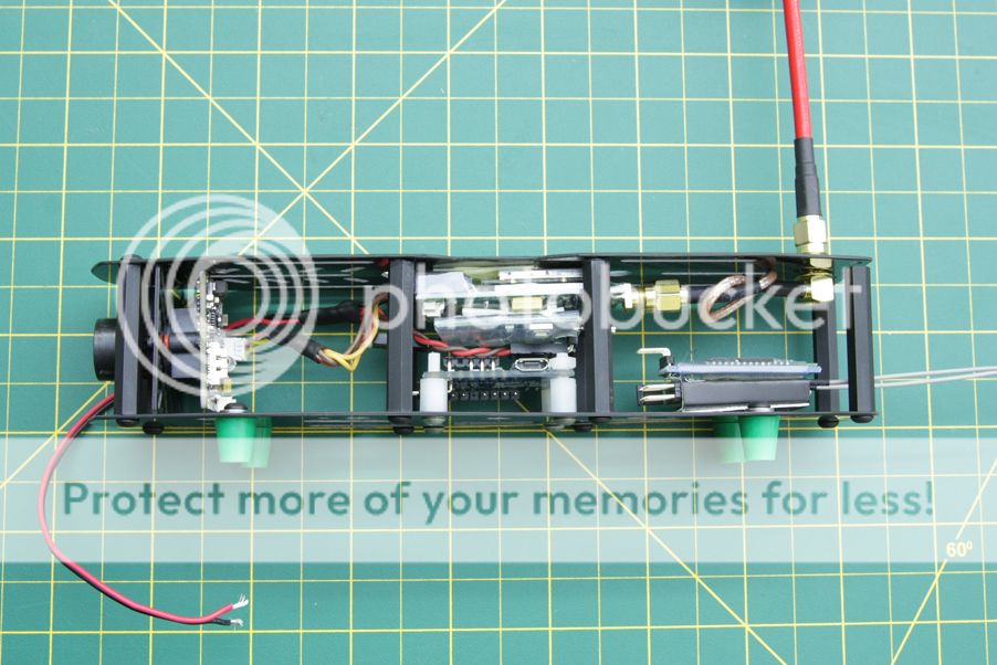
Video system and clean section wiring
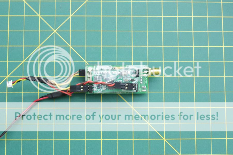
The FPV setup on this quad will be fairly standard, using an ImmersionRC 600mw 5.8ghz video transmitter, an ImmersionRC spironet CP antenna and a Sony PZ0420 FPV camera with a 2.8mm lens. Between the transmitter and antenna is a 4" SMA to right angle SMA extension. This allows the VTX antenna to sit nice and high from the body of the quad while also allowing it to be a failure point in larger crashes, instead of tearing off the SMA connector on the VTX. Better to replace a 5$ part than a $70 one.
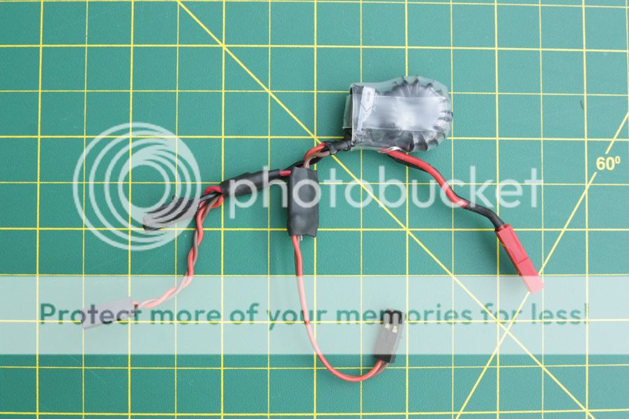
I decided I'll be running the camera off of the main pack voltage instead of through the 12V step up. Perhaps coincidence with an OSD that was giving me grief, the 12V step up and now trashed E-OSD were not playing nicely. I had another E-OSD fortunately, and after testing it with the camera directly powered through the main pack voltage it works without complaint. I also tested to make sure the camera would operate down to 10V and it does, so for heavy throttle usage near the end of the pack shouldn't end up in the camera rebooting from voltage sag.
I felt like giving the 12V step up another try to see if it'd play nicely with the second OSD. Wired it up separately from the main power and sure enough, no OSD distortions, no video cutting out, everything is golden and works as it's supposed to. A minor sidetrack, but this now allows me to stick to my original plan to keep all the electronics separated from the main power supply to allow for flexibility in using both 3S and 4S should it be desired, and allow the camera to operate under any conditions as it will always have a steady 12V supply.
The OSD itself will be directly underneath the VTX. This greatly reduces wiring going all over and convenient for connecting RSSI as the receiver will sit in the back. The wiring harness is also done up all nice and neat with just enough slack to allow for movement during undesirable "landings".
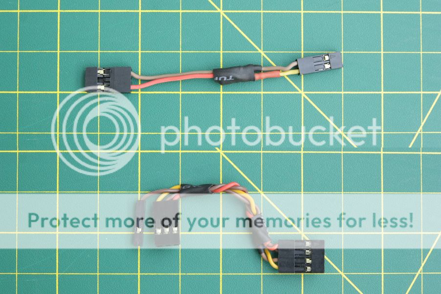
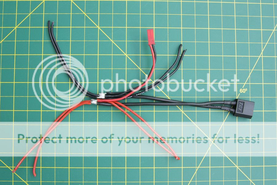
The previous harness with the camera directly powered off of the flight pack.
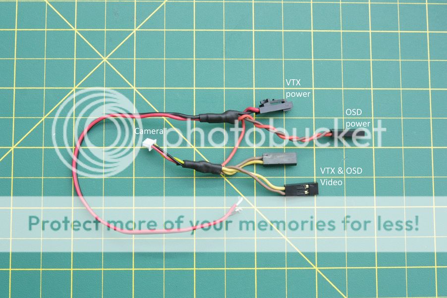
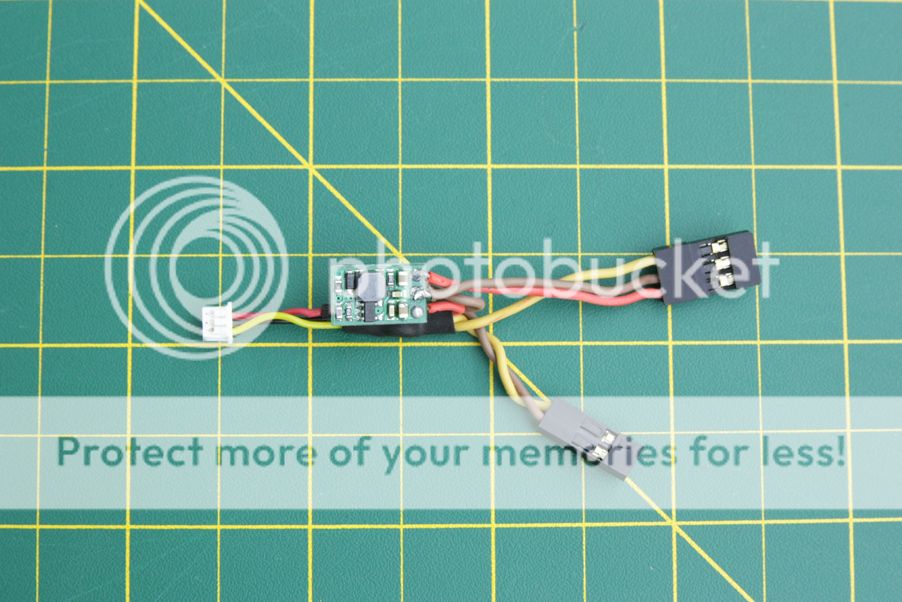
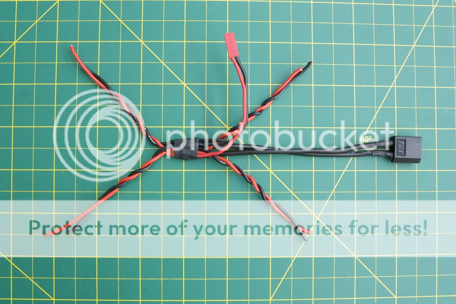
New harness. Essentially the same as above, with the video and power lines completely separate.
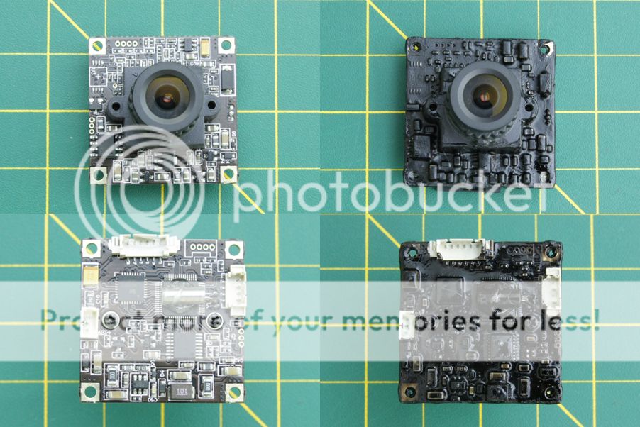
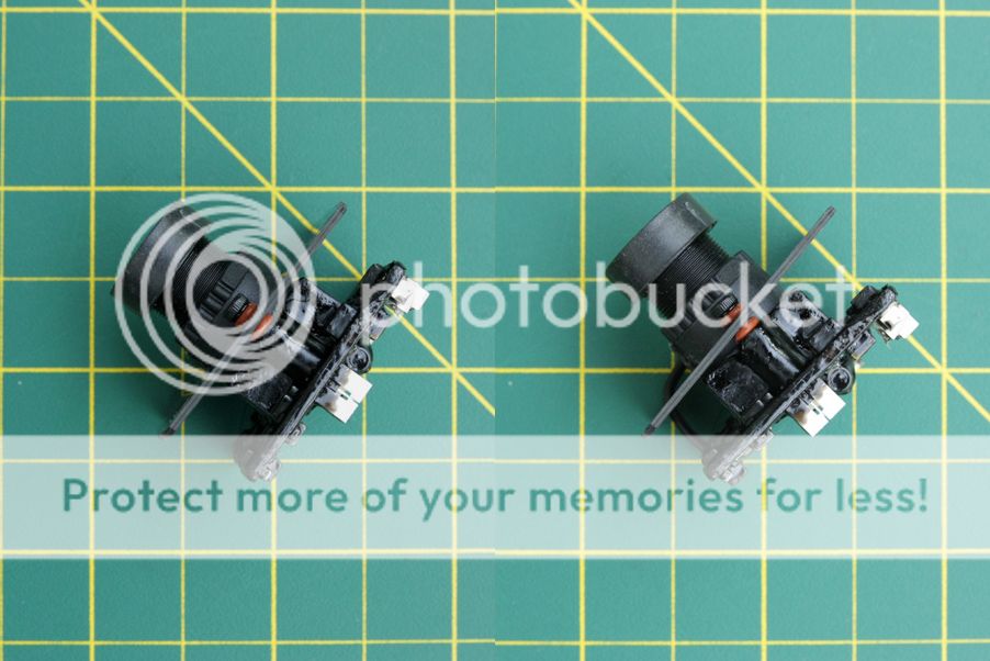
Not a heck of a lot to do in regards to the camera other than set it up using the included OSD controls, add a drop of hotglue to secure the silver crystal oscillator and coat it with some liquid electrical tape to make it mostly watertight.
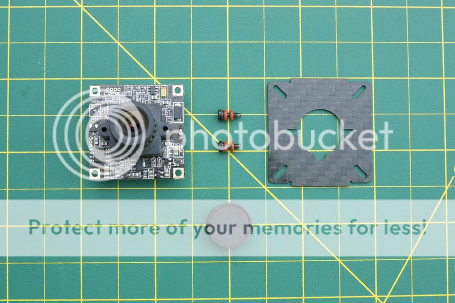
Before and after using the liquid electrical tape.
The camera will be mounted to the camera plate using the two M2 screws shown above and some zipties. Doing so in this manner allows the camera to be angled up a few degrees to see a little more of what's ahead instead of the ground during some fast forward flight, while also not allowing any movement for the camera to twist.
Onto another little note, I've never flown with an OSD but wanted to give it a try. Doing so works two fold in my favor, allowing me to monitor the pack voltage when the alarm might be out of earshot, while also giving a little more flexibility in flight times depending on flying style instead of relying on a set timer. For this I decided to use HK's cheap E-OSD. Following this guide, the E-OSD was flashed to a stripped down version of CL-OSD, an open source firmware alternative for the E-OSD and G-OSD that Hobbyking sells. It allows for easy voltage calibration, RSSI display through the second battery connection, and the ability to reset the timer on a press of the button, which isn't something the E-OSD can do stock.
The E-OSD on the stock firmware would display something like this:

The E-OSD flashed with CL-OSD now displays this:

A minor difference. The ability to reset the timer as needed and get an easy RSSI readout are the two driving reasons I decided to change the firmware.
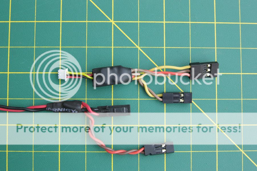
Moving on to the rest of the wiring. For the sake of simplicity if I need to get into the dirty section to replace an ESC or double check some soldering connections to the motors, this build will have two separate power harnesses joined by a JST connection to allow removal of the top section without the need to desolder anything. One on the clean plates, providing all the necessary power to the video and control system while the other will be on the dirty plate with the ESCs and main power connector.
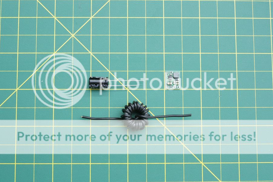
To 'clean' the power I'm using a simple LC filter, consisting of a ferrite ring wrapped in insulated wire and a 470uf capacitor. While this might not be necessary for the VTX - video connection which is already filtered, there's still the possibility of noise entering the video system from the OSD being directly connected to the flight pack. Adding the LC filter before everything is an extra countermeasure to prevent noise coming in through any power connection and saving future headaches.
The last components for the power supply before they're soldered up. The wrapped ferrite ring, capacitor, and a 5V step down regulator.
Soldered together and heatshrunk. The VTX/OSD power cables that were posted above and 5V step down are connected to the LC filter with a JST plug on the end. Used some liquid electrical tape underneath the capacitor to completely seal the terminals.
The extra slack on the FC cable is tucked neatly under the FC, but still allows it to be removed from the standoffs without kinking the wire.
A couple more cables done up. The top one is just a low pass filter consisting of a 1uf capacitor and 10k ohm resistor soldered together and heatshrunk. This is necessary for the OSD to measure the RSSI level coming from the receiver, more information here.
The bottom cable is just a custom length cable for the bluetooth module.
Top view
All wired up and nice and pretty. Top section is 98% done, everything just needs to be secured down with tape and zipties which is fairly self explanatory. The small C-ring and washer on the right angle SMA connector were replaced with a couple of M6 brass washers on top and below to dissipate the force from any impacts on the antenna. Plus it looks nice.
Dirty power harness
This section will entail the assembly of the entire power train; power harness, ESCs and motors.
The motors themselves didn't need much other than extending the wires to reach the ESCs between the clean and dirty plates. The previous ESC wires weren't populated on anything else, so they were used.
Removed the remaining power wires off of the ESCs and soldered the signal connections back on after figuring out an appropriate length. Used some hot glue as an added security measure on the signal wires.
The primary power harness soldered all together. The solder joints were purposely offset again to reduce the chances of contact if the shrinkwrap wears out. The JST plug is for the clean section harness.
Covered the joints with liquid electrical tape and then heatshrink. The extra length was intended so the wires could be trimmed to the appropriate length, although I ended up drastically overestimating the length of the power wires.
Finally, the ESCs soldered to the power harness.
The motor wires soldered to the ESCs. Because of the layout of the ESCs underneath, the wires were cut to the appropriate lengths and soldered on at an angle. The ESCs were then heatshrunk. There were a couple areas where the heatshrink didn't cover from how one motor wire was attached and came off the board, so a bit of liquid electrical tape was used on those edges for added measure against shorting something out.
And mounted to the dirty plates. The ESCs were secured with double sided foam tape and zipties.
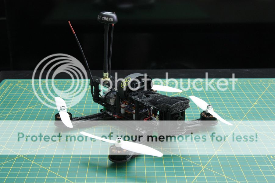
Finished product
With that final note, all that was left was to assemble all the main parts together. There wasn't much to see or explain through the final assembly as it was relatively straight forward. Dirty section to clean section, put the motor wires and power cable through, and plug everything in one last time. With each view of the machine I'll just iterate on what else was done that didn't require pictures.
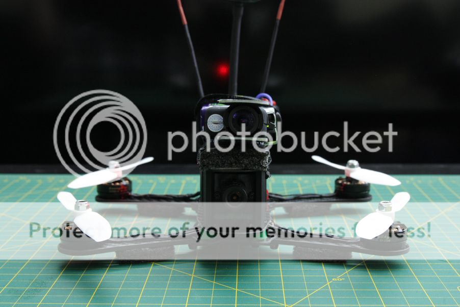
Front view. Some black packing foam I had laying around was ziptied to the arms to act as a low profile landing gear.
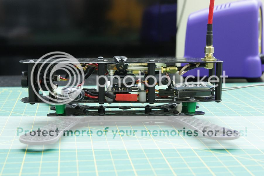
Right side view. I put a dab of hot glue over the camera plug to keep it in place. Probably not required, but better to be safe than sorry. The OSD button is also accessed from this side to reset the timer, although not very visible from the blinding LED. The M6 brass washers are also visible on the SMA extension. A little bit of loctite was put on the nut to keep it in place.
Rear view. Covered the VTX antenna in some black heatshrink. The D4R-II antennas were heatshrunk with some zipties for added support. The red shrinkwrap serves no purpose other than aesthetics. I used a black XT-60 plug with black wire as well to keep with the 'blacked out' look for the power cable. It's secured to the right rear standoff and has enough slack to easily plug in and remove the battery, but not enough to interfere with the props or anything else.
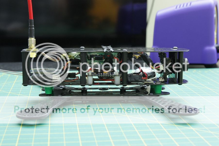
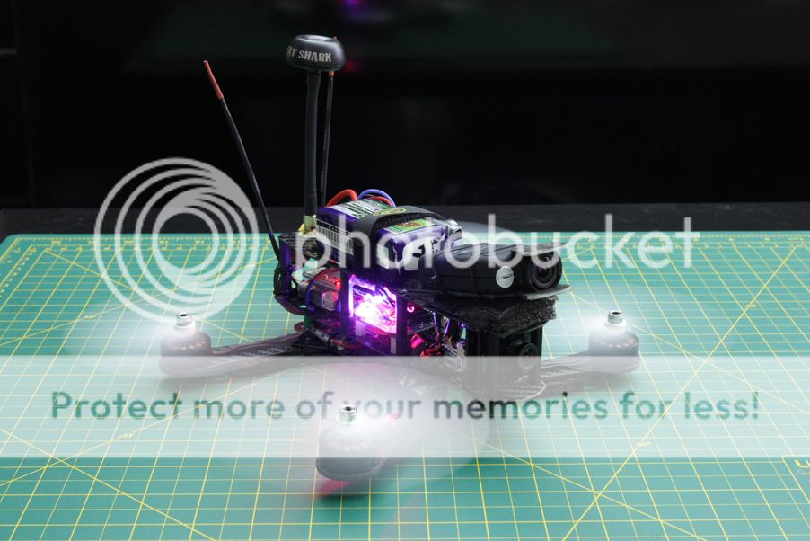
Left side view. The Flip 1.5's stock orientation is with the USB port facing forward. This made it very, very inconvenient to change some parameters in that can only be done in the sketch or connect to the computer to use the Multiwii GUI. A couple lines were added to the sketch to reorient the board so that the USB port was on the left, I'll put the tidbit with some instructions near the end of the post, for anyone interested. The JST plugs that connect the clean and dirty power harnesses are also visible on this side for ease of access when needed, but won't come unplugged without a fair bit of effort.
The foam mount for the Mobius camera was made using the same foam on the arms, cut at an angle. It's secured to the frame by zipties and double sided foam tape, with some velcro on top to mount the Mobius. The camera was mounted at an angle so that during fast forward flight, the camera's view would be straight ahead instead of facing the ground most of the time. It definitely makes a difference.
And some GIFs to show the build off")
Flip 1.5 orientation change
Like I had posted above, the Flip 1.5's stock orientation was less than adequate for my needs so I changed it. This explanation is for those comfortable with Multiwii and the Arduino IDE.
The change was done by adding two little chunks of code into the sketch.
In config.h, under boards and sensor definitions comment out #define FLYDUINO_MPU. Add the following line in this section:
In def.h add the following under IMU Orientations and Sensor definitions
Verify that the sketch will compile before attempting to flash.
I went searching for this and came across it on RCGroups, so I figured I'd share it. I haven't bothered working out the other orientations but comparing this and the stock Flyduino sensor definitions it should be relatively easy.
I chose this frame as I like the aesthetic and functional design overall, including the dirty plate/clean plate separation. Trinco, the designer of this frame over at FPV-Reconn also has longer arms sold separately to allow for 6" props. A nice possible future upgrade. The frame specs themselves are pretty standard:
-1mm thick top and bottom clean plates
-1.5mm thick top and bottom dirty plates
-3mm thick arms -M3 16x19 mount-
-2mm thick arms -M2 12x16 mount- (both sets are included)
-1mm thick camera plates -2 included, 35mm and 40mm tall-
-standard M3 hardware and mounting holes
The overall specs of this build:
RD230 Mini-H quad frame
Sunnysky X2204 2300KV motors
12A Blue Series ESCs - BLHeli flashed
Gemfan 5030 2 blade props
RTFQ Flip 1.5 - Multiwii 2.3
FrSky D4R-II in CPPM mode
Sony PZ0420 600TVL FPV camera
Hobbyking E-OSD - CL-OSD lite for voltage and RSSI display
ImmersionRC 5.8Ghz 600mw
ImmersionRC Spironet CP antenna
A couple notes pertaining to this build:
-
-I'm using 10mm M3 button head steel screws for added durability in a crash instead of nylon screws. Standoffs are still nylon.
-I got some dampeners from Infinity Hobby will be used instead of the included vibration balls.
-There will be two separate regulators, both from Polulu. A 5V step down for FC and RX power, and a 12V step up to power the camera from the VTX 5V out. This has the added bonus of allowing me to try 4S and worrying about it blasting off into the stratosphere rather than dealing with a fried ESC BEC, should I so desire.
-The FC pins are mounted in a low profile manner underneath ala Soma's method.
-I won't go into detail on flashing the ESCs or setting up Multiwii, with the exception of how I changed the orientation of the Flip 1.5 board to allow side access of the USB port at the end of the post.
This build took about a couple weeks to complete. The most time consuming part was the clean section, fitting everything into place and making up the custom length connectors and cables.
Here's a snippet of most of the parts for the build. Not included are a couple connectors and most of the wire that'll be used.
Carbon edge finishing
The edges of the arms and plates straight from cutting are pretty sharp. They need to be dulled down by using a file and sandpaper. This'll prevent cuts when handling the quad fully built and save the wires from wearing down and possibly shorting out. Not much to see but I'll reference Soma yet again as he has a great video going into carbon finishing. I don't have a nice workshop and a fine particle mask so I did it in my bathroom sink under some water.
A brief note here: this will take a while, don't do it while super tired or you'll rush. Rushing = bad. Had a small bit of chipping on one of the plates as I just didn't take my time, and the files I had were less than adequate. Needless to say it's still much better than not filed.
Arm before and after.
Top clean plate.
Top dirty plate. Took a bit more effort on this plate than the others specifically because plenty of wires will be sitting in this area and don't want any of them shorting out from the insulation being cut.
Bottom clean plate with a couple chips and scratches. You rush or are lazy, you'll get this.
Electronics prep
This build will be using standard Blueseries 12A ESCs, available under different titles from Hobbyking, Readytoflyquads, Timecop's online store and a variety of other places. They've been flashed with BLHeli Rev11.2, with the other popular option being SimonK's ESC firmware. I decided to go with BLHeli as changing the parameters on BLHeli is far easier than doing so on SimonK, and some still report desync issues even with the 05-15-03 SK firmware.
The flight controller that'll be used is a RTFQ Flip 1.5 running Multiwii 2.3. I've used this FC on a couple different builds and it's worked marvelously. The ability to tune PIDs using a smartphone app and bluetooth initially made this choice a very attractive one, and at $15 it's easily one of the cheapest flight controllers around. It requires a little more reading and setup than what a KK2 board would, but it's a small investment for how versatile Multiwii is as a multirotor platform.
Delving into the actual prep, most of the wires have been removed from the ESCs for the time being. The motor wires were initially going to be soldered directly to them and only use one signal wire to connect each ESC to the FC. As this frame has a clean-dirty design with plenty of room to keep the ESCs safe between the clean and dirty plates, the ESCs will end up with most of the wires resoldered back on and at different lengths, tucked between the clean and dirty sections. The power wires are still left in place as a reminder of the polarity. Some of the servo wires will be reused individually with single crimp connector housings for the signal wires and a pair to supply power from the 5V regulator. The signal wires were removed to allow for proper resizing as necessary to get the neater wiring. The regulators themselves haven't been soldered up yet, they'll be done when work on the power harness is underway.
Soldered the pins on low profile style similar to how Soma does on his flip boards. The power and signal wire pins are underneath in a single layer, the receiver connector is on the front of the board and the pins to hook up a bluetooth module are on the opposite side of the signal pins on top. The pictures do a better job explaining:
As I'll be using my D4R-II in CPPM mode, this makes for a reasonably clean single wire setup.
You can see the power connector is slightly crooked from pushing up against the signal pin for the receiver connection. It shouldn't be a problem however I'll likely file a small divot in the housing to make it sit more flush and potentially stop the connector from coming out randomly.
Motor prep and part layout
Alrighty. Time for motor prep. This build is using those oh-so-popular Sunnysky X2204 2300kv motors. A nice balance between cost, quality and power. Having only used the RCX 1804 motors before, these ones are marvelous.
In order to take off the motor bell you have to remove the two grub screws on either side. This requires a 1.5mm hex driver.
The disassembled motor. The motor bells were removed while epoxying the motor wires just as an added measure against a mistake. One of the motor bells were stubborn and wouldn't come off at first so it got the same treatment with the bell on. No harm done, no epoxy going where it shouldn't have.
No pictures of the actual process of applying the epoxy were taken as there wasn't much time to allow for it, so I'll yet again reference one of Soma's lovely videos that go into detail on the process. It's a relatively straightforward affair. Some 5 minute epoxy from Canadian tire was used and applied with a toothpick. Easy peasy.
And what it looks like when all is said and done. These motor wires won't be yanked out any time soon.
Finally on reassembly, loctite was used on the grubscrews. Nobody would want a motor bell to pop off mid flight, so this part is definitely an important step when prepping any brushless motors. The landing from such an even would be spectacular, however.
Main component layout
Just a rough layout of the main parts. The couple wires up front were for the OSD and 12V step up, which have been slightly relocated for a tidier fit.
The ESCs will end up on the dirty plate instead of on the arms. This'll have a cleaner appearance and protect the ESCs from a lot of potential damage from striking trees and the like.
Video system and clean section wiring
The FPV setup on this quad will be fairly standard, using an ImmersionRC 600mw 5.8ghz video transmitter, an ImmersionRC spironet CP antenna and a Sony PZ0420 FPV camera with a 2.8mm lens. Between the transmitter and antenna is a 4" SMA to right angle SMA extension. This allows the VTX antenna to sit nice and high from the body of the quad while also allowing it to be a failure point in larger crashes, instead of tearing off the SMA connector on the VTX. Better to replace a 5$ part than a $70 one.
I felt like giving the 12V step up another try to see if it'd play nicely with the second OSD. Wired it up separately from the main power and sure enough, no OSD distortions, no video cutting out, everything is golden and works as it's supposed to. A minor sidetrack, but this now allows me to stick to my original plan to keep all the electronics separated from the main power supply to allow for flexibility in using both 3S and 4S should it be desired, and allow the camera to operate under any conditions as it will always have a steady 12V supply.
The OSD itself will be directly underneath the VTX. This greatly reduces wiring going all over and convenient for connecting RSSI as the receiver will sit in the back. The wiring harness is also done up all nice and neat with just enough slack to allow for movement during undesirable "landings".
The previous harness with the camera directly powered off of the flight pack.
New harness. Essentially the same as above, with the video and power lines completely separate.
Not a heck of a lot to do in regards to the camera other than set it up using the included OSD controls, add a drop of hotglue to secure the silver crystal oscillator and coat it with some liquid electrical tape to make it mostly watertight.
Before and after using the liquid electrical tape.
The camera will be mounted to the camera plate using the two M2 screws shown above and some zipties. Doing so in this manner allows the camera to be angled up a few degrees to see a little more of what's ahead instead of the ground during some fast forward flight, while also not allowing any movement for the camera to twist.
Onto another little note, I've never flown with an OSD but wanted to give it a try. Doing so works two fold in my favor, allowing me to monitor the pack voltage when the alarm might be out of earshot, while also giving a little more flexibility in flight times depending on flying style instead of relying on a set timer. For this I decided to use HK's cheap E-OSD. Following this guide, the E-OSD was flashed to a stripped down version of CL-OSD, an open source firmware alternative for the E-OSD and G-OSD that Hobbyking sells. It allows for easy voltage calibration, RSSI display through the second battery connection, and the ability to reset the timer on a press of the button, which isn't something the E-OSD can do stock.
The E-OSD on the stock firmware would display something like this:
The E-OSD flashed with CL-OSD now displays this:
A minor difference. The ability to reset the timer as needed and get an easy RSSI readout are the two driving reasons I decided to change the firmware.
Moving on to the rest of the wiring. For the sake of simplicity if I need to get into the dirty section to replace an ESC or double check some soldering connections to the motors, this build will have two separate power harnesses joined by a JST connection to allow removal of the top section without the need to desolder anything. One on the clean plates, providing all the necessary power to the video and control system while the other will be on the dirty plate with the ESCs and main power connector.
To 'clean' the power I'm using a simple LC filter, consisting of a ferrite ring wrapped in insulated wire and a 470uf capacitor. While this might not be necessary for the VTX - video connection which is already filtered, there's still the possibility of noise entering the video system from the OSD being directly connected to the flight pack. Adding the LC filter before everything is an extra countermeasure to prevent noise coming in through any power connection and saving future headaches.
The last components for the power supply before they're soldered up. The wrapped ferrite ring, capacitor, and a 5V step down regulator.
Soldered together and heatshrunk. The VTX/OSD power cables that were posted above and 5V step down are connected to the LC filter with a JST plug on the end. Used some liquid electrical tape underneath the capacitor to completely seal the terminals.
The extra slack on the FC cable is tucked neatly under the FC, but still allows it to be removed from the standoffs without kinking the wire.
A couple more cables done up. The top one is just a low pass filter consisting of a 1uf capacitor and 10k ohm resistor soldered together and heatshrunk. This is necessary for the OSD to measure the RSSI level coming from the receiver, more information here.
The bottom cable is just a custom length cable for the bluetooth module.
Top view
All wired up and nice and pretty. Top section is 98% done, everything just needs to be secured down with tape and zipties which is fairly self explanatory. The small C-ring and washer on the right angle SMA connector were replaced with a couple of M6 brass washers on top and below to dissipate the force from any impacts on the antenna. Plus it looks nice.
Dirty power harness
This section will entail the assembly of the entire power train; power harness, ESCs and motors.
The motors themselves didn't need much other than extending the wires to reach the ESCs between the clean and dirty plates. The previous ESC wires weren't populated on anything else, so they were used.
Removed the remaining power wires off of the ESCs and soldered the signal connections back on after figuring out an appropriate length. Used some hot glue as an added security measure on the signal wires.
The primary power harness soldered all together. The solder joints were purposely offset again to reduce the chances of contact if the shrinkwrap wears out. The JST plug is for the clean section harness.
Covered the joints with liquid electrical tape and then heatshrink. The extra length was intended so the wires could be trimmed to the appropriate length, although I ended up drastically overestimating the length of the power wires.
Finally, the ESCs soldered to the power harness.
The motor wires soldered to the ESCs. Because of the layout of the ESCs underneath, the wires were cut to the appropriate lengths and soldered on at an angle. The ESCs were then heatshrunk. There were a couple areas where the heatshrink didn't cover from how one motor wire was attached and came off the board, so a bit of liquid electrical tape was used on those edges for added measure against shorting something out.
And mounted to the dirty plates. The ESCs were secured with double sided foam tape and zipties.
Finished product
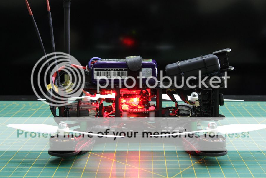
With that final note, all that was left was to assemble all the main parts together. There wasn't much to see or explain through the final assembly as it was relatively straight forward. Dirty section to clean section, put the motor wires and power cable through, and plug everything in one last time. With each view of the machine I'll just iterate on what else was done that didn't require pictures.
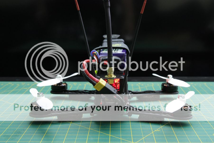
Front view. Some black packing foam I had laying around was ziptied to the arms to act as a low profile landing gear.
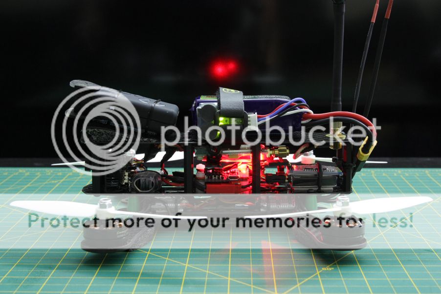
Right side view. I put a dab of hot glue over the camera plug to keep it in place. Probably not required, but better to be safe than sorry. The OSD button is also accessed from this side to reset the timer, although not very visible from the blinding LED. The M6 brass washers are also visible on the SMA extension. A little bit of loctite was put on the nut to keep it in place.
Rear view. Covered the VTX antenna in some black heatshrink. The D4R-II antennas were heatshrunk with some zipties for added support. The red shrinkwrap serves no purpose other than aesthetics. I used a black XT-60 plug with black wire as well to keep with the 'blacked out' look for the power cable. It's secured to the right rear standoff and has enough slack to easily plug in and remove the battery, but not enough to interfere with the props or anything else.
Left side view. The Flip 1.5's stock orientation is with the USB port facing forward. This made it very, very inconvenient to change some parameters in that can only be done in the sketch or connect to the computer to use the Multiwii GUI. A couple lines were added to the sketch to reorient the board so that the USB port was on the left, I'll put the tidbit with some instructions near the end of the post, for anyone interested. The JST plugs that connect the clean and dirty power harnesses are also visible on this side for ease of access when needed, but won't come unplugged without a fair bit of effort.
The foam mount for the Mobius camera was made using the same foam on the arms, cut at an angle. It's secured to the frame by zipties and double sided foam tape, with some velcro on top to mount the Mobius. The camera was mounted at an angle so that during fast forward flight, the camera's view would be straight ahead instead of facing the ground most of the time. It definitely makes a difference.
And some GIFs to show the build off
Flip 1.5 orientation change
Like I had posted above, the Flip 1.5's stock orientation was less than adequate for my needs so I changed it. This explanation is for those comfortable with Multiwii and the Arduino IDE.
The change was done by adding two little chunks of code into the sketch.
In config.h, under boards and sensor definitions comment out #define FLYDUINO_MPU. Add the following line in this section:
Code:
#define FLIP_V1_5 // Flip 1.5 USB Port on Left, Text indicates forward
Code:
#if defined(FLIP_V1_5)
  #define MPU6050
  #define ACC_ORIENTATION(X, Y, Z) {imu.accADC[ROLL] = -Y; imu.accADC[PITCH] = X; imu.accADC[YAW] = Z;}
  #define GYRO_ORIENTATION(X, Y, Z) {imu.gyroADC[ROLL] = -X; imu.gyroADC[PITCH] = -Y; imu.gyroADC[YAW] = -Z;}
#endifI went searching for this and came across it on RCGroups, so I figured I'd share it. I haven't bothered working out the other orientations but comparing this and the stock Flyduino sensor definitions it should be relatively easy.
Last edited: