mastermalpass
Master member
In designing the fuselage of a rather round plane, I've come to real sticky spot in the process - flattening the fuselage pieces into shapes that I can cut out of a flat piece of foam, to then bend into a connical shape. I've tried a few different things, but so far what I'm drawing up just doesn't feel right to me.
Before I delve into what I've tried, I want to mention an important requirement; I do not want to rely on software where I build a 3D model and then 'unwrap' it into a 2D shape. I want a physical approach that will allow me to draw out plans using a pen, a ruler and maybe some string.
I did find a method used by sheet metal cutters for designing cones but, I find the instructions hard to follow. So many google results for 'How to flatten a cone' lead to how to do such a thing in Solidworks, that I'm having a hard time finding any other 'analogue' approaches to this problem.
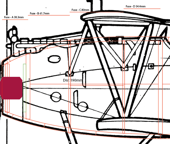
So, to start, I have a blueprint, I have some steps that I've measured out into segments, I have the cross-sections between these segments and from those I have the circumference of the trailing and leading edges of each segment..
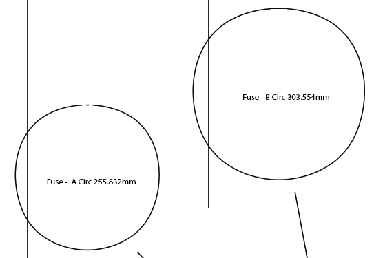
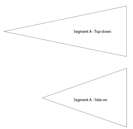
So, I have all my lengths figured out. The issue now is drawing the shape. If I draw the leading and training edges straight and parallel, then I end up with a piece that can only be bent into a straight cylinder that slopes at the join, rather than a cone. Using the technique linked above, I drew triangles that would help me gauge the 'slope' of the cone I wanted to form:
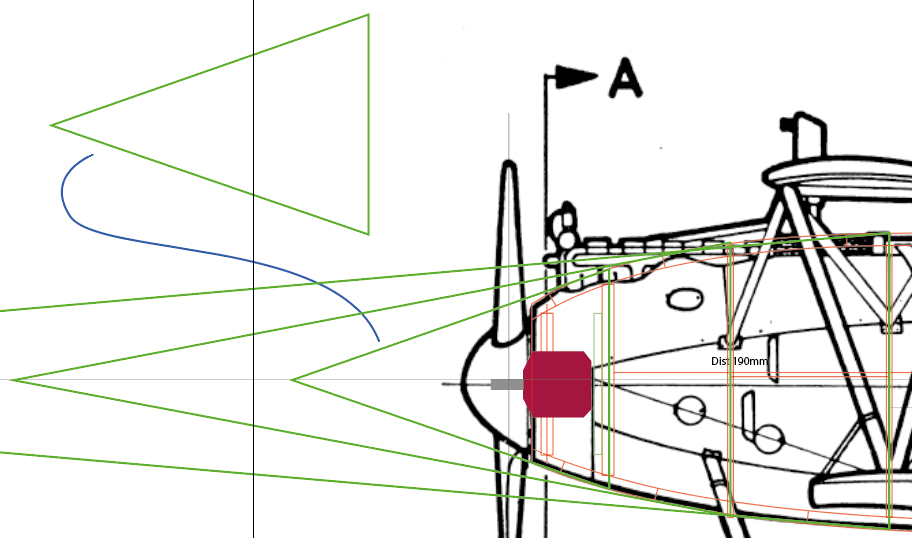
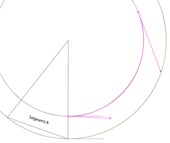
Here's another problem - the plane I am desinging is taller than it is wide. So I've ended up with two reference triangles for each segment. I decided on picking the shortest one as it has the steeper slope and it's probably easier to squash a steeper slope to shallower angle than going the other way around. Back to the method linked above, I drew circles centered on the 'apex' of the 'cone', one reaching the trailing edge and then another reaching the trailing edge minus thickness of the segment. As I know of no tool for 'Adobe Illustrator, please cut me a slice of this circle which will have the same arc but be exactly 255mm long', I just drew another line over it then stetched and bent it until it was within 1mm of the desired length.
I tried this again with the second segment and now I have a couple of shapes... Am I confident in them? Nope! 😂I mean, the desired thickness of segment B, if fitted in the middle of the two lines, apparently places these lines too far apart for that same distance to link them at the ends and so I'm going to get a crooked cone. This could just be the result of tolerance stack and when it comes to working in real life, I will be sanding out such imperfections anyway, but at this stage, am a little unsure if I am going down the right path.
So, in case I am about to waste a lot of time, I was wondering if anyone had any methods for preciecly measuring out a fuselage piece, or if the only way forward from here is trial and error.
Before I delve into what I've tried, I want to mention an important requirement; I do not want to rely on software where I build a 3D model and then 'unwrap' it into a 2D shape. I want a physical approach that will allow me to draw out plans using a pen, a ruler and maybe some string.
I did find a method used by sheet metal cutters for designing cones but, I find the instructions hard to follow. So many google results for 'How to flatten a cone' lead to how to do such a thing in Solidworks, that I'm having a hard time finding any other 'analogue' approaches to this problem.
So, to start, I have a blueprint, I have some steps that I've measured out into segments, I have the cross-sections between these segments and from those I have the circumference of the trailing and leading edges of each segment..


So, I have all my lengths figured out. The issue now is drawing the shape. If I draw the leading and training edges straight and parallel, then I end up with a piece that can only be bent into a straight cylinder that slopes at the join, rather than a cone. Using the technique linked above, I drew triangles that would help me gauge the 'slope' of the cone I wanted to form:

Here's another problem - the plane I am desinging is taller than it is wide. So I've ended up with two reference triangles for each segment. I decided on picking the shortest one as it has the steeper slope and it's probably easier to squash a steeper slope to shallower angle than going the other way around. Back to the method linked above, I drew circles centered on the 'apex' of the 'cone', one reaching the trailing edge and then another reaching the trailing edge minus thickness of the segment. As I know of no tool for 'Adobe Illustrator, please cut me a slice of this circle which will have the same arc but be exactly 255mm long', I just drew another line over it then stetched and bent it until it was within 1mm of the desired length.


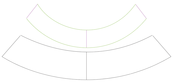
I tried this again with the second segment and now I have a couple of shapes... Am I confident in them? Nope! 😂I mean, the desired thickness of segment B, if fitted in the middle of the two lines, apparently places these lines too far apart for that same distance to link them at the ends and so I'm going to get a crooked cone. This could just be the result of tolerance stack and when it comes to working in real life, I will be sanding out such imperfections anyway, but at this stage, am a little unsure if I am going down the right path.

So, in case I am about to waste a lot of time, I was wondering if anyone had any methods for preciecly measuring out a fuselage piece, or if the only way forward from here is trial and error.


