
You are using an out of date browser. It may not display this or other websites correctly.
You should upgrade or use an alternative browser.
You should upgrade or use an alternative browser.
The CyberHex
- Thread starter Cyberdactyl
- Start date
Cyberdactyl
Misfit Multirotor Monkey
Oh yes, I have seen props mounted upside down. Just browse rcgroups forums for many examples.
However, 100% TCE is theoretically impossible since there must be a motor or mechanical power transfer mechanism either under or over the thrust column and/or a connecting structure.
But hey, please understand, I'm not trying to be self-righteous by saying plate-type MRs are crap, I had one and could very well have another if the price was right. What I'm aiming for is to present an ..awareness.. of just how much loss of lift and flight time is sacrificed by having an insouciant attitude towards TCE in general.
I may make a practical and empirical demonstration video showing just how much lift and flight time a plate-type MR is wasting by having the boom loaded with wiring and ESCs turned flat.
We're seeing ultra low TCE now in the current popularity of the mini-FPV quad. The ESCs and booms on those mini's are basically as wide as a 450-550mm quad, but with the much reduced planform thrust area of a 3.5-5" prop. Essentially reducing the TCE down to around the mid to upper 70's.
Cyberdactyl
Misfit Multirotor Monkey
Got my sheets of G10 today.
I'll start on the next version of an ultimate TCE MR this weekend. I say multi-rotor because I'm interested to do a small tricopter, but with 1300KV motors using 0847 props. Sort of a sport FPV mini tri. At the same time, I'm also tempted to take the electronics from the current hex and reproduce it, but increasing the TCE by a good 4%, or cutting the current obstruction in half. But it's the mass reduction that would/should make it an entirely new flyer. It would save me hours of work, and I'm not at all happy having wires stacked and taped on the trailing edge, it just looks awful. Works as intended, but ugly.
But I have definitely decided to do as I mentioned in the Cyber HEX article and sandwich a 2.5mm plate of G10 between two plates of 0.35mm of G10. Below is a cross section of a boom. The red lines will be epoxied 18g/m2 glass fiber cloth for some enhanced rigidity, which replaces the epoxy "tube" I did for the plywood booms.
The two short black lines at the bottom will be thin strips of the 0.35 under the motor wires to hold them up and in position, but low enough so the wires don't flair the plates. Silicone 16g wire is almost exactly 2.6mm and should compress nicely and fit nice and snug.
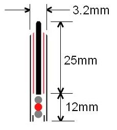
This design should easily beat even a polished 12mm carbon fiber round tube. And if I can keep the mass under control, it should be noteworthy. It can't match a CF tube, simply because CF mass is only around 75% that of G10 and the cross section of materials is more than a tube. I DO realize beating a CF boom in TCE, that is already in the mid 90's, is taking it to the extreme. . .
I'll start on the next version of an ultimate TCE MR this weekend. I say multi-rotor because I'm interested to do a small tricopter, but with 1300KV motors using 0847 props. Sort of a sport FPV mini tri. At the same time, I'm also tempted to take the electronics from the current hex and reproduce it, but increasing the TCE by a good 4%, or cutting the current obstruction in half. But it's the mass reduction that would/should make it an entirely new flyer. It would save me hours of work, and I'm not at all happy having wires stacked and taped on the trailing edge, it just looks awful. Works as intended, but ugly.
But I have definitely decided to do as I mentioned in the Cyber HEX article and sandwich a 2.5mm plate of G10 between two plates of 0.35mm of G10. Below is a cross section of a boom. The red lines will be epoxied 18g/m2 glass fiber cloth for some enhanced rigidity, which replaces the epoxy "tube" I did for the plywood booms.
The two short black lines at the bottom will be thin strips of the 0.35 under the motor wires to hold them up and in position, but low enough so the wires don't flair the plates. Silicone 16g wire is almost exactly 2.6mm and should compress nicely and fit nice and snug.
This design should easily beat even a polished 12mm carbon fiber round tube. And if I can keep the mass under control, it should be noteworthy. It can't match a CF tube, simply because CF mass is only around 75% that of G10 and the cross section of materials is more than a tube. I DO realize beating a CF boom in TCE, that is already in the mid 90's, is taking it to the extreme. . .
Looking forward to seeing it.
One thing I keep wondering though...while the TCE may be better than a tube is the overall efficiency really better. Those big flat surfaces present a lot more surface when moving laterally or yawing than a tube does. If all you're doing is hovering then yeah, max TCE will win out. But I wonder if in actual flying conditions how much the tradeoff is.
I've been seriously considering making airfoil shaped booms for a V-tail as my next build...but keep thinking a tube is still the best overall due to the 3 dimensional nature of the way I fly which includes very little hovering and lots of moving in every direction possible (sometimes even the direction I mean to be going!)
Cyberdactyl
Misfit Multirotor Monkey
Yes, you are right. However, my contention is, there is an extremely fast down-rush of air 100% of the time when flying. Making the boom as efficient as possible for that constant, unrelenting variable is the most important.
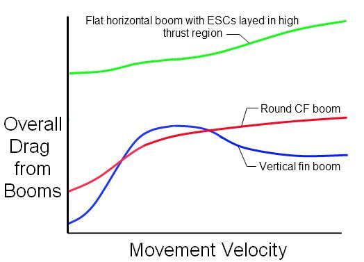
When moving laterally at a moderate speed, I agree totally, there will be increased drag for the vertical fin. It's exactly in that middle region of movement vertical fin booms loose out. At upper end speeds, where the multi-rotor tilts more and more in the direction of flight, whether it be straight up, or laterally over the ground, is where a vertical fin boom's efficiency again enters a region of best orientation possible.
Below is my loose empirical estimate of what occurs. As you can see, the round boom maintains the smoothest drag curve throughout.
adamd
skunkworx hobbies
I wonder if the fin type boom could regain more efficiency in forward flight by acting like a wing bringing down some of the total a/c weight on the motors. In your graph the drag on fin type booms deceases with greater forward speed due to a larger tilt angle exposing less flat surface to the air stream. now at a high tilt angle with forward speed would the booms not create a small amount of deflectional lift, such a shockflyer in high alpha?. now i'm not suggesting a tilt rotor type, removing all lifting force off the motor during forward flight but a combination of aerodynamic lift and thrust lift hopefully regaining some potential energy stored in your momentum.
Cyberdactyl
Misfit Multirotor Monkey
N i n j a - P i n w h e e l !
Cyberdactyl
Misfit Multirotor Monkey
Sunday I went flying at Dix field in Raleigh. It's open spaces there , and was able to get some 200-250 meter runs over the ground close to wide open. The day was in the low 80's. On 4S, it did get the F20 ESCs toasty, maybe 115F.
I've cut the obligatory 12mm x 20mm hole. Makes all the difference. When I land after pushing it hard, it's only slightly warm. I'm guessing 105F.
I've cut the obligatory 12mm x 20mm hole. Makes all the difference. When I land after pushing it hard, it's only slightly warm. I'm guessing 105F.
Cyberdactyl
Misfit Multirotor Monkey
Ok, I know some may think I'm beating a dead horse, but I want to show the beast is alive and well and continuing to be shrug off.
I wanted to empirically check to see if I was making too much of a big deal out of the need to convince the hobby that loading the boom down with unnecessary width was as detrimental to efficiency as my calculations indicated.
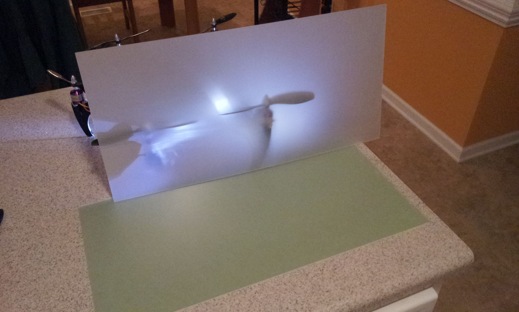
This afternoon I set up a crude, but very revealing experiment to show just how much energy is wasted and designed into many multi-rotors. I'm not going to spend the time and combine the three conditions into one video, but I have included all three below.
My setup: I clamped my hex down, with a boom and motor suspended over open space. I laid the mockup booms down on a gram scale, let the scale zero-out the mass, put two nails on either side of the booms as guides and evened out the distance on either side of the scale to nullify any fulcrum mechanical advantage. I then tested three booms by running the motor up to 50% throttle, (more or less hovering power for the hex).
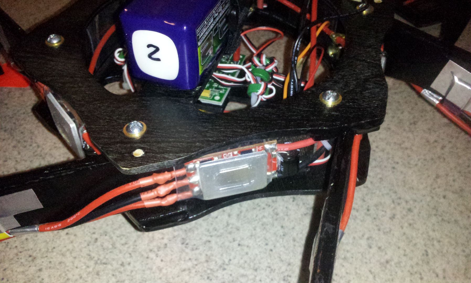
The first is the standard 10x10mm carbon fiber HK tube. The second is a 9mm dowel rod, (I don't have any round CF). And last, a standard ESC laid flat on the 10x10mm square CF tube directly in the highest area of thrust. Each of these are laid under 0847 CF prop being spun by a 1300KV motor. (see the pics below).
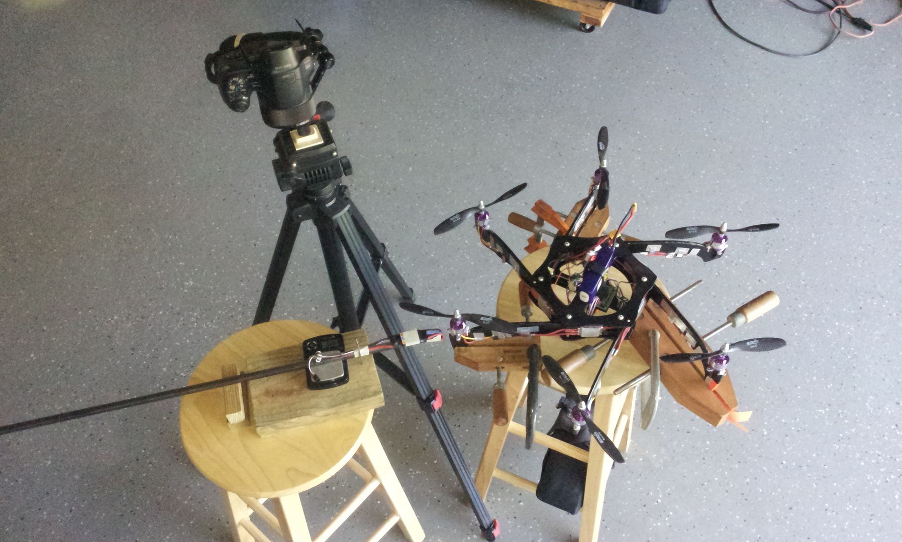
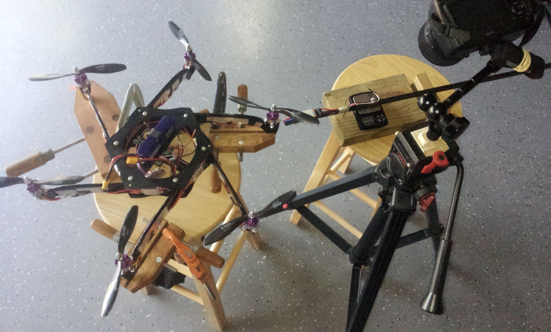
The results are as revealing as I imagined. If using a quad, multiply the wasted gram force by 4, for a tricopter by 3, etc. The setup got shifted and/or moved slightly before I started the motors, so any mass indicated on the scale needs to by taking into account, however it is inconsequential in any case by the obnoxious amount of wasted energy. Remember. . . this reflects directly to mass you COULD carry, and/or thrust being trashed by having an inefficient TCE boom.
10x10mm Hobby King Square Carbon Fiber Tube
9mm Wood Dowel
10x10mm Carbon Fiber Tube with a HK F20 Laid Flat
I wanted to empirically check to see if I was making too much of a big deal out of the need to convince the hobby that loading the boom down with unnecessary width was as detrimental to efficiency as my calculations indicated.
This afternoon I set up a crude, but very revealing experiment to show just how much energy is wasted and designed into many multi-rotors. I'm not going to spend the time and combine the three conditions into one video, but I have included all three below.
My setup: I clamped my hex down, with a boom and motor suspended over open space. I laid the mockup booms down on a gram scale, let the scale zero-out the mass, put two nails on either side of the booms as guides and evened out the distance on either side of the scale to nullify any fulcrum mechanical advantage. I then tested three booms by running the motor up to 50% throttle, (more or less hovering power for the hex).
The first is the standard 10x10mm carbon fiber HK tube. The second is a 9mm dowel rod, (I don't have any round CF). And last, a standard ESC laid flat on the 10x10mm square CF tube directly in the highest area of thrust. Each of these are laid under 0847 CF prop being spun by a 1300KV motor. (see the pics below).
The results are as revealing as I imagined. If using a quad, multiply the wasted gram force by 4, for a tricopter by 3, etc. The setup got shifted and/or moved slightly before I started the motors, so any mass indicated on the scale needs to by taking into account, however it is inconsequential in any case by the obnoxious amount of wasted energy. Remember. . . this reflects directly to mass you COULD carry, and/or thrust being trashed by having an inefficient TCE boom.
10x10mm Hobby King Square Carbon Fiber Tube
9mm Wood Dowel
10x10mm Carbon Fiber Tube with a HK F20 Laid Flat
FinalGlideAus
terrorizing squirrels
Certainly not flogging a dead horse with these experiments. I find them very interesting. I do think there is more to it than the test you just did though.
To be very conclusive you would need to attch one of your hex style arm to some scales like it's done for a thrust test and measure the trust. Then add a "mock" flat arm to the structure and re-test the thrust. This would give a true figure in real world circumstances.
To be very conclusive you would need to attch one of your hex style arm to some scales like it's done for a thrust test and measure the trust. Then add a "mock" flat arm to the structure and re-test the thrust. This would give a true figure in real world circumstances.
Cyberdactyl
Misfit Multirotor Monkey
Yea, I would have done an edge-on plate, but I didn't want to further construct a jig to hold it vertical while insuring that I wasn't introducing any mechanical advantage error.
I think the stark difference between the 10x10mm square boom and the dowel in contrast to the ESC turned flat is enough to show the insane wasted lift capability of not being concerned with what's blocking the thrust.
Then again, there's shrugging off TCE as opposed to not having a clue. . .

I think the stark difference between the 10x10mm square boom and the dowel in contrast to the ESC turned flat is enough to show the insane wasted lift capability of not being concerned with what's blocking the thrust.
Then again, there's shrugging off TCE as opposed to not having a clue. . .

andybenton
NERD!!!! :)
Have the test results been posted? Maybe I'm just slow, or because I'm viewing on a phone, either way I can't see any of the data, just the photos of the rig.
FinalGlideAus
terrorizing squirrels
Lol, I kinda want to fly that Y6. It looks fun and crazy all at that the same time
Andy, sometimes you can't view them on your phone.
Andy, sometimes you can't view them on your phone.
FinalGlideAus
terrorizing squirrels
Right so for the past few days I've been playing with BLheli and having some success and some backwards steps. After frying an esc doing a stupid test I needed a break and Cyber's last test got my brain cells jumping around. So I built a thrust tester for two reasons. Firstly I wanted to test cyber's ideas in a real world situation and secondly I needed one anyway and needed an excuse to build it. I gave myself an hour to build it out of what ever scraps I could find. Well it took an hour and a half so I'm not upset. It's made of ply and old Bat Bone arms
Anyway, I put an NTM 2826 1200kv on 3s running a 9x4.7 on and with the test rig sporting a 12mm wooden square arm and it pulled 885grams. I then added an old ruler flat to the arm which was 42mm wide. The motor then pulled 850grams thrust. So that's 35grams lost thrust for increasing the arm width nearly 4 times. In other words, doubling the arm width to 24mm which is about the width of an F20a and making it that width all the way along the arm only lost around 8-10 grams of thrust. That test indeed proves to me that there is thrust lost to increased TCE, but only about 1% of the total thrust when looking at the average Multicopter square booms.
The test was just a quick one to confirm my suspicions but happy to do a proper test with pictures if you need it.
This idea is so awesome, that you should expect to see a copy of it on the HK site soon!
Cyberdactyl
Misfit Multirotor Monkey
Thanks for finding the interest and time to explore the issue FGA.
I do think my setup may exaggerate the problem. While I do get a force pushing on the F20 boom at over 400g while pushing air at 50% power, it does seem odd to expect that much is exerted on the craft.
But at the same time, your setup also seems very low, especially since the area being increased is in the worst area possible (as opposed to under the motor) The area of a 9" disk is 63.6 sq in. Your 'benchmark' thrust was 885g with ~2sq in. of obstruction. Your drop in thrust was 35g after increasing the obstruction by ~5.2 sq in.
If we explorate and extend that out, we can cover the the entire disk with ~12 more, and then have a suggestive loss of thrust of ~420g. However, that essentially leaves 465g of effective thrust with an entirely blocked disk. . .
What trying something like a simple hover in a garage to minimize wind effects with the cyberhex as it is, and then add some pieces of flat material progressively larger under the props and repeat the test to see how the times compare.
It may not be quite as scientific - but it would produce numbers that mean more to the general reader (flight times) and shouldn't be that difficult to setup.
You could potentially even rig some kind of harness that keeps the quad in position so it's just using it's power to maintain a hover not correct positioning.
Similar threads
- Replies
- 1
- Views
- 116
- Replies
- 3
- Views
- 333
- Replies
- 2
- Views
- 770