A Depron Seagull

quorneng

Master member
Plane Print have for sale the print files for a 1.5m span Seagull both as a glider and EDF powered. The majority of it is printed in LW_PLA.
It certainly seems to fly but I was a bit concerned at the all up weight of the EDF version at 560g given it is using just a 40 mm EDF. Some of the EDF versions made ended up at over 600g.
I have to admit it does look very realistic making full use of sweeping shapes possible with printing. It using elevons and a rudder tail so is in effect a flying wing.
In the past I have built a couple of small scale planes using 2mm Depron. Both came out below 250g. :eek:
A 600mm span DH Venom with a 40 mm EDF. 202g
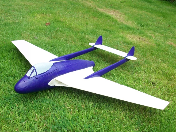
13Aug17.JPG

A 800 mm EE Canberra with 30 mm EDFs. 248g.
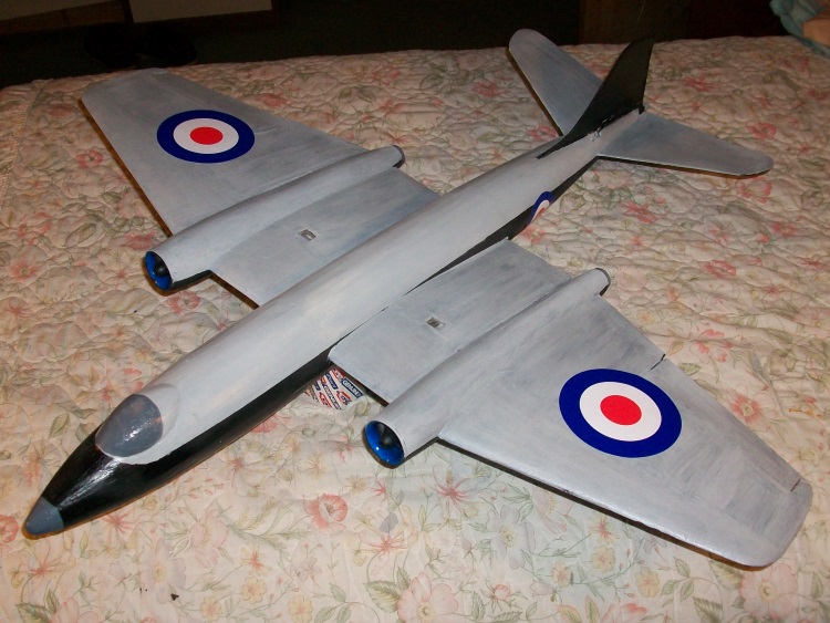
Complete4.JPG

Would it be possible to do the same to make a Seagull?
A 3 view drawing of a possible layout.
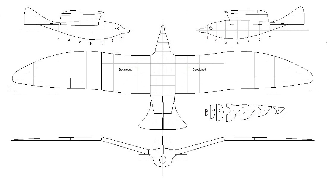
3View1.jpg

Likely to be a bit smaller than the Plane Print version at only 1.2m span but then it should only be half the weight.;)
A bit more of an 'aeroplane' than a flying wing with an elevator and differential ailerons but a fixed fin. A configuration I have used in many EDFs although in this case the tail 'volume' will be very limited. The only printed parts would be the EDF inlet and exhaust ducts.
I came across a very nice QX 30 mm EDF that is claimed to deliver over 200g on 3s.
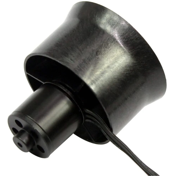
30mm EDF.jpg

It only weighs 21g so as long as the ducting does not absorb too much thrust and the 250g limit is achieved it should do.
The next task is some 'test' ducts to find out what actually happens.
There is no rush as the UK is moving into winter and this is quite likely to be a 'tricky to fly' lightweight.
 
Last edited:

quorneng

Master member
The first task is to print a typical inlet and exhaust duct configuration to find out what effect it might have on the EDF's performance.
At these small sizes I though the use of LW-PLA might give a useful weight saving.
My initial though was to mount the EDF close to the exhaust. The longer and bigger inlet duct (area 1.2 the FSA) with a top inlet just ahead of the wing so it would be completely invisible when in the air.
the full duct placed in the approximate position over the body half shell.
HalfShell3.JPG
 

quorneng

Master member
Not very scientific but the 30 mm EDF and duct does seem to work.
My usual test is to see if the EDF can blow the door shut but then it only a 30 mm running on a 3s. ;)

I do have a number of worries about using a 'top' inlet. First the big diameter inlet duct takes up a lot of space just where the battery is likely to need to go. The inlet itself creates a significant proportion of the thrust but with it on the top means it will tend to lift the nose when under power. Finally such an inlet would get virtually no ram pressure benefit from the planes forward motion.
A more conventional bifurcated wing root inlet although more difficult to make might be a better option.
We shall see.
 
Last edited:

quorneng

Master member
The first half body shell modified to have a wing root inlet.
RootInletX.jpg

The actual duct may be less efficient than the simple top view tube but it should make up it by ram air pressure when in flight.
The EDF is moved forward to match the Depron planked inlet
RInletEDF1.JPG

It looks a better arrangement but whether it will fly is another question.
 
Last edited:

quorneng

Master member
The above picture had a 15% restriction in the exhaust duct to achieve nearer to the FSA. This proved to have no thrust benefit whatsoever so a simple parallel duct was substituted.
With the limited space available so thought was given to the layout of the 'electrics'
Layout1.JPG

The 20A OPTO ESC is small and light enough but it does require a separate UBEC so the total weight saving is limited although installing two small items is easier than a bigger one piece ESC and BEC.
The intended LiPo is a 450 mAh 3s.
It is all quite a tight fit as well as having to guess where the CofG might need to be.
Made a start on the wings.
Each wing rib is printed in LW-PLA. It is about 1/2 the weight of using normal PLA
LW-PLARib.JPG

A single surface with a 3mm 'truss' bracing.
The full set of ribs.
RibsL&R.JPG

There is only one design of rib as all the smaller ones were created ones using CURA's scaling feature.
Next is to cut out the top and bottom Depron skins.
 

quorneng

Master member
As everything is going to be built it (except the LiPo) to the body it means all the electrics and servo have to be installed before the two halves are glued together. This means the wings have to be built and completed and the servo cable run through them before they are glued onto each body half.
The wing is built in 4 separate pieces.
WingParts.JPG

A 2mm Depron lower skin, the ribs glued on followed by the top skin. Each skin is manually manipulated to give close to the correct shape then clamped & pinned in position whilst the glue dries.
The 'joining' ribs have been inclined at the appropriate angles to give the gull wing.
Only held together with tape at this point just to get an idea of what it looks like.
GullWing.jpg

Next the aileron is cut out and the servo is installed through the lower skin and its extended wire run through the wing and into the body. Only then can it be all glued together.
WingLh.jpg

The crude jig is to ensure the other wing ends up with similar gull angles!
There is no reinforcement. The wing skin providing all the strength and stiffness. The wing joints are simply skin to skin butt joints. The Technicqll foam safe glue seeps into the Depron and sets rock hard after 24 hours. The joint is as strong as the foam, well nearly.
The half wing, including the servo weighs just 28 g.
Happy it can all be put together its on to the other side.
 

quorneng

Master member
It is now more or less complete with a very light wash of thinned water based paint, Dove grey wing top, white elsewhere.
Complete2.JPG

Just the black wing tips to do.
A proper Seagull 'hooked' beak and that is a picture of an seagull's left eye!
Complete3.JPG

With a reversed one on the other side.
1210 mm span. It weighs 181 g ready to go but not flown yet. It will heed some seriously calm weather.
 

Mr NCT

Site Moderator
It is now more or less complete with a very light wash of thinned water based paint, Dove grey wing top, white elsewhere.
View attachment 232616
Just the black wing tips to do.
A proper Seagull 'hooked' beak and that is a picture of an seagull's left eye!
View attachment 232617
With a reversed one on the other side.
1210 mm span. It weighs 181 g ready to go but not flown yet. It will heed some seriously calm weather.
It's a beauty, can't wait to see video of flight!
 

quorneng

Master member
Flight testing has proved rather dramatic with just about everything wrong!
First the CofG needed to go quite a bit forward and the elevator proved to be impossibly sensitive where as the ailerons were the complete opposite.
Apart from a longer nose the othe change was a twin fin!
TwinFin2.JPG

Done primarily to increase the rigidity of the tail surfaces with a small elevator between them.
The other big change was a down turned exhaust nozzle as it exhibited rather extreme power on pitch up. Sort of down thrust.
30degLong.JPG

There is now is a short flight video.
The video stopped recoding at 1:22 so the section demonstrating its excellent glide is lost.
Still need a bit more adjustment but it definitely flies.
 

Inq

Elite member
I've never seen Depron in the flesh... is it similar to taking the DTFB and removing the paper on both sides? Meaning is it a pliant material or is it more rigid/brittle like polyurethane type foams?

Because... when you said you weren't getting enough aileron authority, the first thing that crossed my mind was to try wing warping. It would give you much more functional aileron and be more cosmetic eliminating the exposed servo and separate aileron.

I was exploring a design for a sailplane using it. Something like this. The twist is exaggerated... I'd imagine 3 or 4 degrees would be ample.

Wing Warping.png
 

Inq

Elite member
That's a very cool idea, Inq. Did you get to any physical testing?

It was old technology when the Wright Brothers were using it! ;)

... but to answer your question... no. Out of the six planes and the propeller projects I've currently got going, I haven't gotten back to this.

In actuality, for my sailplane project, I was/am looking at a flying wing... and rigid version of it. Instead of warping, it simply rotates... here is the plan shape of the wing.
Concept.jpg


... and here is the CAD of the mechanism. This shows the conceptual design. The wheel inside the vertical stabilizer has a shaft and outer portion of the wing is rigid and the entire outer section turns as one. It was going to use braided fishing line running down the wing to turn the wheel. All 3D printed.
Elevon Base.png


The wing warping came to me when I saw @quorneng 's Gull... thinking it looks great! I was just thinking that if Depron is flexible enough warping could be achieved and hide all the aileron mechanism. It doesn't take much twist/area when the entire foil acts as the control surface. Aka... flying elevons on all modern jets.

Then my psychosis took over and went to a Peregrine Falcon with wings that tuck (aka F-14). In my younger days, it was fast cars fast, fast boats, fast women and now... I settle for fast artificial birds. :ROFLMAO:
1674845108303.png
 

quorneng

Master member
The original true Depron was remarkably rigid & fairly brittle. Not dissimiler to lightweight balsa but only 1/5 the weight. In fact Depron was a sandwich of a thin dense and shinny layer with a softer core. Ideal for modelmaking but rather expensive to produce. Its smooth surface meant with care it needed virtually no finishing. Unfortunately the sandwich effect meant little to the main user, the building industry, so production stopped. The current Depron no longer has a sandwich structure but is still a bit denser and stiffer than foam board with the paper removed.

I think yu will find there was good reason why wing warping or all moving wing tips did not last long on full size planes. Near the stall it promotes the stall starting at the tip. Exactly the opposite of what you want.
 

Inq

Elite member
I think yu will find there was good reason why wing warping or all moving wing tips did not last long on full size planes. Near the stall it promotes the stall starting at the tip. Exactly the opposite of what you want.

I think your gull is fantastic. I wish I could do the work you are capable. But I can't stand idle when such an unsubstantiated statement as you have made and expect it to be taken purely on your casual words. It is not self evident to this aerospace engineer as you imply it should be to every one of us. Wing warping and flying tips are way two different things. I will address your comment specifically to each:

Wing warping died because wings needed to be structurally stronger to keep them from folding up... especially once cantilever monoplanes came into vogue (circa 1918). It was impossible to make them strong in bending, yet soft enough to still be able to twist... WITH technology of 1918 to early 2000s.

Flying wingtips - Even this is broken up into two aspects:
  1. Flying Wingtip as I was approaching in my sailplane design (above) being a rigid separate piece - To my knowledge it was only worked on by NACA back in the 1930's. This article describes in strait-forward language some of the issues with the design -http://acversailles.free.fr/documen...ernes/Ailerons/Facts_on_wing-tip_ailerons.pdf. Most of the issues are based on technology and design capabilities of the 1930s.
    1. The issues that are still valid are valid at full-size Reynold's numbers. At model scale Reynolds numbers, many of them go away.
    2. A common logic example - In a stalling condition, the pilot is likely trying to lower the offending wing to get it out of a stall AOA. An aileron will be in the turbulent flow of the stall and be totally useless... preventing the pilot from recovery. However, the "flying tip" could still be lowered by the pilot and be out of the stall range... in controlled air and be able to pull the wing back down. In all likely hood the "flying tip" would be a more recoverable design.
    3. The most offending issue was flutter. If you move the pivot point too close to the center of lift, the flying tip starts to flutter. THE ONLY SOLUTION NACA STUDIED was to move the pivot point forward. They considered this unsuitable ONLY because of high control forces on the pilot. This was in 1930 before using hydraulic actuators on control surfaces became standard OR even simple flutter mitigators like simple "shock absorbers".
    4. IOW... I know of no 21st century studies of such designs. Maybe you do... please supply references. I'll be glad to be proven wrong.
  2. Aerolastic Tailoring as I was trying to describe with the flexible torqued gull-wingtip tip version.
    1. Note - that it solves all the issue described in the paper referenced above.
    2. In fact I am aware of several recent studies (this century) using aeroelastic tailoring using composite material wing skins that go one step further than I purported above. They use internal hydraulics to change the shape of the AIRFOILS. The entire wing's chamber could be changed from zero to positive to negative, IOW... the interceptor could be flying along with a thin, zero chambered wing, low drag wing (blue)... and be jumped by an enemy. The left wing (THE ENTIRE WING) could change to a high-lift chambered wing producing 20,000 pounds of lift more than the cruise wing... while at the same time the right wing (green) does the opposite and produces 20,000 pounds of negative lift. Guess what happens! And those shape changes happen in milliseconds.
    3. On the plus side, no human aircraft (or even missile) could keep up with it. On the down side no human ever and no current airplane structure can handle the G forces.
    4. Guess why the US (and others) are developing drones. The days of Air Force and Naval aviators are numbered.
Untitled.png
 
Last edited:

mastermalpass

Master member
ItThen my psychosis took over and went to a Peregrine Falcon with wings that tuck (aka F-14). In my younger days, it was fast cars fast, fast boats, fast women and now... I settle for fast artificial birds. :ROFLMAO:
View attachment 234160

Ornithopters are a really under appreciated model type, to me and I would like to take one on at some point. Maybe it's a kind of movement that is just not easy to translate through a controller, but I would love to have a model that as well as continuous flapping can also 'tuck' and 'flare' quickly like Swifts or Falcons.... As I wrote that, I was thinking of a very old video I watched, so I figured I'd do a quick search to see if anyone's had a go more recently. I am delighted to say someone has and it is amazing!


Not to hijack your thread of course, quorneng. Your gul not only looks great, but fixed wing will look natural too! Guls always seem to go as long as they can with out flapping, surfing on the winds and managing a loose hover like a kite (I say loose hover, 'cause the Kestral shows us what a true hover looks like). And it is also possible you make a friend in the sky; last year an inquisitive Seagul followed my mini P-51 pretty closely for a few laps before carrying on with its evening. 🙂
 
  • Like
Reactions: Inq

quorneng

Master member
Inq
I appreciate your points but ailerons were virtually universal on all biplanes and triplanes long before monoplanes became common. There may have been structural issues that favoured ailerons even on a fully braced biplane where little of the bending load is taken by the wing itself, but the fact remains that any form of wing warping can result in the critical angle of attack being achieved first towards the tip.

I agree entirely that wing camber changing can produce spectacular results, after all, modern airliners do it already with their complex flap arrangements but using it for the sort of manoeuvring you suggest is only possible with the benefit of full electronics controlling everything.

Mastermalpass
Amazing video indeed but I am left with the overriding impression of how inefficient it is compared to birds which use exactly the same process!
I fear we would have to develop much more sophisticated aerodynamics and control systems to stand much chance of equalling a birds performance.

I recall a video of a modern glass fibre glider (an example of the most efficient aerodynamics we have) in a thermal in South Africa. Circling round the pilot had two Vultures just off his wing tip matching both his speed and climb rate. Impressive enough except the Vultures were achieving this with their legs hanging down as airbrakes!