More progress on the rolling plotter/gantry...
I printed a couple of plates to mount the RPi and CNC controller boards on the back rail...
View attachment 172835
and then started working on the Z-axis.
After the "discussion" (I apologize if it was unwarranted, Mike... just me being "dense", I guess) about the various forms of belt-drive, I decided to see if I could make the entire machine be belt-driven. I came up with a smaller version of the Y-axis linear stage, to use as a Z-axis. As I don't ever expect to lift anything heavier than a laser, needle cutter, or a pen... I wanted to try using a very inexpensive 28BYJ-48 geared stepper motor that I had used on a couple of projects before. But first I needed to perform a well-known "unipolar to bipolar" conversion/hack on it (you cut a trace on the internal PCB and remove the 5th wire) to increase its torque and allow it to be driven with the little stepstick driver modules used on the other axes. Here it is in action...
I strained my brain to try to simplify the mechanism as much as possible and finally decided on a "shared carriage" assembly... where the Y-axis carriage plate is also the Z-axis carriage plate. So while the Z-axis carriage remains fixed in the Z-axis, the entire assembly moves up and down. I haven't added a tool mount yet but being V-slot extrusion, it's easy to attach stuff to it. The range of motion here is only about 55 millimeters and is limited by the lower end of the Z-axis hitting the spoilboard. I guess I'll eventually need to fashion 2x4 elevated guides for the trucks/tractors to run on if I have thicker materials I need to work on.
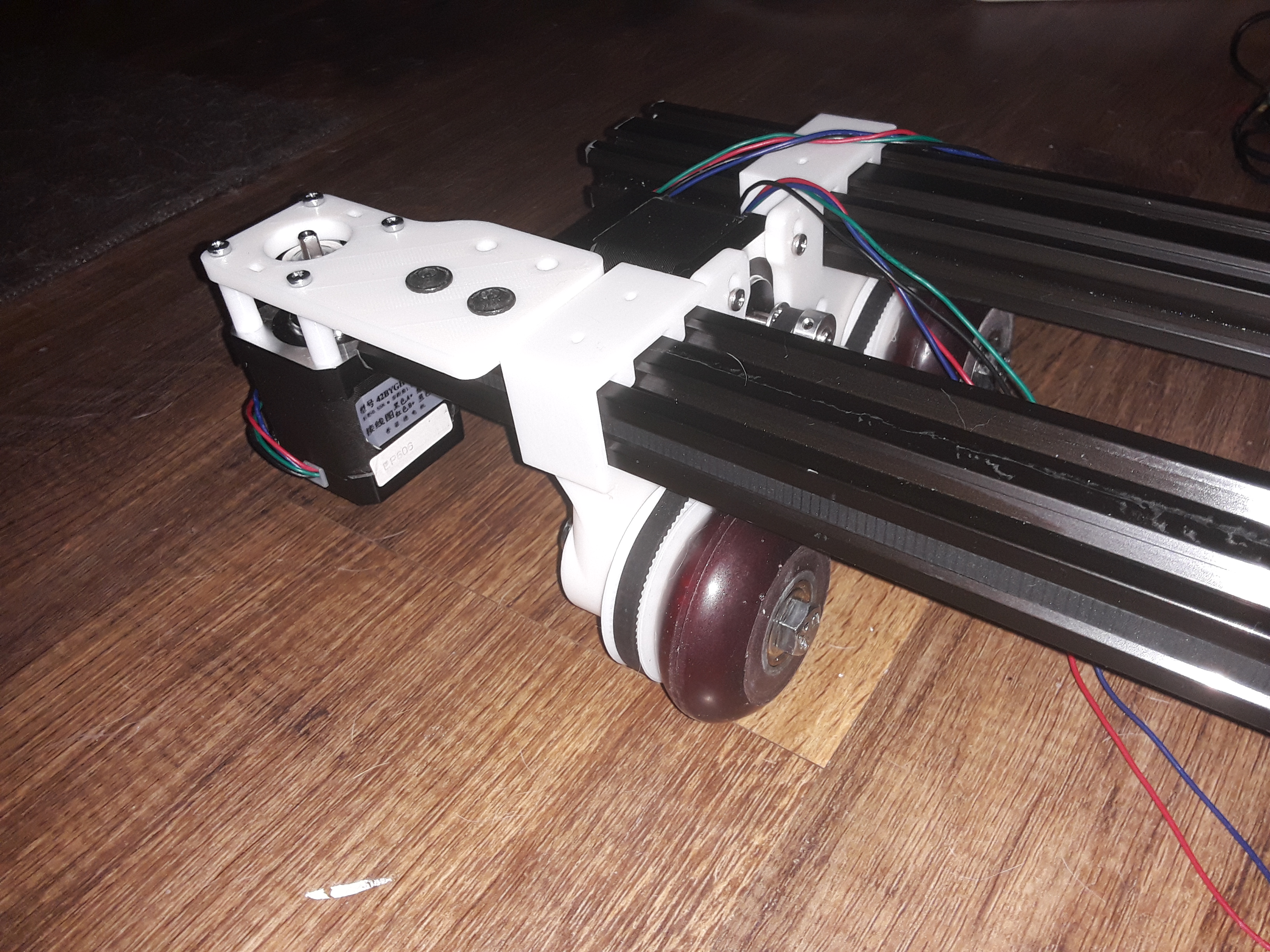
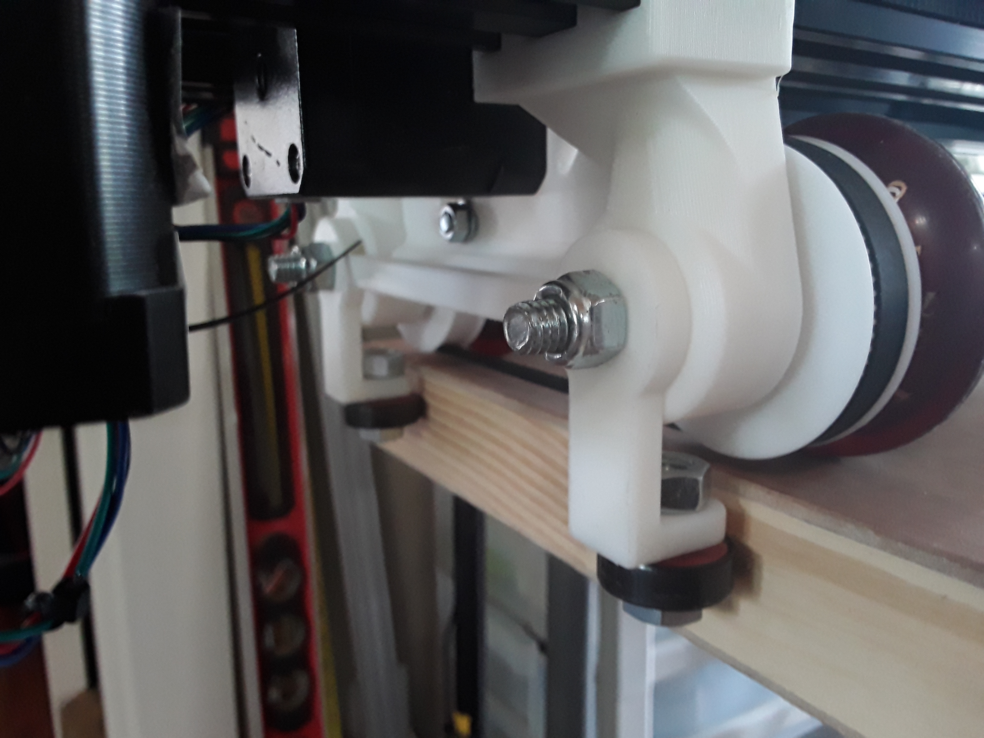
Here are detailed photos of the Z-axis assembly. The "hacked" (note the blue plastic piece just hanging...) 28BYJ-48 geared stepper motor, with IIRC a 20-tooth GT2 pulley...
View attachment 172836
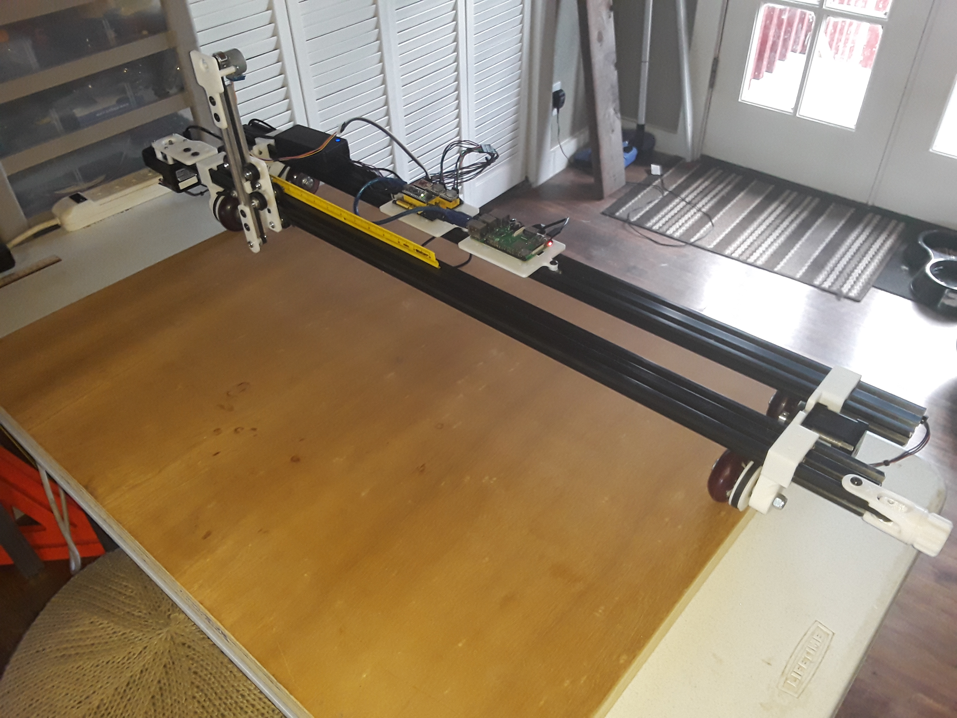
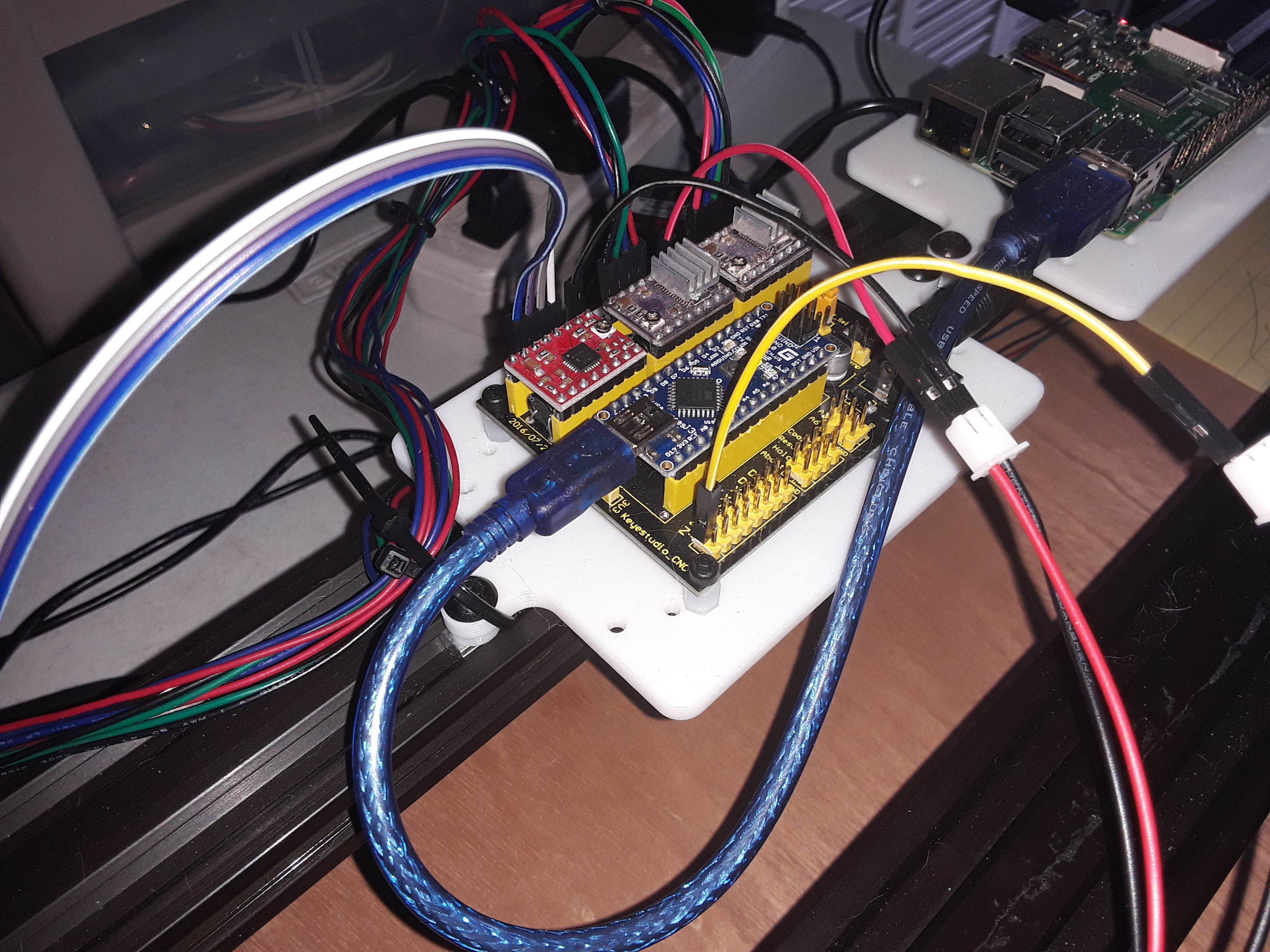
Back-side shot showing the stepper motor now driven by A4988 driver (had one sitting there). X and Y are driven with DRV8825 drivers and RPi-3B+ on the left...
View attachment 172837
Frontal shot of the Z-axis assembly and the shared carriage plate, with wheels front and back...
View attachment 172838
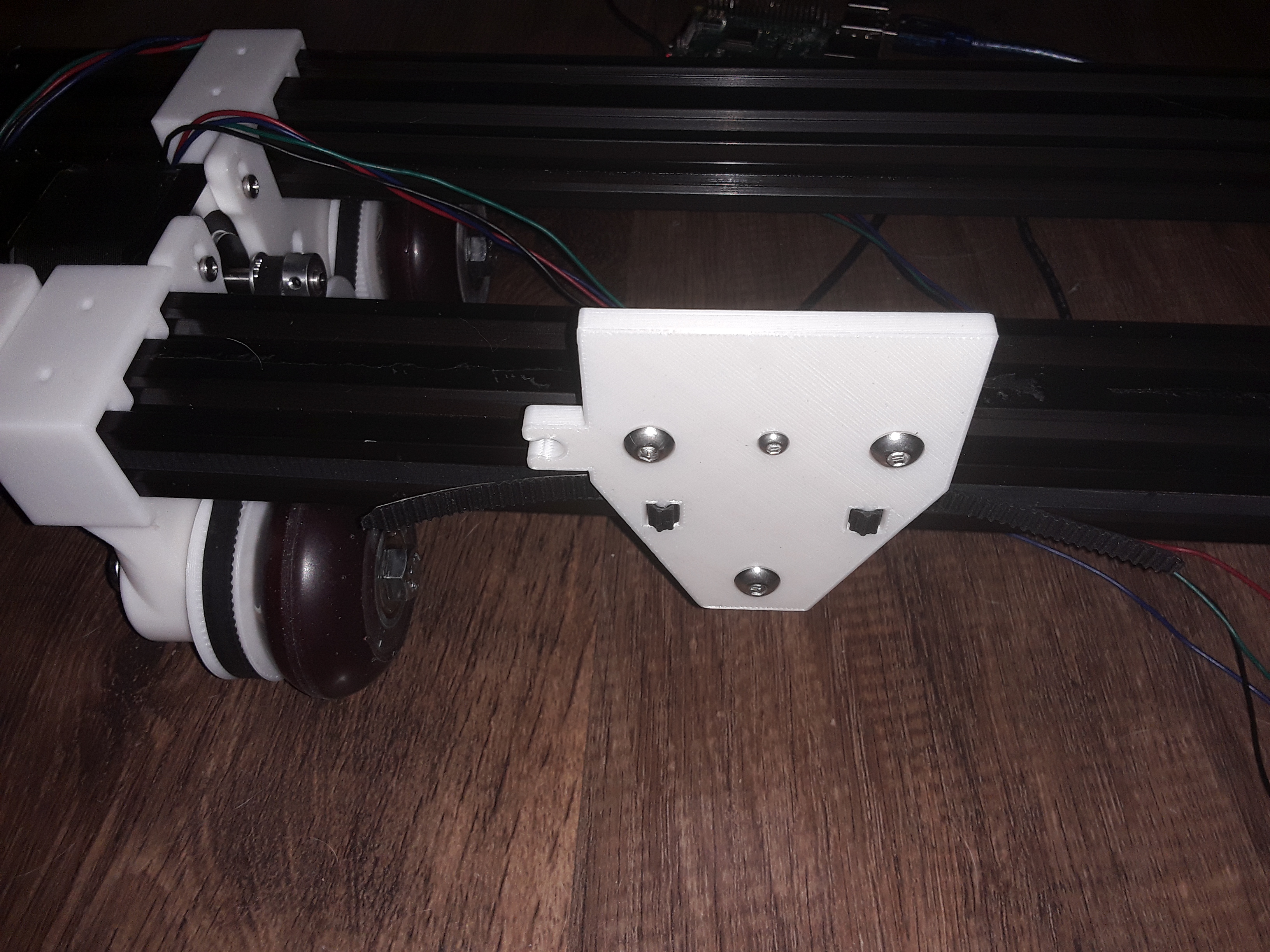
Z-axis "carriage" is just a little block capturing the belt ends and bolted to the Y-axis carriage...
View attachment 172839
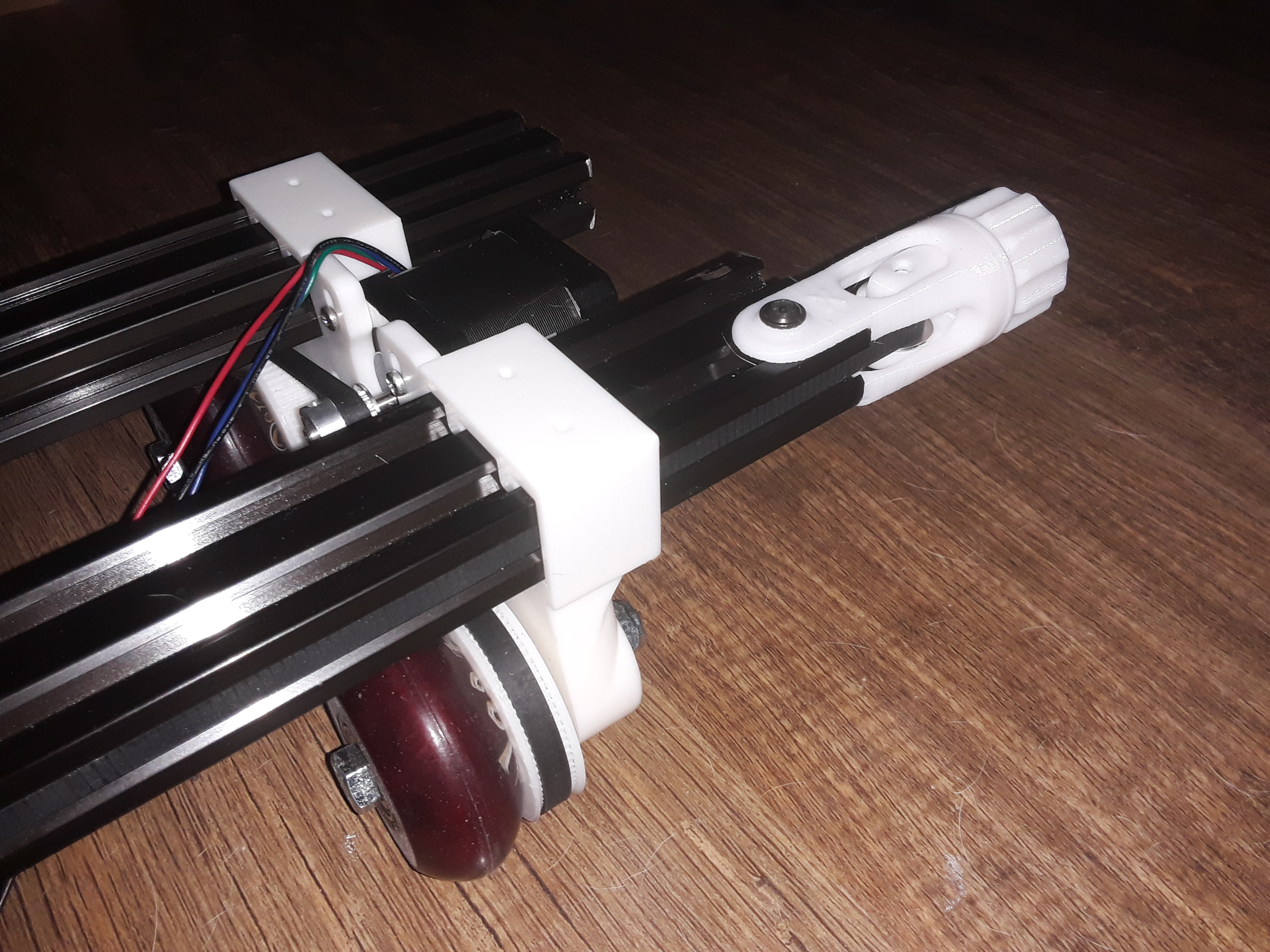
Another shot of the hacked 28BYJ-48 stepper motor and just enough belt clearance inside the extrusion...
View attachment 172840
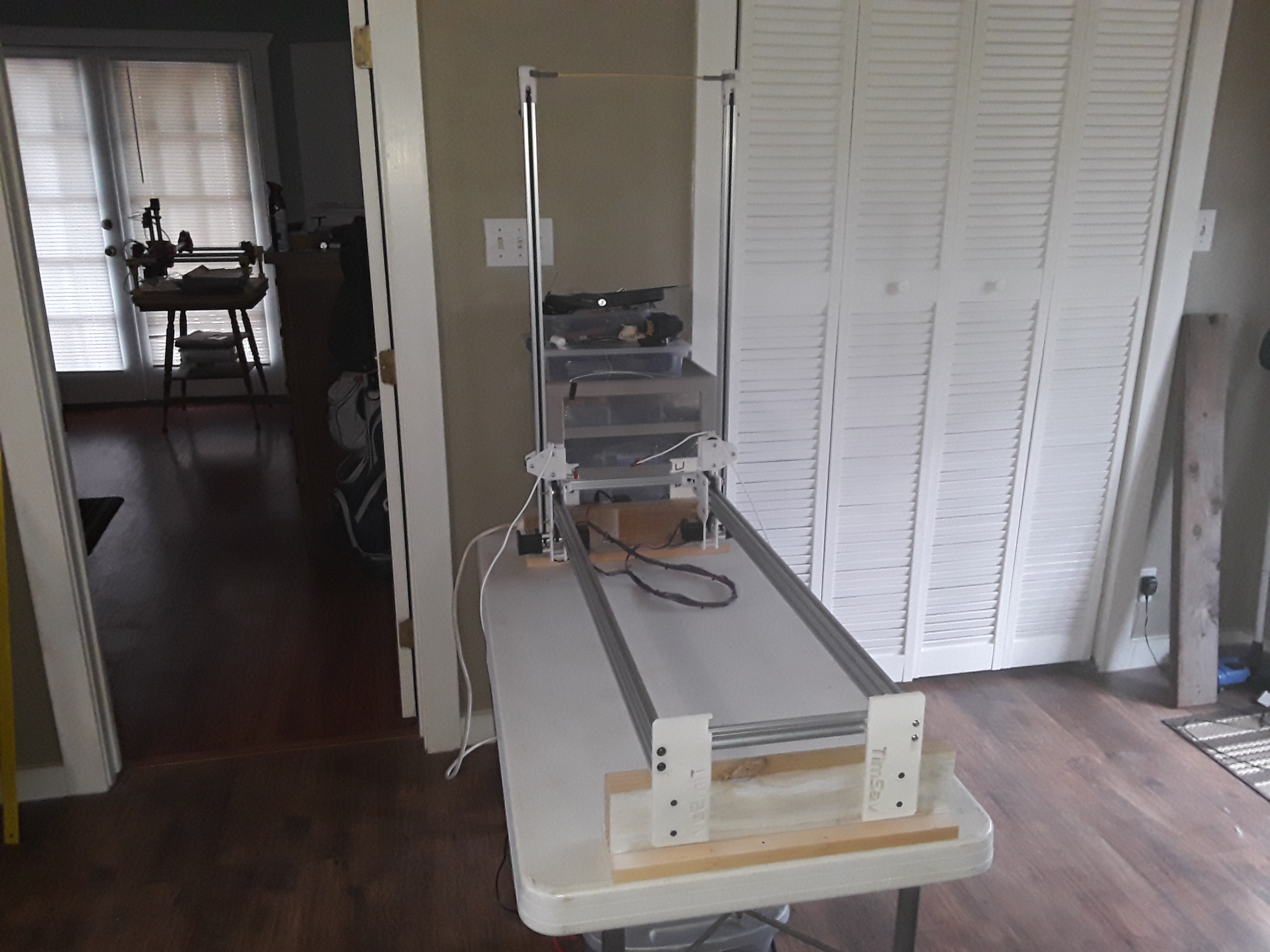
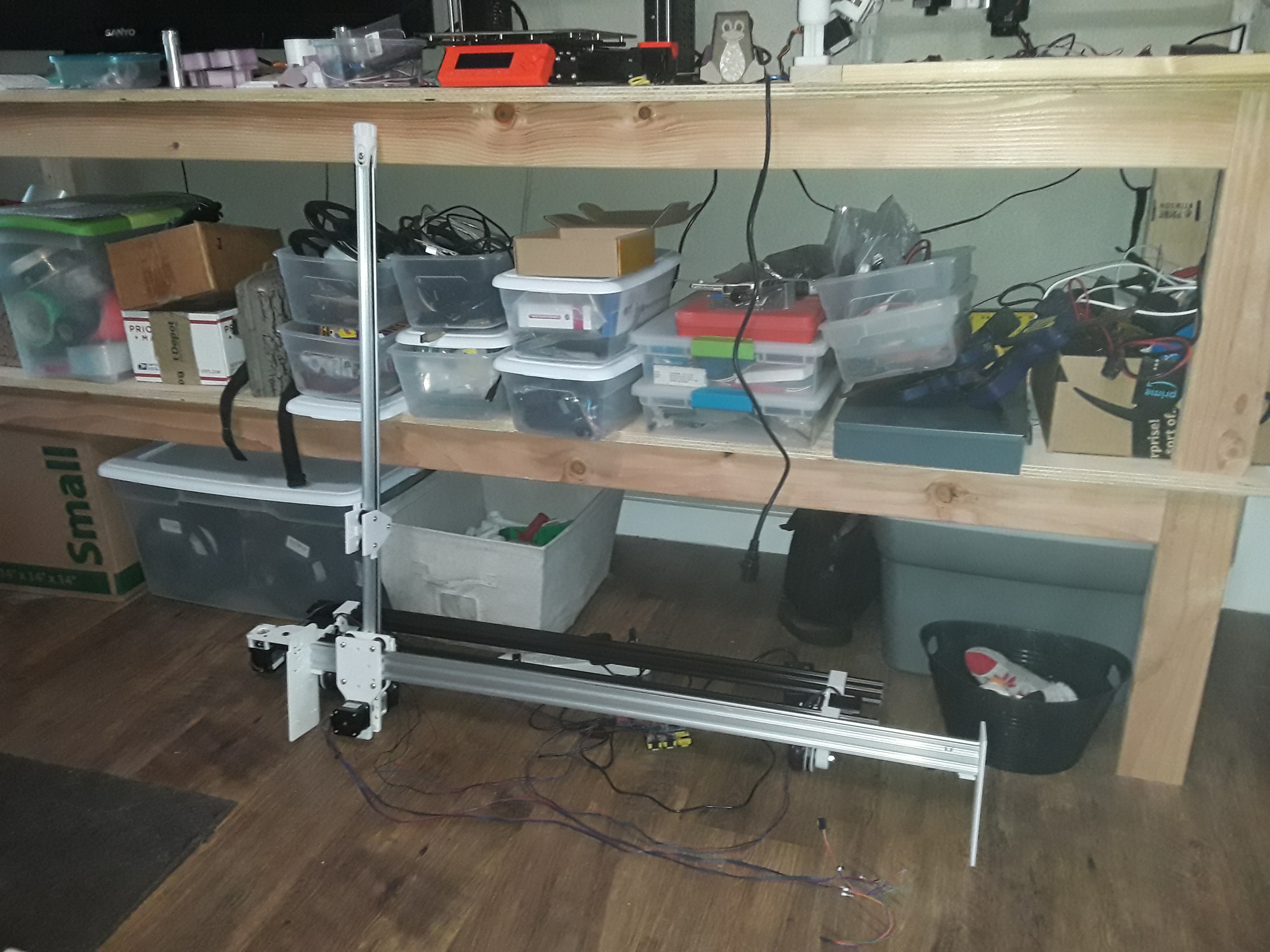
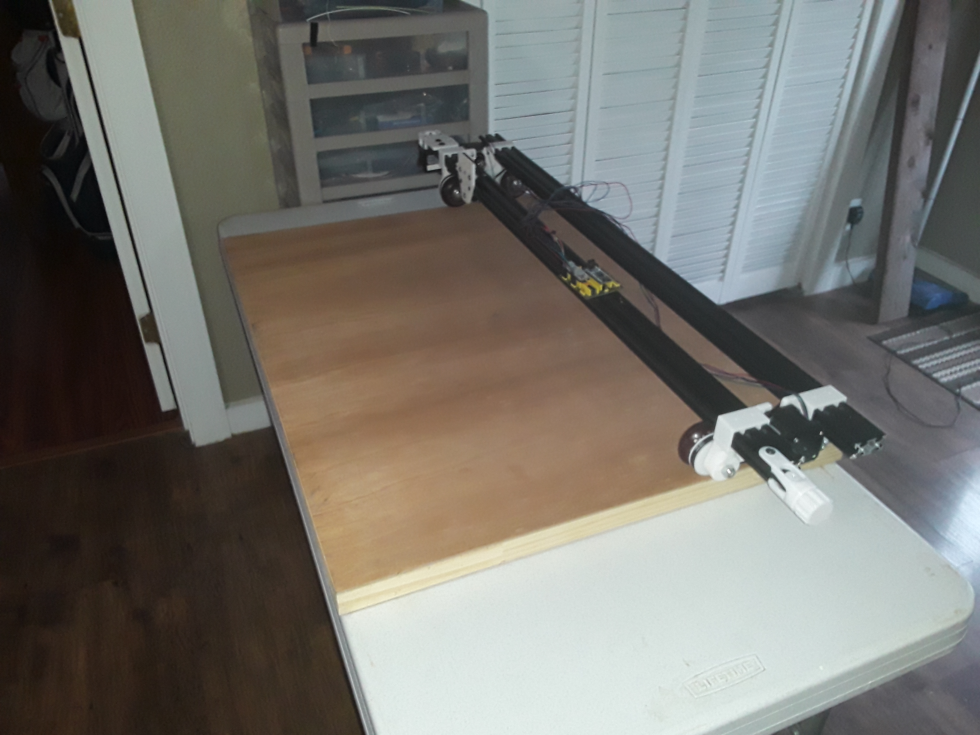
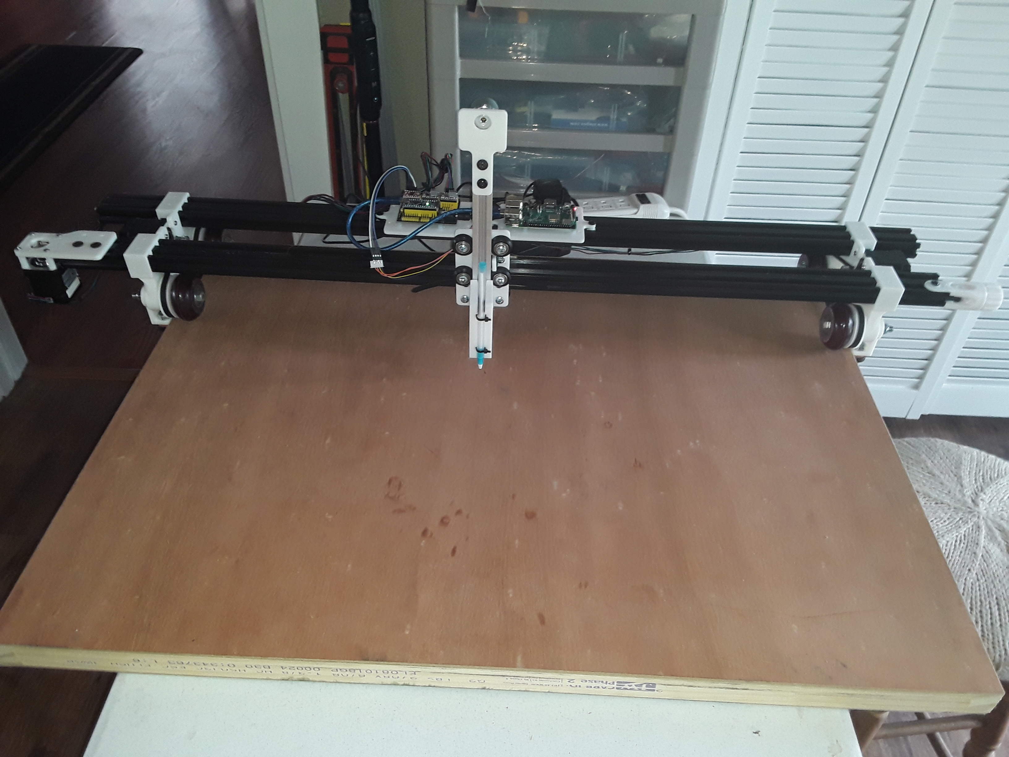
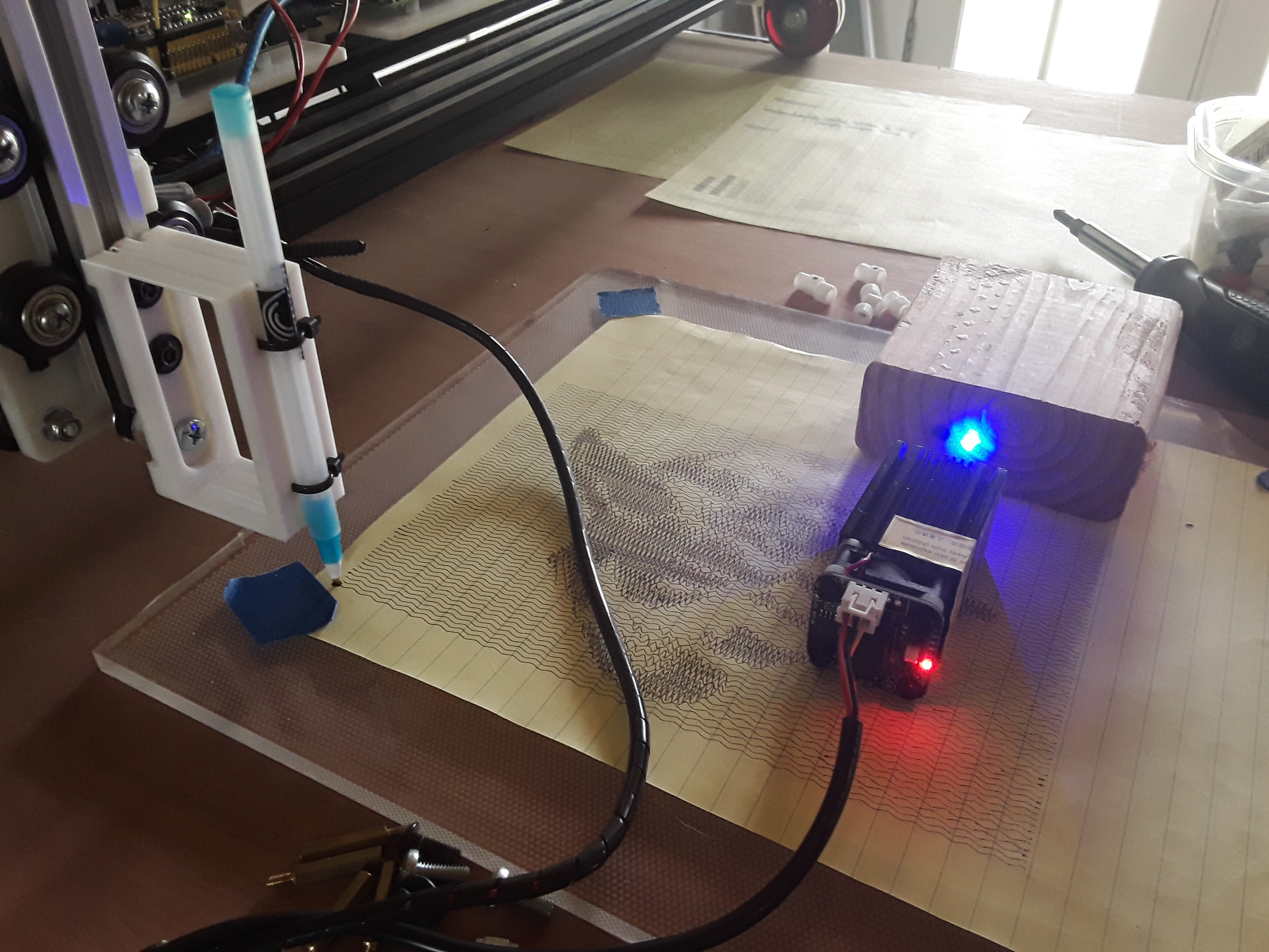
And finally, the entire 3-axis machine, sitting on the cluttered work bench...
View attachment 172842
I'm pretty sure I'll have to have a guide of some sort to keep the wheels tracking in a straight line... I noted a little drift in some earlier "to & fro" tests. Maybe just "fender skirts" or "curb feelers", attached to the axles on both ends, and extending slightly below the work surface... and the tractor-to-tractor spacing adjusted accordingly.
View attachment 172843
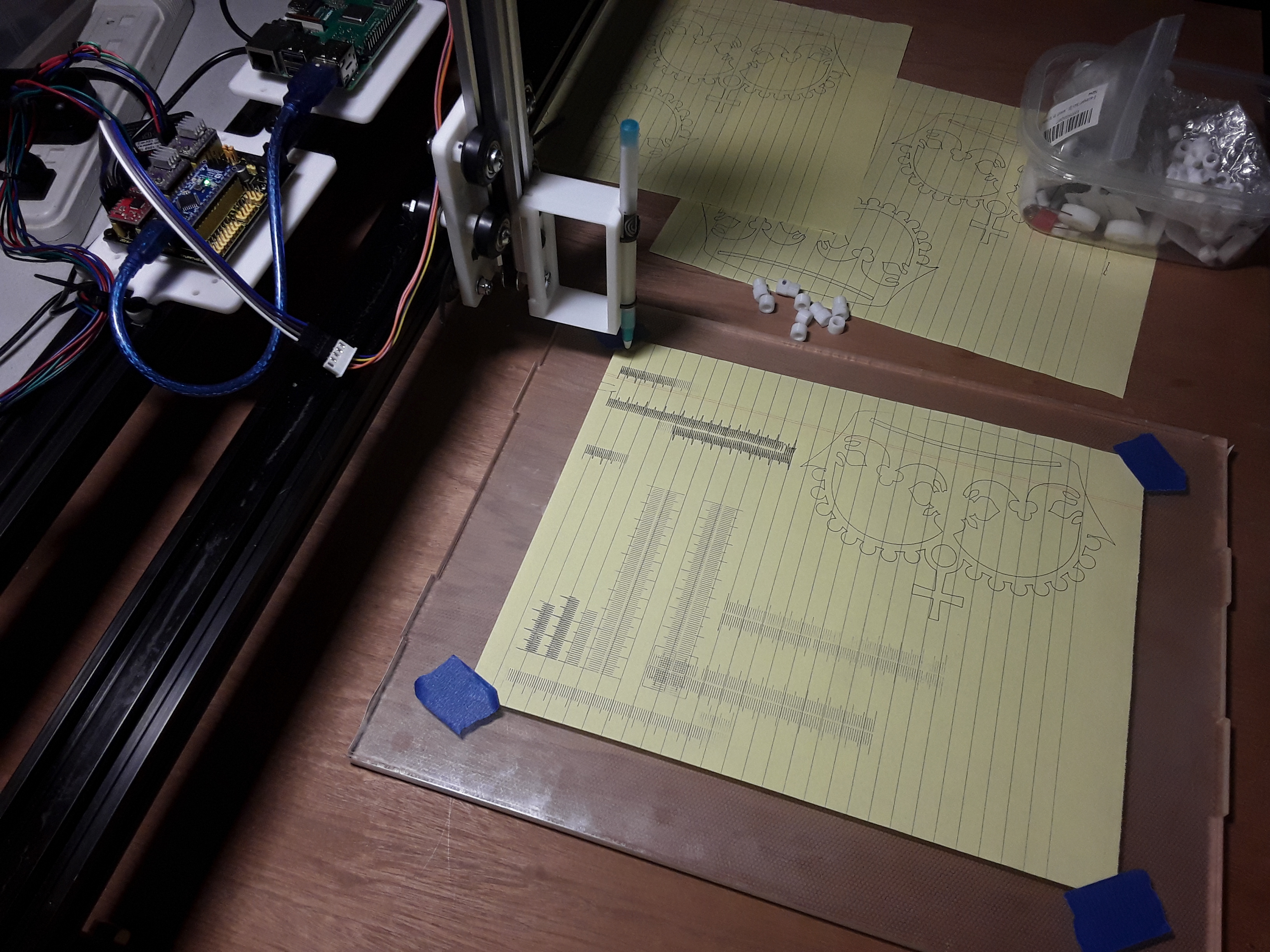
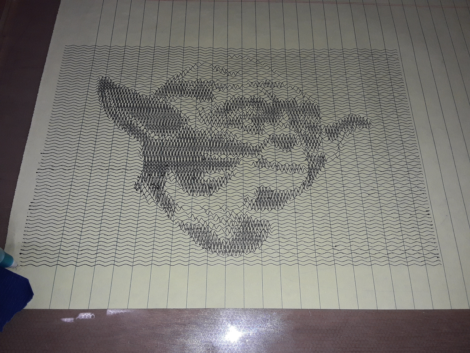
I'll need to adapt a pen-holder to attach to the Z-axis and hopefully start running a few tests. I'll start first with the obligatory MPCNC crown and hopefully then a few of Jamie's rulers. It's been a fun build.
-- David

")