Cutting foam sheets... with a needle!

GremlinRC

FT_Nut
:);):D you don't like black dots?
For mounting the needle guide -> this special nut will do a good job?!

Excellent Idea Joachim... and as mig tips tend to have standard threads it will be easy to find a nut to fit!

Yes I think delrin would work just as well as PTFE. One other benefit of PTFE is it can tolerate high temperatures well.
 
Welcome, Warhawk! I see you found us okay. One thing you will note here... this is a place not only to talk about stuff, but do it... or at least make the attempt. Most of us like to work with our hands, and our tools, to make stuff... and everybody seems to get a real big kick out of trying to "do the impossible, with next-to-nothing, in no time flat" ;)

First, I apologize for the length of the thread... but it will be worth your time to work your way through it; i.e. there's lots of good information throughout. This started as an introduction to cutting foam with a reciprocating needle cutter I developed 6-7 years ago (not my original idea... but adapting to conventional 3-axis CNC was), to cut fanfold insulation foam for RC aircraft. And since it's primary use is with a CNC machine... those are fair game, too. And other tools are potentially of use as well... drag-knives, lasers, dremels, etc... so they are not off-limits either. Everybody seems to be extremely happy with the "spirit" of the thread and its content and the information sharing is tops... and there are some really talented -- and extremely helpful -- folks here.

The KISS philosophy the original cutter is based on has been tested over and over again... and continues to hang around. The last 25 pages or so, we've looked at a number of ways to straighten the path of movement of needle-in-guide and it has resulted in major improvement to the original cutter... with only simple modifications. Cutters with more moving parts have been devised -- and demonstrated -- but largely they suffer when it comes to simplicity, durability and performance.

But it's all fun to play with. And I hope you like to get your hands dirty. Based on the ideas/questions you have, I'd suggest reading through the last 25 pages or so to get an idea of where we've been and what we've looked at... and then join in the discussion. Everybody is friendly and helpful and seems to be having a ball.

Welcome to the party!:D

-- David
Right right

I just finished printing the last printable components for my MPCNC, the toolholder and the spacers (I have a tote full of parts...just waiting till tax return so I can order the hardware and electronics.
I plan on making mine 36x" x 36"Y x 4"Z

I was just offering up proof of concept and or alternate ideas (you guys have probably thought of these well before me) just thought I would help

I found this as well..a solenoid motor...using a hunk of 8mm rod (we already have that with printers and whatnot) build a straight linear drive system

https://www.youtube.com/watch?v=wZiPAJXnT6M
As you can see the guy ran that motor at a fairly substantial speed with moderate voltages and very low current and it appears the throw is at least 7-10mm
Now just take one of his "pistons" and put a push/pull circuit on it, one that is tuneable for frequency and viola...

Once I get my MPCNC moving and running...I will definitely be burning off some FliteTest designs...(my kids really want to get into RC) and with simple cheap planes I can make in a few hours vs a real expensive balsa one that explodes on first crash....well I think I will go with the foam planes :p

I found a bearing that might work instead of trying to modify one
https://www.amazon.com/uxcell-604UU-Groove-Pulley-Bearing/dp/B00KHSPCT4
604uu, same ones they use in bowden extruders
 
Last edited:
Update
I have a micky mouse way around the issues.

1) boot linux use pstoedit to change pdf to dxf
2) boot win7 start sketchup, import dxf, then save
3) boot linux use the command line to start sketchup (wine SketchUp.exe)

Note if you the switch /DisableRubyAPI you will not have SketchUcam extensions
Run Oracle VM VirtualBox on your windows machine...install a working copy of linux on the virtual computer...when you need linux...voila...no need to reboot the machine (you will need more RAM, unless you only give say 1-2 Gigs ram for the virtual machine)
 
Well Jason, this might interest you. My next job this evening was to hook up the prox sensor to an arduino and an LCD screen so I could have a permanent rpm counter attached to my needle cutter and thus actually dial in the rpm that I wanted to cut at. I'll make up a full schematic for anyone interested and the code can be had here;
https://drive.google.com/file/d/0B17H2V7mbN-MZlhTdnRjSW5Jemc/view?usp=sharing

Just hook up the black wire to pin 2, the brown to the 5v rail and the blue wire to ground. Hook up the LCD as normal and away you go.

The code is too simple in that it just counts the ticks using the rising edge of an interrupt and reports the rpm (as freq * 60) every 1 second. because it multiplies whole units by 60, thus 60 is the minimum resolution. I may look at it again, but this is fine for my purposes. I tested it alongside the scope based meter and the two agree (within the 60 resolution).

View attachment 81629

Cheers Dave.

PS anyone having problems with the forum tonight. Seemed to be down for the last half hour or so?
Nice...will this help your tach?
http://www.pyroelectro.com/tutorials/tachometer_rpm_arduino/index.html
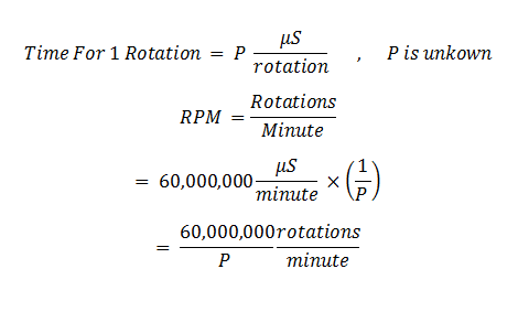
formula.png


This is only partial code
Code:
  //Update The RPM
  if(time > 0)
  {
    //5 Sample Moving Average To Smooth Out The Data
      rpm_array[0] = rpm_array[1];
      rpm_array[1] = rpm_array[2];
      rpm_array[2] = rpm_array[3];
      rpm_array[3] = rpm_array[4];
      rpm_array[4] = 60*(1000000/(time*7));    
    //Last 5 Average RPM Counts Eqauls....
      rpm = (rpm_array[0] + rpm_array[1] + rpm_array[2] + rpm_array[3] + rpm_array[4]) / 5;
  }
 
 }
}

//Capture The IR Break-Beam Interrupt
void fan_interrupt()
{
   time = (micros() - time_last); 
   time_last = micros();
}
Remember that the CPU fan has 7 blades, so this tachometer is only meant to work with fans like that. If your fan or encoder only sends 4 pulses per rotation, you'll want to change that in the code so that "(time*4)".
So with you sensor, it will only get 1 pulse per rotation

Should be able to use a arduino nano for this as well

Cool design and implementation though!
Very very cool!
 
Last edited:

dkj4linux

Elite member
You have quite a variety of good ideas and interesting links, Warhawk. It'll be interesting to sort through them all and come up with some working models. -- David
 
Last edited:

GremlinRC

FT_Nut
Nice...will this help your tach?

Thanks Warhawk for all the cool stuff posted. Yes actual timing will aloow single rev resolution. I will certainly be doing that at some point but for now, I'm happy to report within 60rpm.

My wife would kill me if I started to pull a fridge apart, I'll just blame you:)
 

x33

Member
...My wife would kill me if I started to pull a fridge apart....)

This fridge compressor is a not so nice solution...it stinks! ;)
I tried to use such a modified compressor for sheeting foam wings with balsa in a vacuum bag....worked fine and was not to noisy...but I did not like the constant "odor" of the oil...I used 2 oil traps in a row and a filter...but after half an hour or so the room was smelling like the production plant of a big oil company. :(
In a fridge, the motor is only running ~30% of the time - (in very hot areas may be 50%) but the motor will heat up when running for longer time...so the heated oil is stinking even more.

The special oil is used because of the chemical reaction to the cooling fluid only...I changed it to transmission fluid....
.....the result: after time, the room was smelling like a pit lane in a stockcar event. :)
I made up my mind, that this vapor could not be very healthy too...so I canceld this project.

Could be, I got a special type of compressor???....
May be, the conversion to an Airbrush-compressor works better than using it for making vacuum???....
...I don't know!

Greetings from (still) cold Germany
Joachim
 
Last edited:

Basscor

New member
Progress has been made, here is the current version. I have added another set of bearings to keep it straighter as it enters the guide.

IMG_0227.JPG

IMG_0228.JPG

Here is the needle blur. I setup the block so that the needle is centered in the guide through the full rotation.

IMG_0229.JPG

So far so good, made a couple of 6 minute tests for the wife and they came out alright. The machine movements seem to be a little jerky, but I'm not losing steps. It's probably because the rails aren't broken in yet since it hasn't been used much.
 

GremlinRC

FT_Nut
So far so good

That really looks like a grade A cutter. It's noticeable how straight the needle is between the bearings. My only slight suggestion is to make it a little taller, that will reduce the fatigue on the needle where it bends most entering the bearing guide.

Maybe a light wipe of some machine oil or lithium grease on the rails might help with the jerkiness?

Really great stuff. Keep up the good work!
 

x33

Member
Progress has been made, here is the current version....
....
....made a couple of 6 minute tests

Hi, that looks nice!
Could you feel any heating up of the copper guide after the tests? (I don't think so)

@GremlinRC --> A longer needle will be a good idea for a better MTBF ;)

Joachim
--------------------------------------------
P.S.
just made an oder:
http://cgi.ebay.de/ws/eBayISAPI.dll?ViewItem&item=322412208633
http://cgi.ebay.de/ws/eBayISAPI.dll?ViewItem&item=322412384573
will try to build a router like this
https://youtu.be/AllEIjwd4_I
(smaller version with 65x65cm toolpath)
-----------------------------------------------
BTW - is this a fake? or is this serious??????
---> "The hanging mill" ;) :)
https://www.kickstarter.com/projects/1830738289/maslow-cnc-a-500-open-source-4-by-8-foot-cnc-machi
 

Verris

Active member
Table is coming alone nicely, just need to attach the top. Had to rearrange the office and it's getting a little tight in here but it fits!

IMG_20170212_121933.jpg

Bonus dog.
IMG_20170212_112414.jpg
 

Basscor

New member
@Joachim

No significant heat buildup. After a 10 minute cut is was slightly warmer than room temp. Once the needle wears out I will make a taller cutter. Right now I am using Jason's tall cutter.
 

dkj4linux

Elite member
@Joachim

No significant heat buildup. After a 10 minute cut is was slightly warmer than room temp. Once the needle wears out I will make a taller cutter. Right now I am using Jason's tall cutter.

While your needle should last a while as is (I've made shorter ones that did fairly well for quite a while), Jason's taller cutter was to lessen the severity of needle flex on my original cutter configuration... where the transition to "straight line" motion was at the top of the needle guide. You've effectively moved that point upward, toward the motor, where the upper bearings now force that transition... and once again the angle is made more severe. A taller one, with longer needle, would help in your four-bearing configuration.

Everything is looking great BTW! :D -- David
 

Basscor

New member
Right, with severe being relative. It's working now so I don't feel the need to make the cutter taller again until something breaks and I will then rebuild the whole cutter at once.
 

dkj4linux

Elite member
I'm..mm..mm back!

Took a little time to help fishing/flying/CNC buddy with his needle cutter. It was an early model and sat for a long time... the flywheel was broken for some unknown reason and the whole thing vibrated uncontrollably. So took the opportunity to work on a 3d printed version of my latest cutter (with sideboards) and I'll hopefully get him updated with a more reliable version as well.

I used Jason's parametric needle cutter to give me a basic platform with another 5mm height increase and imported into Tinkercad to add a sideboard mount. I printed a couple of copies so I'll have one to play with and the other for my buddy. I also printed sideboards to check the fits and clearances... until I can come up with some PTFE or somesuch. -- David

20170214_111400.jpg

20170214_111432.jpg

20170214_111411.jpg

20170214_110710.jpg

20170214_110720.jpg

20170214_110851.jpg

20170214_110914.jpg
 
Last edited:

GremlinRC

FT_Nut
That looks pretty cool David. Yes PTFE will definitely finish that off nicely. Just wondering how much infill you use on these printed cutters? I will probably have a go at making my own version too. I may well try Basscor's idea of the 4 bearings to keep the needle totally straight. Took delivery of a big stash of piano wire today so got lots to play with:)