ERC TimSav - Cheap DIY CNC Foamboard Cutter

CapnBry

Elite member
I was pretty close to ordering the Pi zero W without the UART the other day. I was thinking it would be fun to learn how to ssh into it without a GUI. If you don't mind sending it up north to Canada I'd love to take ownership of the little guy!
Especially to our friends in the North! Send me a message with your address and I'll drop it in the mail next time i am out scavenging for groceries.
 

CapnBry

Elite member
I love parametric design. "Sure wish I could fit the carriage on 40mm extrusion to see it in action" and less than five minutes later I had a 40mm version with just the top extended.
DSC06983.JPG


  • New shorter bottom Y plate has a lot less flex in it and most importantly the motor shafts aren't docking with each other any more.
  • Backplate installed on carriage, although probably not needed
  • 3D printed X idler with 608ZZ (?) bearing. I'm out of all 5mm ID bearings so let's make it work with this! Actually a smashing success.
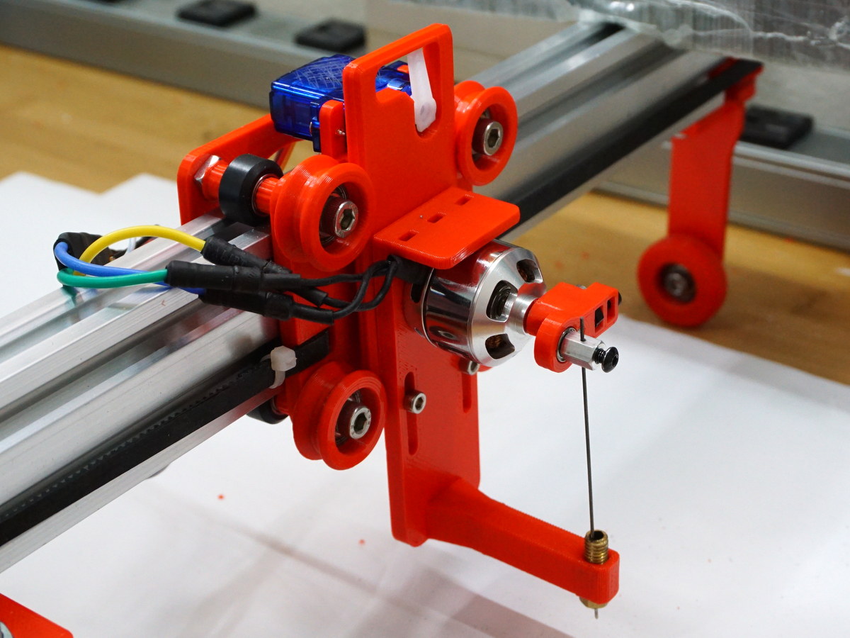
I need to figure out how to stash the wires coming off the carriage. The ESC wires are too short so the only place to put it is strapped right to the motor. I think I am going to extend the motor toolplate down so it can have a space to strap the ESC down, and probably add a bearing close to the drill bit too. I'll also need to add a tab to the carriage to secure all the wires. I want to make new wiring for the carriage run so it only sends 12V, GND, and the two servo signals. 5V can come from the ESC BEC instead of USB power.

Today we'll try to cut something! The motor is loud and somewhat unbalanced. I don't know if these collets were made to run at 10-15K RPM an I am afraid to even turn it up past half throttle.
 

Boberticus

Active member
man i thought i was following this thread, i have like 8-9 pages to read, y'all are running a spindle now!?!?!?!?

fudge man, now i really want one. I'm printing a MPCNC and just have a day or so left of printing the biggest parts, but man am i feeling a bit of "Printers Remorse".

After a CNC i want a laser, I wonder how much slop would be acceptable on this bad boy with a 2.5mw 450nm module slapped on there, a bit of shielding that travels with the head, and a 3d printer style exhaust fan to some CPAP tubing for venting of fumes... i mean sure it'll double the price of the machine, but if it it could cut balsa and plywood and be configured to any dimensions...
 

CapnBry

Elite member
ALERT! The grbl code I posted has a bug where changing the motor speed resets the up/down servo to the 0 position. I'll have a fix by tomorrow but be advised it should not be used unless you set the motor speed first then only use up/down after that. This bug has been fixed and the attachment grbl-1-1h-dualservo.zip above has been updated.

After a CNC i want a laser, I wonder how much slop would be acceptable on this bad boy with a 2.5mw 450nm module slapped on there, a bit of shielding that travels with the head, and a 3d printer style exhaust fan to some CPAP tubing for venting of fumes... i mean sure it'll double the price of the machine, but if it it could cut balsa and plywood and be configured to any dimensions...
I also considered slapping a laser on there, but they get expensive fast. A 500mW laser is incredibly affordable but it won't cut white paper unless you give it all day. 1W is starting to get pricey and bulky and then it just gets worse from there. The best thing about the TimSav is how little it takes to make one. The 3D printing is like half a day total and the fact that I have been replacing virtually every BOM part with what I have on hand and it still works is a testament to how a good simple design is just easier to make.

I just made my first CNC-controlled cut! I gotta work out a way to balance the bit because the vibrations even at 25% throttle the cut is pretty wide due to the bit moving a couple mm as it rotates.

Out of curiosity, what sort of feed rates are folks with needle cutters using? I'm just curious about the ballpark of how fast is fast and how slow is slow.
 
Last edited:

CapnBry

Elite member
DSC06987.JPG


Well, results weren't the worst but they also aren't any good. It is impossible make sure the little drill bit is perfectly coaxial with the motor shaft so it is ever-so-slightly off and wobbles. It is worse at lower throttle but even maxed out it still is visibly shaking. It is also very much affected by how much material it is cutting through. If I just cut the paper it is bad, score cut is teensy worse, full cut you can see the toolhead bending opposite the direction of travel. Slowing down the feedrate seems to make it a bit worse as the drill bit has plenty of time to vibrate in every direction and make the cut wider.

This is with an 0.0465" drill bit (1.1811mm) which is pretty big, but the bit bends even on these so I'm hesitant to shift down to my lower size bits and have them get instantly snapped, although they'd be moving less material so maybe it would be a little better? I also tried a 2-pass cut, one score, one full and it was equally bad.

I'll destroy some more of my precious quarantine DTFB supply tomorrow but I'm not sure I'll be able to find any set of parameters that make it work as well as the needle. There's just a lot more things that can mess up the cut I think with the bit vibration, the bit wanting to push the material and TimSav around, the long arm between the motor mount and the work, and the fact that the bit is made to make a hole not cut sideways.
 

Mortis

Member
My lite kit has been shipped! Still waiting on the v-slots not sure when they'll arrive. What's the best way to cut the 2020, can I cut it with a miter saw? I doubt my ability to cut it straight with a hacksaw.

Is anyone willing to print the 3d printed parts for me? I can pay...
 

CapnBry

Elite member
ok now i need a second one so i can set it up for routing balsa.
Just change your toolhead! Although I will note that this design is not especially suited for milling because it needs to be bolted down to prevent the cutting from just pushing the TimSav around. I guess that's pretty easy to fix with a drill, a piece of MDF, and some 90 degree angle mounts though. The bigger problem is the vibration in the chuck and the super-long length of the drill assembly-- there's a reason dremel tools don't have a 70mm long chuck.

I've fixed the bug in the grbl code I posted that made M4 also set M3 S0 in some cases. I also fixed M5 not shutting down M4 if M3 was already S0, and M4 now happens in sync with the planner instead of immediately. The updated code is in my original post, there are no known issues with it now. Quick usage:
  • In MI GRBL Z-AXIS Servo Controller settings, change your "Servo down" from M5 to M3 S0. Otherwise your motor will stop every time the toolhead is lifted.
  • When combining your score cut and full cut gcode, make the first line "M4 Sxx" to set the motor speed. The range is the same as whatever you set the M3 servo range to, usually 0-90, e.g. M4 S45 for 50% speed. Also add "M4 S0" to the end of the combined gcode file to turn the motor off.
 
Last edited:

dutchmonkey

Well-known member
Just change your toolhead! Although I will note that this design is not especially suited for milling because it needs to be bolted down to prevent the cutting from just pushing the TimSav around. I guess that's pretty easy to fix with a drill, a piece of MDF, and some 90 degree angle mounts though. The bigger problem is the vibration in the chuck and the super-long length of the drill assembly-- there's a reason dremel tools don't have a 70mm long chuck.

My highly modded timesav is bolted down and folds up for storage. So making a dedicated balsa table is no big deal. Plus most sheets are under 6 x 36 so not a big foot print to deal with. I could probably mount this flat on the wall to save space as well.
 
I got notice that my unit is shipping this week. Yay!

I need to start printing parts but you guys can't seem to leave a good thing alone!:) How do I know what are the latest and greatest parts? Are the stl files at Thingverse updated?

There are two places, here and Facebook too that have threads. It is very time consuming to glean all the information from so many pages.

Hey, this thing is supposed to be saving me time!:)
 

CapnBry

Elite member
Hey, this thing is supposed to be saving me time!:)
Oh no, you save time later you see! The thingiverse files I believe are the latest version, everyone is just experimenting with swapping out parts for fun or some personal improvements. Everything I am posting is because corona and I am having fun trying to take a great design and build it with just the parts I have on hand.

I have jumped from the Milling ship and onto the needle ship for the past two days. But I don't have suitable teensy bearings or washers or welding tips so this is made from a 3D printer nozzle and the bearing is from a quad motor so bent it wouldn't turn. This is like the 30th attempt at this flywheel in 30 hours but it works pretty well up to around 12000RPM where it starts to need better balancing. The ESC will zip tie to the top.
DSC06997.JPG


The bearing is 3mm x 8 x 4 and threads into an 8mm aluminum standoff from the junk drawer and the needle is held captive with the M3 screw through the 1mm hole I drilled (waggles hand) straightish. I had a nylon one on there but it was quickly getting cut into by the force of the set screw. Big shout out to @weisssa who demonstrated the standoff mount a month ago. Very easy to just insert the wire to the right depth at the top of the stroke, finger tighten the screw, then clip the excess. The brass washer that was on the quad's motor sits between the standoff and the bearing, and there's nothing on the back but the bolt head but it does not contact the moving bearing area.

The nozzle is from my old 3D printer, it is a 3mm filament 1.0mm E3D volcano nozzle. I would have used an 0.8mm but the only wire I have is right about 0.8mm and it juuuuuust doesn't fit through the smaller nozzle. I'll get some smaller wire at some point and downsize the nozzle. The motor is placed so the needle just clears the edge of the nozzle on the left and right portion of the stroke. SCIENCE: The nozzle opening is 3.2mm and it is 21mm from top to bottom. Using geometry (?) trigonometry (?) triangles (!) that means the motor shaft needs to be 3.2 / 21 = stroke / X. My fattie bearing has a 11.17mm stroke (ugh too giant) so the motor is placed at 73.30mm from the nozzle tip.

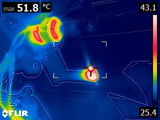
FLIR0191.jpg
FLIR0192.jpg


After 20 minutes of running at 8000RPM, the nozzle is the hottest thing at 52C. This whole TimSav is printed in PLA+ sooooo that will have to be replaced with something a little more heat resistant before that whole arm goes hot and flacid. The bearing mount didn't even really show up compared to the motor, but probably would be better in PETG or ABS for safety.

I wish the Arduino had a second serial port on it because it would be sweet to use a blheli_32 ESC and get RPM telemetry from the motor. I had one hooked up for testing and at 12V I get 8000RPM at 31% throttle on my 1130KV motor, pulling about 300mA, but I'm not sure I'd trust the current reading from the ESC since the power is so low compared to its 35A rating. I might grab a cheap 900ishKV motor to replace this one to get more control, however the GRBL servo control literally only has 16 power levels / servo steps anyway.
 

KalleFly

New member
Oh no, you save time later you see! The thingiverse files I believe are the latest version, everyone is just experimenting with swapping out parts for fun or some personal improvements. Everything I am posting is because corona and I am having fun trying to take a great design and build it with just the parts I have on hand.

I have jumped from the Milling ship and onto the needle ship for the past two days. But I don't have suitable teensy bearings or washers or welding tips so this is made from a 3D printer nozzle and the bearing is from a quad motor so bent it wouldn't turn. This is like the 30th attempt at this flywheel in 30 hours but it works pretty well up to around 12000RPM where it starts to need better balancing. The ESC will zip tie to the top.
View attachment 165715

The bearing is 3mm x 8 x 4 and threads into an 8mm aluminum standoff from the junk drawer and the needle is held captive with the M3 screw through the 1mm hole I drilled (waggles hand) straightish. I had a nylon one on there but it was quickly getting cut into by the force of the set screw. Big shout out to @weisssa who demonstrated the standoff mount a month ago. Very easy to just insert the wire to the right depth at the top of the stroke, finger tighten the screw, then clip the excess. The brass washer that was on the quad's motor sits between the standoff and the bearing, and there's nothing on the back but the bolt head but it does not contact the moving bearing area.

The nozzle is from my old 3D printer, it is a 3mm filament 1.0mm E3D volcano nozzle. I would have used an 0.8mm but the only wire I have is right about 0.8mm and it juuuuuust doesn't fit through the smaller nozzle. I'll get some smaller wire at some point and downsize the nozzle. The motor is placed so the needle just clears the edge of the nozzle on the left and right portion of the stroke. SCIENCE: The nozzle opening is 3.2mm and it is 21mm from top to bottom. Using geometry (?) trigonometry (?) triangles (!) that means the motor shaft needs to be 3.2 / 21 = stroke / X. My fattie bearing has a 11.17mm stroke (ugh too giant) so the motor is placed at 73.30mm from the nozzle tip.

View attachment 165724 View attachment 165725

After 20 minutes of running at 8000RPM, the nozzle is the hottest thing at 52C. This whole TimSav is printed in PLA+ sooooo that will have to be replaced with something a little more heat resistant before that whole arm goes hot and flacid. The bearing mount didn't even really show up compared to the motor, but probably would be better in PETG or ABS for safety.

I wish the Arduino had a second serial port on it because it would be sweet to use a blheli_32 ESC and get RPM telemetry from the motor. I had one hooked up for testing and at 12V I get 8000RPM at 31% throttle on my 1130KV motor, pulling about 300mA, but I'm not sure I'd trust the current reading from the ESC since the power is so low compared to its 35A rating. I might grab a cheap 900ishKV motor to replace this one to get more control, however the GRBL servo control literally only has 16 power levels / servo steps anyway.
Hi...your needle holder looks great...are you intending to provide stl files for your assembly ? i would love to try it.
thx in advance
 

CapnBry

Elite member
Hi...your needle holder looks great...are you intending to provide stl files for your assembly ? i would love to try it.
Ab. So. Lutely. Sharing designs is what got me to here too so I'll definitely share all of bits I've created. This is the first cutting version in 30 tries though and I still haven't located the bearing assembly that flew off last night so I'm just going to get some cuts under my belt before I think it isn't dangerously flawed. I was wearing eye protection when the bit flew off though, it may only be 5g but it has a sharp needle going at 10krpm, of course I am going to wear eye protection testing it! :)

In just a few short tests I am wondering if it needs more mass though. I've seen that bit called the "flywheel" and I wondered why a needle poking through paper would need more momentum than the motor would impart, but I see some places where the needle didn't go all the way through the bottom paper on some cuts so I'm wondering if making the needle attachment lighter is a bad thing instead of a vibration thing. I still have a lot of trial to do to know for sure, but my needle is 0.8mm instead of 0.6mm so maybe it would be better if I got some more suitable material.
 

dkj4linux

Elite member
..I was wearing eye protection when the bit flew off though, it may only be 5g but it has a sharp needle going at 10krpm, of course I am going to wear eye protection testing it! :)

In just a few short tests I am wondering if it needs more mass though. I've seen that bit called the "flywheel" and I wondered why a needle poking through paper would need more momentum than the motor would impart, but I see some places where the needle didn't go all the way through the bottom paper on some cuts so I'm wondering if making the needle attachment lighter is a bad thing instead of a vibration thing. I still have a lot of trial to do to know for sure, but my needle is 0.8mm instead of 0.6mm so maybe it would be better if I got some more suitable material.
You've got a really good looking cutter going there... but please take care while testing this thing. Best is to go slow at first... and build up to speed as you get a feel for how it's going. I recommend getting a tach and staying in the 6000 - 8000 rpm range for initial testing... and I usually use a "rule of 10" for appropriate feed and speed; i.e. cutter speed (rpm) 10X the feed rate (mm/min) gives 10 perforations per millimeter of linear travel. This should result in clean cuts in paper-clad foamboard, such as the Adams foamboard sold in many "dollar stores". Some of my early cutters used brushed motors, scavenged from inkjet printers, and only ran at about 4000 rpm... and my late fishing/flying buddy and I used them to cut bunches of fanfold foam airplanes, which we built and flew in my pasture.

That "flywheel"/eccentric bit really just serves to set the stroke length and provide a solid (hopefully) attachment point for the needle. You're really doing well if the "flywheel" bit simply does its job and doesn't cause too much imbalance. The motor itself provides all the impetus needed to power the needle through the foamboard... while torture testing some of my early cutters I was cutting cardboard and even coroplast. I've never measured it but there is a gigantic amount of force concentrated on the point of a properly sharpened needle... keep your fingers out of the way.

And not all cuts are through-cuts, of course. Scoring- and marking-cuts should also be possible... maybe a bit more touchy with a servo-driven Z than with a fully-implemented Z-axis but still possible if properly adjusted. Key to making good cuts, of all types, is keeping the foamboard workpiece as flat as possible. A vacuum pad made with 3 sheets of DTFB can be readily fashioned to hold the workpiece flat and firmly enough to get good cuts. But many sheets of foamboard have been cut without one... simply putting the "crown" down (like a dinner plate) and then pinning/weighting/clamping the edges of the foamboard is usually enough to get reasonable cuts. The 3 sheets of the vacuum pad makes a wonderful first project for your new needle cutter... please turn down the sound and I apologize for the autofocus issues


I use 0.025" (0.6mm) piano-wire for my needles... and usually buy the straight lengths packaged up and sold online and in hobby stores. I shy away from the coiled wire so many are trying to straighten and use with the TimSav machines. It should also have a proper point... like a sharp wooden pencil. I usually just lightly touch the tip of the needle against the side of my grinding wheel, at an angle, and "twirl" the needle with my fingers. A properly sharpened needle will cut equally well in all directions... without any discernable "favoring" one direction over another. It should also leave little/no debris in its wake, as it simply displaces the material (like a rapier) rather than blowing it out (like a bullet); i.e. think "exit wounds" :eek:

All things considered, a needle cutter is a pretty simple device, mechanically, but can be a bit fiddly to get set up and running well. And, generally, it does it does its job with very little power -- only 1-2 amps at 12 volts or so... much less than the same motor swinging a prop to power an airplane through the sky. Given a reasonably well-constructed cutter, it is then the "feeds and speeds" that win out as the most important consideration, followed closely by making sure the workpiece is flat and securely held. And, above all, be PATIENT. It's simply not worth "pushing things" IMHO just to save a couple of minutes over the course of a 20-30 minute cut. I would target 8000-8500 rpm and try to find a "sweet spot", where nothing is stressed, and the cuts are accurate, clean, and stess-free.

Good luck. -- David
 
Last edited:

CapnBry

Elite member
Good luck. -- David
Thanks for all the great detail, David, you've always been someone I follow here for your great technical expertise and excellent taste in operating systems. You always seem to be on the cutting edge :)p) of putting software and hardware together for our purposes, and this CNCjs on my desktop inspired by your photo last week is just one memento from that.

You've given me a lot to consider in your post. You're right about the patience though, I've been 3D printing for coming up on 8 years now and know very well the product of pushing for fast over quality and accuracy. I'm pleased to hear that the weight of the flywheel is not an going to be an issue, as I spent last night working out a way to add 1g to it, and comparing that to the weight of the 3d printed flywheels (4-5g total) and the motor bell at ~25g. I have definitely considered some sort of vacuum to de-crown the foam board, and I am also trying to figure out where I'm going to put this thing to use it, since my workbenches aren't big enough. hahah Now the real fun begins: Thing built, now what?